 Toyota Camry XV30 (2002–2006) Service ManualClutch
Clutch unit
Clutch unit
OVERHAUL
-
REMOVE MANUAL TRANSAXLE ASSY
-
REMOVE CLUTCH RELEASE FORK BOOT
-
REMOVE CLUTCH RELEASE BEARING ASSY
-
REMOVE CLUTCH RELEASE FORK SUB−ASSY
-
REMOVE RELEASE BEARING HUB CLIP
-
REMOVE RELEASE FORK SUPPORT
a. Remove the release fork support from the manual transaxle assy.
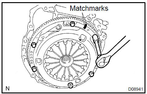
7. REMOVE CLUTCH COVER ASSY
-
Place the matchmarks on the clutch cover assy with the one on the flywheel sub−assy.
-
Loosen each set bolt one turn at a time until spring tension is released.
-
Remove the set bolts and pull off the clutch cover assy.
NOTICE: Do not drop the clutch disc assy.
 Remove clutch cover assy
8. REMOVE CLUTCH DISC ASSY
NOTICE: Keep the lining part of the clutch disc assy, the pressure plate and surface of the flywheel sub−assy away from oil and foreign attachment.
9. INSPECT CLUTCH DISC ASSY
a. Using vernier calipers, measure the rivet head depth.
Maximum rivet depth: 0.3 mm (0.012 in.)
If necessary, replace the clutch disc assy.
b. Install the clutch disc assy to the transaxle assy.
NOTICE: Take care not to insert the clutch disc assy in the wrong direction
c. Using a dial indicator, check the clutch disc assy runout.
Minimum runout: 0.8 mm (0.031 in.)
If necessary, replace the clutch disc assy.
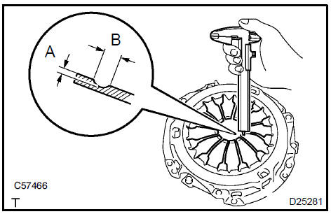
10. INSPECT CLUTCH COVER ASSY
a. Using vernier calipers, inspect the diaphragm spring for depth and width of wear.
Maximum:
A (Depth): 0.5 mm (0.020 in.)
B (Width): 6.0 mm (0.236 in.)
If necessary, replace clutch cover assy.
Inspect clutch cover assy
11. INSPECT FLYWHEEL SUB−ASSY
a. Using a dial indicator, inspect the flywheel sub−assy runout.
Maximum runout: 0.1 mm (0.004 in.)
If necessary, replace the flywheel sub−assy.
 Inspect flywheel sub-assy
12. INSPECT CLUTCH RELEASE BEARING ASSY
a. Turn the release bearing assy by hand while applying force in the axial direction.
HINT: The bearing is permanently lubricated and required no cleaning or lubrication.
If necessary, replace the release bearing assy.
 Inspect clutch release bearing assy
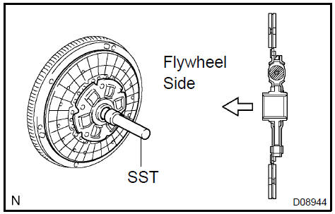
13. INSTALL CLUTCH DISC ASSY
a. Insert SST in the clutch disc assy, then insert them in the flywheel sub−assy.
SST 09301−00220
NOTICE: Take care not to insert clutch disc assy in the wrong direction
.
 Install clutch disc assy
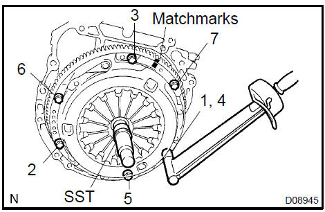
14. INSTALL CLUTCH COVER ASSY
-
Align the matchmarks on the clutch cover assy and flywheel sub−assy.
-
Following the procedures shown in the illustration, tighten the 6 bolts, in the order starting the bolt locating near the knock pin on the top.
Torque: 19 N·m (195 kgf·cm, 14 ft·lbf)
HINT:
-
Following the order in the illustration, tighten the bolts at a time evenly.
-
Move SST up and down, right and left lightly, after checking that the disc is in the center, tighten the bolts.
Install clutch cover assy
15. INSPECT AND ADJUST CLUTCH COVER ASSY
a. Using a dial indicator with roller instrument, check the diaphragm spring tip alignment.
Maximum non−alignment: 0.5 mm (0.020 in.)
If alignment is not as specified, using SST, adjust the diaphragm spring tip alignment.
SST 09333−00013
Inspect and adjust clutch cover assy
16. INSTALL RELEASE FORK SUPPORT
a. Install the release fork support to the manual transaxle assy.
Torque: 47 N·m (480 kgf·cm, 35 ft·lbf)
17. INSTALL RELEASE BEARING HUB CLIP
a. Install the release bearing hub clip to the release bearing assy.
18. INSTALL CLUTCH RELEASE FORK SUB−ASSY
-
Apply release hub grease to the release fork and release bearing assy contact, release fork and push rod contact and release fork pivot points.
Sealant:
Part No. 08887−01806, RELEASE HUB GREASE or equivalent -
Install the release fork to the release bearing assy.
19. INSTALL CLUTCH RELEASE BEARING ASSY
-
Apply the clutch spline grease to the input shaft spline.
Sealant:
Part No. 08887−01706, CLUTCH SPLINE GREASE or equivalent -
Install the release fork with release bearing assy to the manual transaxle assy.
NOTICE: After the installation, move the folk forward and backward to check that the release bearing slides smoothly.
-
INSTALL CLUTCH RELEASE FORK BOOT
-
INSTALL MANUAL TRANSAXLE ASSY
Clutch system (From July, 2003)
Clutch release cylinder assy
Clutch accumulator assy
Clutch unit
Clutch start switch assy
Clutch pedal sub-assy
Clutch start switch assy
Clutch pedal sub-assy
Clutch master cylinder assy
Toyota Camry XV30 (2002–2006) Service Manual
- Introduction
- Audio & visual system
- Automatic transmission / trans
- Brake
- Clutch
- Communication system
- Cooling
- Cruise control
- Drive shaft / propeller shaft
- Emission control
- Engine control system
- Engine hood/door
- Engine mechanical
- Exhaust
- Exterior/interior trim
- Front suspension
- Fuel
- Heater & air conditioner
- Ignition
- Instrument panel/meter
- Intake
- Lighting
- Lubrication
- Manual transmission/transaxle
- Parking brake
- Power steering
- Rear suspension
- Seat
- Service specifications
- Sliding roof/convertible
- Starting & charging
- Steering column
- Supplemental restraint system
- Theft deterrent & door lock
- Tire & wheel
- Windshield/windowglass/mirror
- Wiper & washer
- Wiring
Categories
