 Toyota Camry XV30 (2002–2006) Service ManualInstrument panel/meter
Combination meter assy
Combination meter assy
OVERHAUL
HINT:
- COMPONENTS:
- Installation is in the reverse order of removal.
- REMOVE INSTRUMENT CLUSTER FINISH PANEL
- REMOVE COMBINATION METER ASSY
- Remove the 2 screws and disengage the 2 clips.
- Disconnect the connectors and remove the combination meter assy.
 Remove combination meter assy
3. REMOVE COMBINATION METER GLASS
- Reverse the combination meter and remove the 2 screws.
- Remove the tape.
- Disengage the 7 claws and remove the combination meter glass.
 Remove combination meter glass
ON−VEHICLE INSPECTION
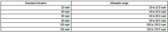
1. INSPECT SPEEDOMETER
a. Check the operation.
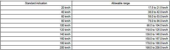
1. Using a speedometer tester, inspect the speedometer for allowable indication error and check the operation of the odometer.
USA (mph):
CANADA (km/h):
NOTICE: Tire wear and tire over or under inflation will cause the indication error.
2. Check the deflection range of the speedometer indicator.
Reference: Below 0.5 km/h (0.3 mph)
2. INSPECT OUTPUT SIGNAL OF VEHICLE SPEED
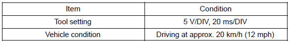
a. Check the input signal wave form.
- Remove the combination meter with connectors still connected.
- Connect the oscilloscope to terminal C7−36 and body ground.
- Start the engine.
- Check the signal wave form. OK: Signal wave form generates.
HINT: A wave form as shown on the left appears if the voltage is 12 V under the following conditions:
HINT: As vehicle speed increases, the cycle of the signal wave form narrows.
3. INSPECT TACHOMETER
a. Check the operation
1. Connect a tune−up test tachometer, and start the engine.
NOTICE:
- Reversing the connection of the tachometer will damage the transistors and diodes inside.
- When removing or installing the tachometer, be careful not to drop or subject it to heavy shocks.
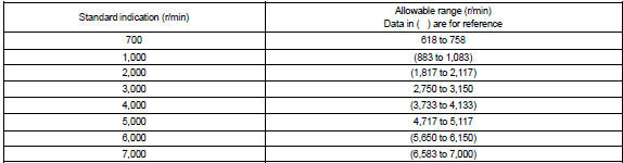
2. Compare the result of the test and tachometer indications.
DC 13.5 V, 25 C at (77 F)
2AZ−FE:
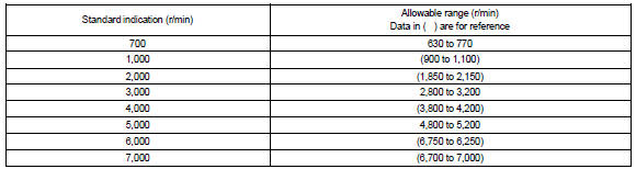
1MZ−FE, 3MZ−FE:
4. INSPECT FUEL RECEIVER GAUGE
a. Inspect the circuit.
- Disconnect the connector from the sender gauge.
- Turn the ignition switch ON, then check the position of the receiver gauge needle.
Standard: Needle position is EMPTY and FUEL warning light comes on.
 Inspect fuel receiver gauge
5. INSPECT FUEL LEVEL WARNING
a. Inspect the circuit.
- Disconnect the connector from the sender gauge.
- Turn the ignition switch to ON, and check the position of the fuel level needle and the FUEL level warning light.
Standard: Needle position is EMPTY and FUEL warning light comes on.
6. INSPECT ENGINE COOLANT TEMPERATURE RECEIVER GAUGE WARNING LIGHT
a. Inspect the circuit.
- Disconnect the connector from the sender gauge.
- Turn the ignition switch to ON, and check the position of the water
temperature receiver gauge
needle.
OK: Needle position: COOL
- Ground terminal 2 on the wire harness side, then check the position of
the water temperature
receiver gauge needle.
OK: Needle position: HOT
7. INSPECT SEAT BELT WARNING LIGHT (Driver Side)
a. Check the operation.
- Turn the ignition switch to ON and check that the warning light lights up.
- Fasten the outer belt to the inner belt and check that the warning light goes off.
- Disconnect the connector from the buckle switch and ground terminal on the wire harness side connector.
- Turn the ignition switch to ON and check the warning light.
OK: Seat belt warning light: Come on
8. INSPECT LOW OIL PRESSURE WARNING LIGHT
a. Inspect the circuit.
- Disconnect the connector from the low oil pressure switch.
- Turn the ignition switch to ON.
- Connect the terminal of wire harness side connector to ground, then
check the warning low oil
pressure warning light.
OK: Low oil pressure warning light: Come on
9. INSPECT BRAKE WARNING LIGHT
a. Inspect the parking brake warning light.
- Disconnect the connector from the parking brake switch and ground terminal on the wire harness side connector.
- Turn the ignition switch to ON and check the warning light.
OK: Brake warning light: Come on
b. Inspect the brake fluid level warning light.
- Disconnect the connector from the brake fluid level warning switch and connect terminals on the wire harness side connector.
- Turn the ignition switch to ON and check the warning light.
OK : Brake fluid level warning light: Come on
10. INSPECT BRAKE FLUID LEVEL WARNING SWITCH
a. Inspect the continuity.
- Remove the reservoir tank cap and strainer.
- Disconnect the connector.
- Check that the continuity exists between the terminals.
OK: Float up (switch off): No continuity
- Use a syphon, etc., to take fluid out of the reservoir tank.
- Check that the continuity exists between the terminals.
OK: Float down (switch on): Continuity
- Pour the fluid back in the reservoir tank.
11. INSPECT SEAT BELT WARNING BUZZER
a. When only driver’s seat is occupied.
- Turn the ignition switch to ON and check that the driver’s seat belt warning sounds if the driver’s seat belt is not fastened about 1.8 seconds after the ignition switch is turned to ON.
- Check that the buzzer stops after about 6 seconds.
b. When both driver’s seat and passenger’s seat are occupied
- When either of the seat belts for the driver seat and front passenger seat is not fastened within 13.8 seconds after the ignition switch is turned to ON, the buzzer sounds for 9.6 seconds.
- When the seat belt is still not fastened after that, the buzzer is switched to level 2 and sounds for 20 seconds.
12. INSPECT KEY REMINDER WARNING BUZZER
a. Check warning buzzer function.
1. Turn the ignition switch off and check that the key reminder warning sounds if the ignition key is inserted into the key cylinder and the front driver side door is opened.
OK : Warning buzzer sounds
13. INSPECT WASHER LEVEL WARNING SWITCH
- Disconnect the connector from the washer level warning switch.
- Turn the ignition switch to ON.
- Ground terminal of the wire harness side connector, then check the
washer level warning light.
OK: Washer level warning light comes o
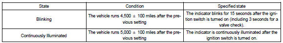
14. MAINTENANCE LIQUID RESETTING PROCEDURE
Indicator Condition:
- Set the display window to ODO.
- Turn the ignition switch off.
- While pressing the reset switch, turn the ignition switch to the ON position (keep pressing for at least 5 seconds).
- Reset procedure is completed.
HINT:
- If the ignition switch is turned off during the reset procedure, reset mode is canceled.
- If the reset switch is turned off during the reset procedure, reset mode is canceled and the display shows the condition prior to the reset procedure.
Combination meter
Instrument panel safety pad sub-assy
Combination meter assy
Clock assy
Combination meter
Instrument panel/meter
Toyota Camry XV30 (2002–2006) Service Manual
- Introduction
- Audio & visual system
- Automatic transmission / trans
- Brake
- Clutch
- Communication system
- Cooling
- Cruise control
- Drive shaft / propeller shaft
- Emission control
- Engine control system
- Engine hood/door
- Engine mechanical
- Exhaust
- Exterior/interior trim
- Front suspension
- Fuel
- Heater & air conditioner
- Ignition
- Instrument panel/meter
- Intake
- Lighting
- Lubrication
- Manual transmission/transaxle
- Parking brake
- Power steering
- Rear suspension
- Seat
- Service specifications
- Sliding roof/convertible
- Starting & charging
- Steering column
- Supplemental restraint system
- Theft deterrent & door lock
- Tire & wheel
- Windshield/windowglass/mirror
- Wiper & washer
- Wiring
Categories
