 Toyota Camry XV30 (2002–2006) Service ManualFront suspension
Front wheel alignment
Front wheel alignment
ADJUSTMENT
- INSPECT TIRE
- MEASURE VEHICLE HEIGHT
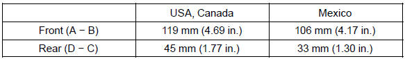
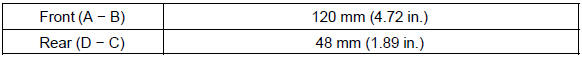
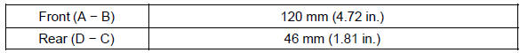
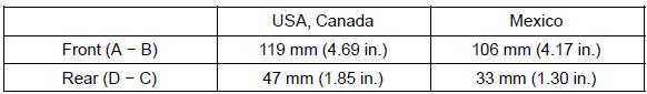
Vehicle height:
2AZ−FE COMFORT:
2AZ−FE PREMIUM:

2AZ−FE SPORT:
1MZ−FE COMFORT:
1MZ−FE PREMIUM:
3MZ−FE SPORT:

Measuring points:
- Ground clearance of front wheel center
- Ground clearance of lower suspension arm No. 2 set bolt center
- Ground clearance of strut rod set bolt center
- Ground clearance of rear wheel center
NOTICE: Before inspecting the wheel alignment, adjust the vehicle height to the specified value.
HINT: Bounce the vehicle at the corners up and down to stabilize the suspension and inspect the vehicle height.
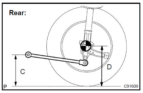
3. INSPECT TOE−IN
Toe−in:

HINT:
- Measure ”A + B” when ”C − D” can not be measured.
- If toe−in is not within the specified range, adjust it at the rack ends.
4. ADJUST TOE−IN
- Remove the rack boot set clips.
- Loosen the tie rod end lock nuts.
- Turn the right and left rack ends by an equal amount to adjust the toe−in.
HINT: Try to adjust the toe−in to the center of the specified range.
- Make sure that the lengths of the right and left rack ends are the same.
- Torque the tie rod end lock nuts.
Torque: 74 N·m (755 kgf·cm, 55 ft·lbf)
- Place the boots on the seats and install the clips.
HINT: Make sure that the boots are not twisted.
g. Perform VSC system calibration.

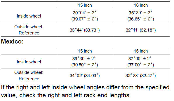
5. INSPECT WHEEL ANGLE
a. Turn the steering wheel fully left and right, and measure the turning angle.
Wheel turning angle: USA, Canada:
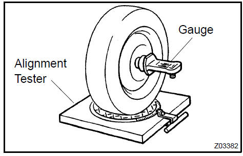
6. INSPECT CAMBER, CASTER AND STEERING AXIS INCLINATION
- Put the front wheel on the center of the alignment tester.
- Set the camber−caster−kingpin gauge at the center of the axle hub or drive shaft.
Camber and steering axis inclination:
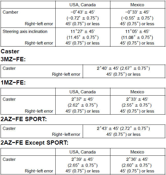
If the caster and steering axis inclination are not within the specified ranges, after the camber has been correctly adjusted, recheck the suspension parts for damaged and/or worn out parts.
7. ADJUST CAMBER
NOTICE: After the camber has been adjusted, inspect the toe−in.
- Remove the front wheel.
- Remove the 2 nuts on the lower side of the shock absorber assy front LH.
- Clean the installation surfaces of the shock absorber assy front LH
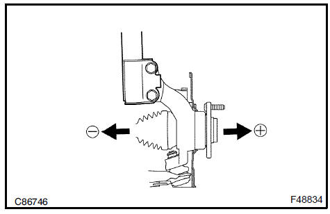
- Fully push or pull the front axle hub in the direction of the required adjustment.
- Tighten the nuts.
Torque: 210 N·m (2,141 kgf·cm, 155 ft·lbf)
- Install the front wheel.
Torque: 103 N·m (1,050 kgf·cm, 76 ft·lbf)
h. Check the camber.
If the measured value is not within the specified range, calculate the required adjustment amount using the formula below.
(Camber adjustment amount) = Center of the specified range − Measured value
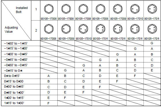
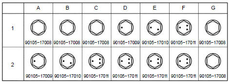
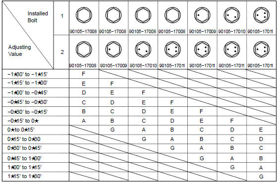
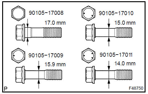
i. Check installed bolts combination. Select appropriate bolts from the table below to adjust the camber within the specified range.
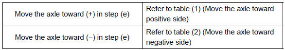
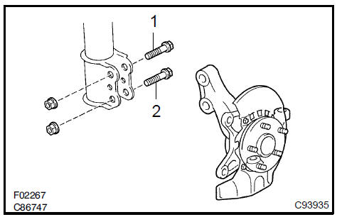
Table 1. (Move the axle toward positive side)
 Move the axle toward positive side
Selected Bolt Combination
The body and suspension may be damaged if the camber is not correctly adjusted according to the above table.
NOTICE: Replace the nut with a new one when replacing the bolt.
j. Repeat the steps mentioned above. At step b., replace 1 or 2 selected bolts.
HINT: Replace one bolt at a time when replacing 2 bolts.
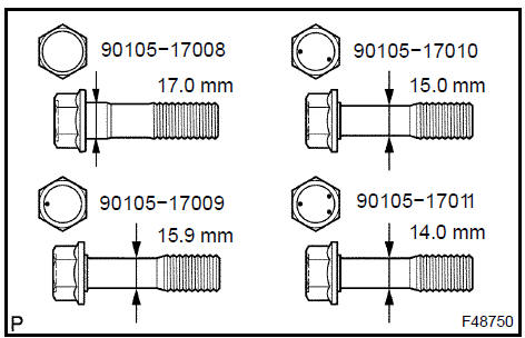
Table 2. (Move the axle toward negative side)
 Move the axle toward negative side
Selected Bolt Combination
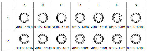
The body and suspension may be damaged if the camber is not correctly adjusted according to the above table.
NOTICE: Replace the nut with a new one when replacing the bolt.
k. Repeat the steps mentioned above. At step b., replace 1 or 2 selected bolts.
HINT: Replace one bolt at a time when replacing 2 bolts.
Lower ball joint assy front LH
Front suspension system
Front shock absorber with coil spring
Front suspension arm sub-assy lower No.1 LH
Front suspension system
Stabilizer bar front
Front suspension
Front wheel alignment
Toyota Camry XV30 (2002–2006) Service Manual
- Introduction
- Audio & visual system
- Automatic transmission / trans
- Brake
- Clutch
- Communication system
- Cooling
- Cruise control
- Drive shaft / propeller shaft
- Emission control
- Engine control system
- Engine hood/door
- Engine mechanical
- Exhaust
- Exterior/interior trim
- Front suspension
- Fuel
- Heater & air conditioner
- Ignition
- Instrument panel/meter
- Intake
- Lighting
- Lubrication
- Manual transmission/transaxle
- Parking brake
- Power steering
- Rear suspension
- Seat
- Service specifications
- Sliding roof/convertible
- Starting & charging
- Steering column
- Supplemental restraint system
- Theft deterrent & door lock
- Tire & wheel
- Windshield/windowglass/mirror
- Wiper & washer
- Wiring
Categories
