 Toyota Camry XV30 (2002–2006) Service ManualStarting & charging
Generator assy (2AZ−FE)(From July, 2003)
Generator assy (2AZ−FE)(From July, 2003)
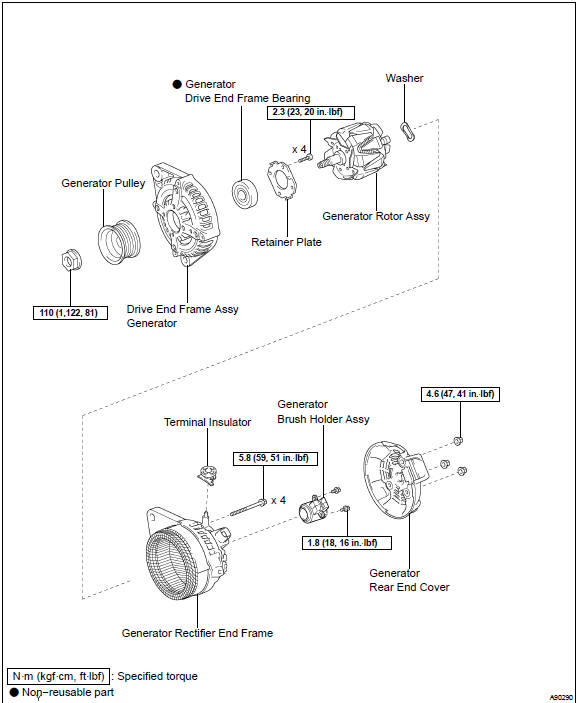
COMPONENTS
REPLACEMENT
-
REMOVE DRIVE BELT
-
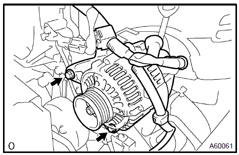
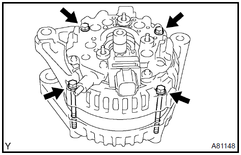
REMOVE GENERATOR ASSY
-
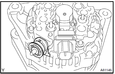
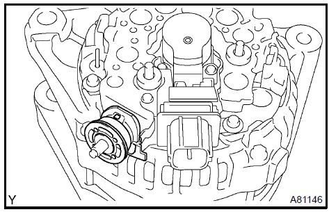
Disconnect the engine wire as shown in the illustration.
-
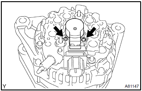
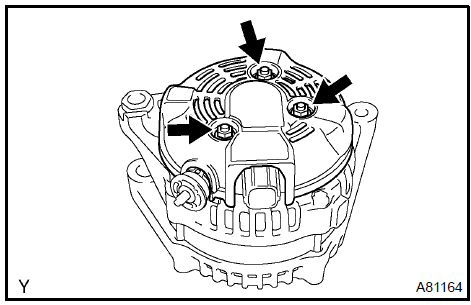
Remove the 2 bolts and generator.
 Remove generator assy
3. INSTALL GENERATOR ASSY
-
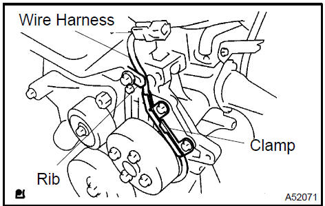
Confirm that the wire harness of the crankshaft position sensor is placed as shown in the illustration.
-
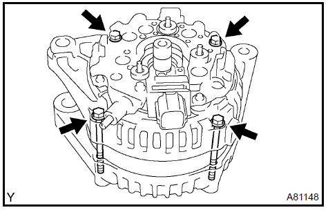
Install the generator.
Torque: 21 N·m (214 kgf·cm, 15 ft·lbf) for M8 52 N·m (530 kgf·cm, 38 ft·lbf) for M10 9 N·m (92 kgf·cm, 80 in.·lbf) for wiring harness clamp 9.8 N·m (100 kgf·cm, 7 ft·lbf) for generator wire
NOTICE: Be careful not to put the wire harness in when install the generator.
 Install generator assy
-
INSTALL DRIVE BELT
-
INSPECT DRIVE BELT
OVERHAUL
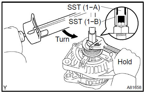
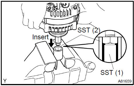
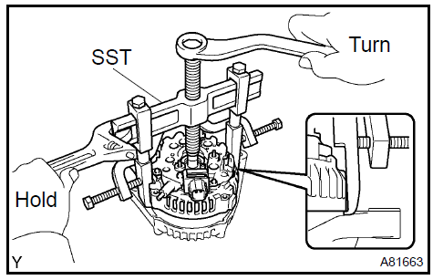
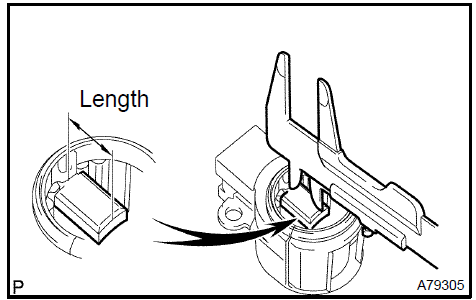
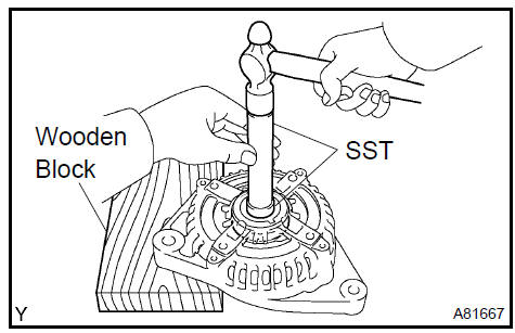
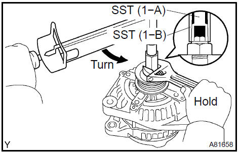
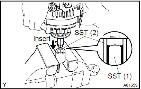
1. REMOVE GENERATOR PULLEY
SST 09820−63010 (09820−06010, 09820−06020)
HINT:

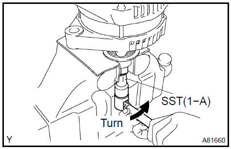
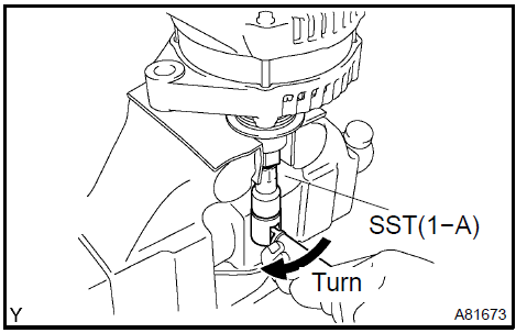
a. Hold SST (1−A) with a torque wrench, and tighten SST (1−B) clockΩise to the specified torque.
Torque: 39 N·m (400 kgf·cm, 29 ft·lbf)
NOTICE: Check that SST is secured to the rotor shaft.
-
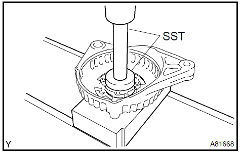
Clamp SST 2. in a vise.
-
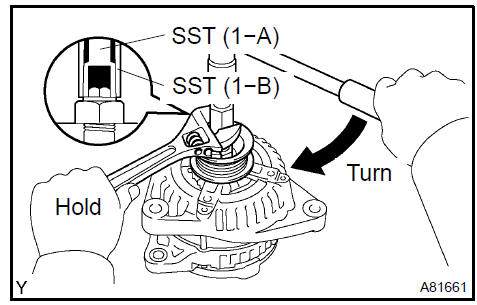
Insert SST (1−A, B) into SST 2., and attach the pulley nut to SST 2..
d. To loosen the pulley nut, turn SST (1−A) in the direction shown in the illustration.
NOTICE: To prevent damage to the rotor shaft, do not loosen the pulley nut more than one−half turn.
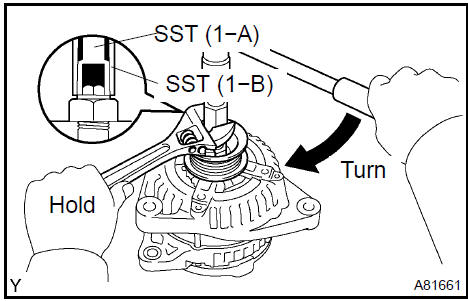
e. Remove the generator from SST 2..
-
Turn SST (1−B) and remove SST (1−A, B).
-
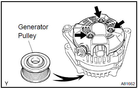
Remove the pulley nut and generator pulley.
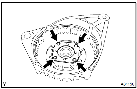
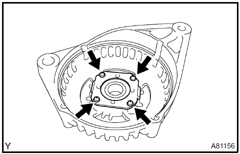
2. REMOVE GENERATOR REAR END COVER
-
Place the generator on the generator pulley.
-
Remove the 3 nuts and the generator rear end cover.
 ÁÞ
Remove generator rear end cover
ÁÞ
Remove generator rear end cover
3. REMOVE TERMINAL INSULATOR
a. Remove the terminal insulator from the generator rectifier end frame.
 ÁÞ
Remove terminal insulator
ÁÞ
Remove terminal insulator
4. REMOVE GENERATOR BRUSH HOLDER ASSY
a. Remove the 2 screws and the generator brush holder.
 ÁÞ
Remove generator brush holder assy
ÁÞ
Remove generator brush holder assy
5. REMOVE GENERATOR COIL ASSY
a. Remove the 4 bolts.
b. Using SST, remove the generator rectifier end frame.
SST 09950−40011 (09951−04020, 09952−04010, 09953−04020, 09954−04010, 09955−04071, 09957−04010, 09958−04011)
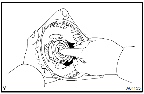
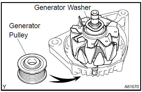
6. REMOVE GENERATOR ROTOR ASSY
a. Remove the generator washer and the generator rotor.
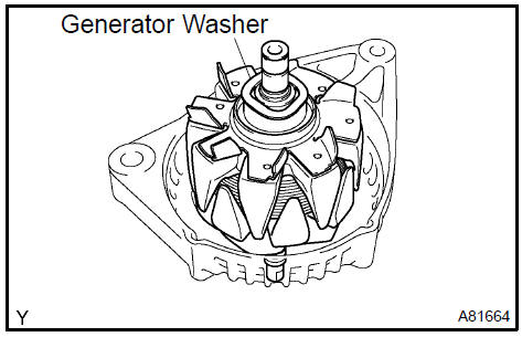 Remove generator rotor assy
7. INSPECT GENERATOR BRUSH HOLDER ASSY
a. Check the brush length.
1. Using a vernier caliper, measure the exposed brush length.
Specified brush length: 4.5 to10.5 mm (0.177 to 0.413 in.)
If the exposed brush length is less than minimum, replace the generator brush holder.
 Inspect generator brush holder assy
8. INSPECT GENERATOR ROTOR ASSY
a. Check the bearing is not rough or worn.
If necessary, replace the generator rotor.
b. Check the rotor for open circuit.
1. Using an ohmmeter, measure the resistance between the slip ring.
Standard: 2.3 to 2.7 W at 20 C (68 F)
If the resistance is not as specified, replace the generator rotor.
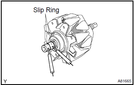
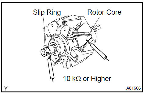
c. Check the rotor for ground.
1. Using an ohmmeter, check the resistance between the slip ring and the rotor core.
Standard: 10 kΩ or higher
If the resistance is not as specified, replace the generator rotor.
d. Inspect slip rings.
1. Check that the slip rings are not rough or scored.
If rough or scored, replace the generator rotor.
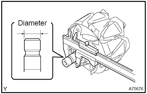
e. Check the slip ring diameter.
1. Using a vernier caliper, measure the slip ring diameter.
Specified diameter: 14.0 to 14.4 mm (0.551 to 0.567 in.)
If the diameter is less than minimum, replace the generator rotor.
9. INSPECT GENERATOR DRIVE END FRAME BEARING
a. Check the bearing is not rough or worn.
If necessary, replace the bearing.
 Inspect generator drive end frame bearing
10. REMOVE GENERATOR DRIVE END FRAME BEARING
a. Remove the 4 screws and the retainer plate.
b. Using SST, tap out the bearing.
SST 09950−60010 (09951−00250), 09950−70010 (09951−07100)
11. INSTALL GENERATOR DRIVE END FRAME BEARING
a. Using SST and a press, press in a new bearing.
SST 09950−60010 (09951−00470), 09950−70010 (09951−07100)
b. Install the retainer plate with the 4 screws.
Torque: 2.3 N·m (23 kgf·cm, 20 in.·lbf)
12. INSTALL GENERATOR ROTOR ASSY
-
Place the generator drive end frame on the generator pulley.
-
Install the generator rotor and the generator washer.
 Install generator rotor assy
13. INSTALL GENERATOR COIL ASSY
a. Using a deep socket wrench 21 and a press, press in the generator rectifier end frame carefully.
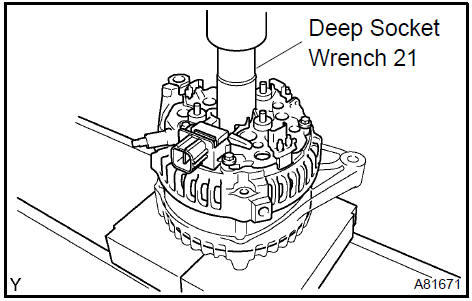
b. Tighten the 4 bolts.
Torque: 5.8 N·m (59 kgf·cm, 51 in.·lbf)
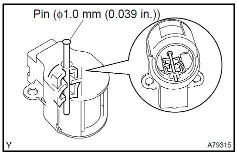
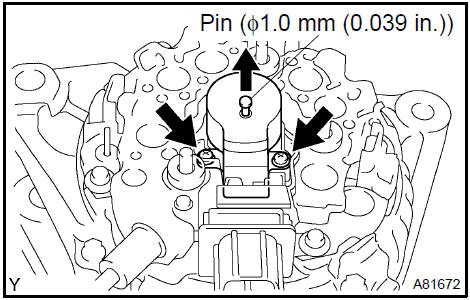
14. INSTALL GENERATOR BRUSH HOLDER ASSY
a. While pushing the 2 brushes to inside the brush holder, insert a pin (f1.0 mm (0.039 in.)) into the brush holder hole.
-
Install the generator brush holder with the 2 screws.
Torque: 1.8 N·m (18 kgf·cm, 16 in.·lbf)
-
Pull out the pin (f1.0 mm (0.039 in.)) from the generator brush holder.
15. INSTALL TERMINAL INSULATOR
a. Install the terminal insulator to the generator rectifier end frame.
NOTICE: Pay attention the mounting orientation of the terminal insulator.
 Install terminal insulator
16. INSTALL GENERATOR REAR END COVER
a. Install the generator rear end cover with the 3 nuts.
Torque: 4.6 N·m (47 kgf·cm, 41 in.·lbf)
 Install generator rear end cover
17. INSTALL GENERATOR PULLEY
SST 09820−63010 (09820−06010, 09820−06020)
HINT:
-
Install the generator pulley to the rotor shaft by tightening the pulley nut by hand.
-
Hold SST (1−A) with a torque wrench, and tighten SST (1−B) clockΩise to the specified torque.
Torque: 39 N·m (400 kgf·cm, 29 ft·lbf)
NOTICE: Check that SST is secured to the rotor shaft.
-
Clamp SST 2 in a vise.
-
Insert SST (1−A, B) into SST 2., and attach the pulley nut to SST 2.
-
Tighten the pulley nut by turning SST (1−A) in the direction shown in the illustration.
Torque: 111 N·m (1,125 kgf·cm, 81 ft·lbf)
-
Remove the generator from SST 2..
-
Turn SST (1−B), and remove SST (1−A, B).
-
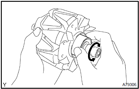
Turn the generator pulley and check that the generator pulley moves smoothly.
Starting system (2AZ−FE)(From July, 2003)
Charging system (2AZ−FE)(From July, 2003)
Generator assy (2AZ−FE)(From July, 2003)
Starting system (1MZ−FE/3MZ−FE)
Ignition or starter switch assy (1MZ−FE/3MZ−FE)
Starter assy (1MZ−FE/3MZ−FE)
Ignition or starter switch assy (2AZ−FE)(From July, 2003)
Starter assy (1MZ−FE/3MZ−FE)
Charging system (1MZ−FE/3MZ−FE)
Starter assy (2AZ−FE)(From July, 2003)
Generator assy (1MZ−FE/3MZ−FE)
Starter assy (2AZ−FE)(From July, 2003)
Toyota Camry XV30 (2002–2006) Service Manual
- Introduction
- Audio & visual system
- Automatic transmission / trans
- Brake
- Clutch
- Communication system
- Cooling
- Cruise control
- Drive shaft / propeller shaft
- Emission control
- Engine control system
- Engine hood/door
- Engine mechanical
- Exhaust
- Exterior/interior trim
- Front suspension
- Fuel
- Heater & air conditioner
- Ignition
- Instrument panel/meter
- Intake
- Lighting
- Lubrication
- Manual transmission/transaxle
- Parking brake
- Power steering
- Rear suspension
- Seat
- Service specifications
- Sliding roof/convertible
- Starting & charging
- Steering column
- Supplemental restraint system
- Theft deterrent & door lock
- Tire & wheel
- Windshield/windowglass/mirror
- Wiper & washer
- Wiring
Categories
