 Toyota Camry XV30 (2002–2006) Service ManualLubrication
Oil pump assy 1MZ−FE/3MZ−FE)
Oil pump assy 1MZ−FE/3MZ−FE)
REPLACEMENT
- REMOVE FRONT WHEEL RH
- REMOVE FRONT FENDER APRON SEAL RH
- REMOVE ENGINE UNDER COVER RH
- DRAIN ENGINE OIL
a. Install a new gasket after draining engine oil. Torque: 45 N·m (459 kgf·cm, 33 ft·lbf)
- REMOVE FRONT SUSPENSION UPPER BRACE CENTER (W/ FRONT SUSPENSION BRACE UPPER CENTER)
- REMOVE V BELT No. 1
- REMOVE VANE PUMP V BELT
- REMOVE ENGINE MOVING CONTROL ROD
- REMOVE ENGINE MOUNTING STAY No.2 RH
- REMOVE GENERATOR BRACKET No.2
- REMOVE CRANKSHAFT PULLEY
- REMOVE TIMING BELT No.1 COVER
- REMOVE TIMING BELT No.2 COVER
- REMOVE TIMING BELT GUIDE No.2
- REMOVE TIMING BELT
- REMOVE EXHAUST PIPE No.1 SUPPORT BRACKET
- REMOVE EXHAUST PIPE ASSY FRONT
- REMOVE EXHAUST PIPE SUPPORT BRACKET No.1
- SEPARATE COMPRESSOR AND MAGNETIC CLUTCH
a. Remove the 2 bolts, nut and the drive belt adjusting bar bracket.
- Remove the 2 nuts, the generator bracket adjusting bar with wire harness clamp bracket.
- Disconnect the compressor, magnetic clutch connector and the wire harness clamp.
d. Remove the 3 bolts, the compressor and magnetic clutch.
HINT: Hang up the hoses instead of detaching.
- REMOVE TIMING BELT IDLER SUB−ASSY No.2
- REMOVE CAMSHAFT TIMING PULLEY
- REMOVE TIMING BELT IDLER SUB−ASSY No.1
a. Using a 10 mm socket hexagon wrench, remove the timing belt idler and plate washer.
- REMOVE CRANKSHAFT TIMING PULLEY
- REMOVE TIMING BELT No.3 COVER
- REMOVE COMPRESSOR MOUNTING BRACKET
No.1 a. Remove the 2 bolts and mounting bracket.
 Remove compressor mounting bracket
26. REMOVE OIL LEVEL GAGE GUIDE
a. Remove the bolt and gage guide.
27. SEPARATE ENGINE MOUNTING INSULATOR FR
a. Remove the 3 nuts and bolt. Then separate the engine mounting insulator.
NOTICE: Do not remove the engine mounting insulator.
 Separate engine mounting insulator FR
28. REMOVE ENGINE MOUNTING INSULATOR RH
- Remove the bolt and disconnect the power steering return hose clamp from the frame.
- Remove the 4 nuts.
- Prepare a jack. Place a wooden block on the jack and set the jack under the engine. Remove the engine mounting insulator.
- Raise the jack and lift up the engine. Then remove the engine mounting insulator RH.
NOTICE: Be careful not to damage the contact surfaces of the oil pan.
 Remove engine mounting insulator RH
29. REMOVE ENGINE MOUNTING BRACKET RH
a. Remove the 4 bolts, nut and bracket.
 Remove engine mounting bracket RH
30. REMOVE OIL PAN SUB−ASSY No.2
a. Remove the 10 bolts, 2 nuts and oil pan.
b. Insert the blade of SST between the oil pan No. 1 and oil pan No. 2, cut through the sealer and remove oil pan No.
2.
SST 09032−00100
NOTICE:
- Do not damage the contact surface of oil pan No. 1 and oil pan No. 2.
- Do not damage the flange portion of oil pan No.2 during removal.
31. REMOVE OIL STRAINER SUB−ASSY
a. Remove the bolt and 2 nuts, and remove the oil strainer and gasket.
32. REMOVE OIL PAN SUB−ASSY
a. Remove the 2 bolts and the flywheel housing under cover.
b. Uniformly loosen the 17 bolts and 2 nuts. Remove the bolts and nuts.
c. Using a screwdriver, remove the oil pan by prying the portions between the cylinder block and oil pan shown in the illustration.
NOTICE: Be careful not to damage the contact surfaces of the cylinder block and oil pan.
33. REMOVE CRANKSHAFT POSITION SENSOR
- Disconnect the sensor connector.
- Remove the bolt and sensor.
34. REMOVE OIL PUMP ASSY
- Remove the 9 bolts.
- Using a screwdriver, remove the oil pump by prying between the oil pump and the main bearing cap.
- Remove the O−ring.
 Remove oil pump assy
35. INSTALL OIL PUMP ASSY
a. Using SST and a hammer, install a new oil seal. Tap the surface of the SST with the hammer until the oil seal’s surface is flush with oil pump body edge.
SST 09223−00010
NOTICE:
- Be careful not to tap the oil seal at an angle.
- Keep the gap between the oil pump body edge and the oil seal free from contamination.
- Apply a small amount of MP grease to the oil seal lip.
- Remove any old seal packing material from the contact surface.
d. Apply a light coat of engine oil to a new O−ring and place it on the cylinder block.
e. Apply a continuous bead of seal packing (diameter 2 to 3 mm (0.08 to 0.12 in.)) as shown in the illustration.
Seal packing: Part No. 08226−00080 or equivalent
NOTICE:
- Remove any oil from contact surface.
- Apply seal packing to the inner side of the bolt holes.
- Install the oil pump within 3 minutes after applying seal packing.
- Do not expose the seal to engine oil for at least 2 hours after installing the oil pump.
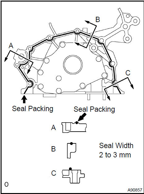
f. Align the key of the oil pump drive gear with the key way located on the crankshaft, and slide the oil pump into place.
g. Install the oil pump by tightening the 9 bolts uniformly.
Torque: 8.0 N·m (82 kgf·cm, 71 in.·lbf) for bolt A 20 N·m (203 kgf·cm, 15 ft·lbf) for bolt B 43 N·m (439 kgf·cm, 32 ft·lbf) for bolt C
- INSTALL CRANKSHAFT POSITION SENSOR Torque: 8 N·m (82 kgf·cm, 71 in.·lbf)
- INSTALL OIL PAN SUB−ASSY
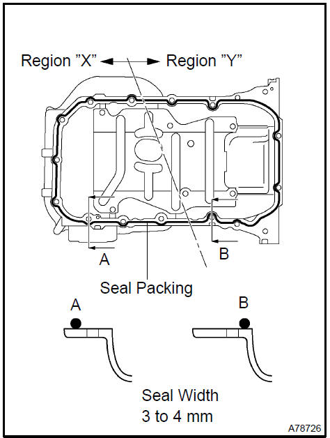
- Remove any old seal packing from the contact surface.
- Apply a continuous bead of seal packing (diameter 3 to
4 mm (0.12 to 0.16 in.)) as shown in the illustration.
Seal packing: Part No. 08826−00080 or equivalent
NOTICE:
- Remove any oil from the contact surface.
- Apply seal packing to the outer side of the bolt holes in the region ”X”.
- Apply seal packing to the inner side of the bolt holes in the region ”Y”.
- Install the oil pan within 3 minutes after applying seal packing.
- Do not expose the seal to engine oil for at least 2 hours after installing the oil pan.
- Install the oil pan No.1 by tightening the oil pan’s 17 bolts
and 2 nuts uniformly.
Torque: 8.0 N·m (82 kgf·cm, 71 in.·lbf) for 10 mm head 20 N·m (204 kgf·cm, 15 ft·lbf) for 12 mm head 37 N·m (379 kgf·cm, 27 ft·lbf) for 14 mm head
- Install the flywheel housing under cover with the 2 bolts.
Torque: 7.8 N·m (80 kgf·cm, 69 in.·lbf)
 Install oil pan sub-assy
38. INSTALL OIL STRAINER SUB−ASSY
a. Install a new gasket and the oil strainer with the bolt and 2 nuts.
Torque: 8 N·m (82 kgf·cm, 71 in.·lbf)
39. INSTALL OIL PAN SUB−ASSY No.2
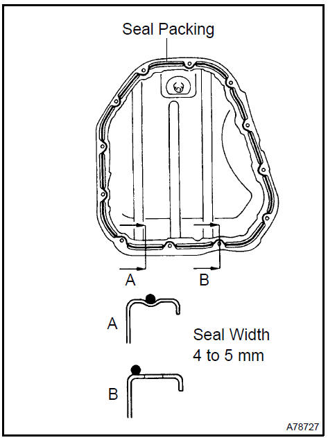
- Remove any old seal packing from the contact surface.
- Apply a continuous bead of seal packing (diameter 4 to
5 mm (0.16 to 0.20 in.)) as shown in the illustration.
Seal packing: Part No. 08826−00080 or equivalent
NOTICE:
- Remove any oil from the contact surface.
- Apply seal packing to the inner side of the bolt holes.
- Install the oil pan within 3 minutes after applying seal packing.
- Do not expose the seal to engine oil for at least 2 hours after installing the oil pan.
c. Install the oil pan with the 10 bolts and 2 nuts.
Torque: 8.0 N·m (82 kgf·cm, 71 in.·lbf)
 Install oil pan sub-assy No.2
40. INSTALL ENGINE MOUNTING BRACKET RH
Torque:
54 N·m (550 kgf·cm, 40 ft·lbf) for bolt A
54 N·m (550 kgf·cm, 40 ft·lbf) for nut B
43 N·m (439 kgf·cm, 32 ft·lbf) for bolt C
 Install engine mounting bracket RH
41. INSTALL ENGINE MOUNTING INSULATOR RH
Torque:
95 N·m (969 kgf·cm, 70 ft·lbf) for nut A
87 N·m (887 kgf·cm, 64 ft·lbf) for nut B
 Install engine mounting insulator RH
42. INSTALL ENGINE MOUNTING INSULATOR FR
Torque:
87 N·m (887 kgf·cm, 64 ft·lbf) for bolt A
52 N·m (531 kgf·cm, 38 ft·lbf) for nut B
 Install engine mounting insulator FR
43. INSTALL OIL LEVEL GAGE GUIDE
a. Install a new O−ring, bolt and gage guide. Torque: 8 N·m (82 kgf·cm, 71 in.·lbf)
- INSTALL COMPRESSOR MOUNTING BRACKET No.1 Torque: 25 N·m (250 kgf·cm, 18 ft·lbf)
- INSTALL TIMING BELT No.3 COVER
- INSTALL TIMING BELT IDLER SUB−ASSY No.1
a. Using a 10 mm hexagon wrench, install the plate washer and idler pulley with the pivot bolt. Torque: 34 N·m (347 kgf·cm, 25 ft·lbf)
- INSTALL TIMING BELT IDLER SUB−ASSY No.2
- INSTALL CAMSHAFT TIMING PULLEY
- INSTALL COMPRESSOR AND MAGNETIC CLUTCH Torque: 25 N·m (250 kgf·cm, 18 ft·lbf)
- INSTALL EXHAUST PIPE SUPPORT BRACKET No.1
- INSTALL EXHAUST PIPE ASSY FRONT
- INSTALL EXHAUST PIPE No.1 SUPPORT BRACKET
- INSPECT TIMING BELT
- INSTALL TIMING BELT
- INSTALL TIMING BELT GUIDE No.2
- INSTALL TIMING BELT No.2 COVER
- INSTALL TIMING BELT No.1 COVER
- INSTALL CRANKSHAFT PULLEY
- INSTALL GENERATOR BRACKET No.2 Torque: 28 N·m (286 kgf·cm, 21 in.·lbf)
- INSTALL ENGINE MOUNTING STAY No.2 RH
- INSTALL ENGINE MOVING CONTROL ROD
- INSTALL VANE PUMP V BELT
- INSTALL V BELT No. 1
- INSPECT DRIVE BELT TENSION
- INSTALL FRONT SUSPENSION UPPER BRACE CENTER (W/ FRONT SUSPENSION BRACE UPPER CENTER) Torque: 80 N·m (816 kgf·cm, 59 ft·lbf)
- ADD ENGINE OIL
- INSPECT CHECK FOR ENGINE OIL LEAKS
- INSTALL FRONT WHEEL RH
- CHECK FOR EXHAUST GAS LEAKS
OVERHAUL
1. REMOVE OIL PUMP RELIEF VALVE
a. Remove the plug, spring and relief valve.
2. INSPECT OIL PUMP RELIEF VALVE
- Apply a light coat of engine oil.
- Check that the valve falls smoothly into the valve hole by its own weight.
If it does not, replace the relief valve. If necessary, replace the oil pump assy.
 Inspect oil pump relief valve
3. INSPECT OIL PUMP COVER
a. Remove the 10 screws and the oil pump cover.
4. INSPECT OIL PUMP ROTOR
a. Apply a light coat of engine oil to the oil pump rotor set and place them into the oil pump body. Check that the rotors revolve smoothly.
If the result is not as specified, replace the oil pump assy.
b. Check the clearance between the drive tips and driven rotor grooves.
1. Insert a feeler gauge between each drive tip and driven rotor groove. Measure the clearances.
Specified tip clearance: 0.060 to 0.300 mm (0.0024 to 0.0118 in.)
If the tip clearance is greater than the maximum, replace the oil pump assy.
c. Check the clearance between the driven rotor and body.
1. Insert a feeler gauge between the driven rotor and body. Measure the clearance.
Specified body clearance: 0.250 to 0.500 mm (0.0098 to 0.0128 in.)
If the body clearance is greater than the maximum, replace the oil pump assy.
d. Check the clearance between the drive and driven rotor.
1. Place a precision straight edge on the top surface of the drive. Insert a feeler gauge between the bottom edge of the precision straight edge and the top surface of the driven rotor. Measure the clearance.
Specified side clearance: 0.030 to 0.150 mm (0.0012 to 0.0059 in.)
If the side clearance is greater than the maximum, replace the oil pump assy.
- REMOVE OIL PUMP ROTOR
- INSTALL OIL PUMP ROTOR
a. Apply a light coat of engine oil to the oil pump gear set and place it into the pump body with the marks facing the pump body cover side.
 Install oil pump rotor
7. INSTALL OIL PUMP COVER
a. Install the oil pump cover with the 10 screws.
Torque: 10 N·m (102 kgf·cm, 7 ft·lbf)
8. INSTALL OIL PUMP RELIEF VALVE
- Apply a light coat of engine oil to the relief valve, and insert the relief valve and spring into the pump body hole.
- Install the plug.
Torque: 49 N·m (500 kgf·cm, 36 ft·lbf)
Lubrication system (2AZ−FE)(From July, 2003)
Oil pump assy (2AZ−FE)(From July, 2003)
Lubrication system (1MZ−FE/3MZ−FE)
Oil filter sub-assy (1MZ−FE/3MZ−FE)
Oil pump assy (1MZ−FE/3MZ−FE)
Oil filter sub-assy (2AZ−FE)(From July, 2003)
Oil pump assy 1MZ−FE/3MZ−FE)
Oil pump assy (2AZ−FE)(From July, 2003)
Outside vehicle
Inside vehicle
Under hood
Engine
Brake
Chassis
Body
Toyota Camry XV30 (2002–2006) Service Manual
- Introduction
- Audio & visual system
- Automatic transmission / trans
- Brake
- Clutch
- Communication system
- Cooling
- Cruise control
- Drive shaft / propeller shaft
- Emission control
- Engine control system
- Engine hood/door
- Engine mechanical
- Exhaust
- Exterior/interior trim
- Front suspension
- Fuel
- Heater & air conditioner
- Ignition
- Instrument panel/meter
- Intake
- Lighting
- Lubrication
- Manual transmission/transaxle
- Parking brake
- Power steering
- Rear suspension
- Seat
- Service specifications
- Sliding roof/convertible
- Starting & charging
- Steering column
- Supplemental restraint system
- Theft deterrent & door lock
- Tire & wheel
- Windshield/windowglass/mirror
- Wiper & washer
- Wiring
Categories
