 Toyota Camry XV30 (2002–2006) Service ManualLighting
Headlamp assy LH
Headlamp assy LH
ADJUSTMENT
1. VEHICLE PREPARATION FOR HEADLAMP AIM ADJUSTMENT
a. Prepare the vehicle:
- Ensure there is no damage or deformation to the body around the headlamps.
- Fill the fuel tank.
- Make sure that the oil is filled to the specified level.
- Make sure that the coolant is filled to the specified level.
- Inflate the tires to the appropriate pressure.
- Place the spare tire, tools, and jack in their original positions.
- Unload the trunk.
- Sit a person of average weight (68 kg, 150 lb) in the driver’s seat.
2. PREPARATION FOR HEADLAMP AIMING (Using a tester)
- Prepare the vehicle for headlamp aim check.
- Adjust in accordance with headlamp tester instructions.
3. PREPARATION FOR HEADLAMP AIMING (Using a screen)
a. Prepare the vehicle according to the following conditions:
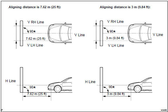
- Place the vehicle in a location that is dark enough to clearly observe the cutoff line. The cutoff line is a distinct line, below which light from the headlamps can be observed and above which it cannot.
- Place the vehicle at a 90 angle to the wall.
- Create a 7.62 m (25 ft) distance between the vehicle (headlamp bulb center) and the wall.
- Place the vehicle on a level surface.
- Bounce the vehicle up and down to settle the suspension.
 Preparation for headlamp aiming
NOTICE: A distance of 7.62 m (25 ft) between the vehicle (headlamp bulb center) and the wall is necessary for proper aim adjustment.
If unavailable, secure a distance of exactly 3 m (9.84 ft) for check and adjustment. (The target zone will change with the distance so follow the instructions in the illustration.)
- Prepare a piece of thick white paper (approximately 2 m (6.6 ft) (height) x 4 m (13.1 ft) (width)) to use as a screen.
- Draw a vertical line down the center of screen (V line).
- Set the screen as shown in the illustration.
HINT:
- Stand the screen perpendicular to the ground.
- Align the V line on the screen with the center of the vehicle.
e. Draw base lines (H line, V LH, V RH lines) on the screen as shown in the illustration.
HINT:
- The base lines differ for ”low−beam inspection” and ”high−beam inspection”.
- Mark the headlamp bulb center marks on the screen. If the center mark cannot be observed on the headlamp, use the center of the headlamp bulb or the manufacturer’s name marked on the headlamp as the center mark.
- H Line (Headlamp height): Draw a horizontal line across the screen so that it passes through the center marks. The H line should be at the same height as the headlamp bulb center marks of the low−beam headlamps.
- V LH Line, V RH Line (Center mark position of left− hand (LH) and right−hand (RH) headlamps): Draw two vertical lines so that they intersect the H line at each center mark (aligned with the center of the low−beam headlamp bulbs).
4. HEADLAMP AIMING INSPECTION
a. Cover or disconnect the connector of the headlamp on the opposite side to prevent light from the headlamp not being inspected from affecting headlamp aiming inspection.
NOTICE: Do not keep the headlamp covered for more than 3 minutes. The headlamp lens is made of synthetic resin, and may easily melt or be damaged due to heat.
HINT: When checking the aim of the high−beam, cover the low−beam or disconnect the connector.
b. Start the engine.
NOTICE: Engine rpm must be 1,500 or more.
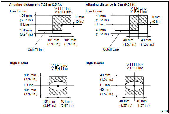
c. Turn on the headlamp and make sure that the cutoff line falls within the specified area, as shown in the illustration.
HINT:
- Since the low−beam light and the high−beam light are a unit, if the aim on one is correct, the other should also be correct. However, check both beams just to make sure.
- Alignment distance is 7.62 m (25 ft): The cutoff line is 101 mm (3.97 in.) above and below the H line as well as left and right of the V line with low−beam (SAE J599).
- Alignment distance is 3 m (9.84 ft): The cutoff line is 40 mm (1.57 in.) above and below the H line as well as left and right of the V line with low−beam (SAE J599).
- Alignment distance is 7.62 m (25 ft): The cutoff line is 101 mm (3.97 in.) above and below the H line as well as left and right of the V line with high−beam (SAE J599).
- Alignment distance is 3 m (9.84 ft): The cutoff line is 40 mm (1.57 in.) above and below the H line as well as left and right of the V line with high−beam (SAE J599).
- Alignment distance is 7.62 m (25 ft): The cutoff line is 53 mm (2.08 in.) below the H line with low−beam.
- Alignment distance is 3 m (9.84 ft): The cutoff line is 21 mm (0.82 in.) below the H line with low−beam.
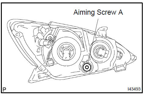
5. HEADLAMP AIMING ADJUSTMENT
a. Adjust the aim vertically: Adjust the headlamp aim into the specified range by turning aiming screw A with a screwdriver.
NOTICE: The final turn of the aiming screw should be made in the clockΩise direction. If the screw is tightened excessively, loosen it and then retighten it, so that the final turn of the screw is in the clockΩise direction.
HINT:
- Perform low−beam aim adjustment.
- The headlamp aim moves up when turning the aiming screw clockΩise, and moves down when turning the aiming screw counterclockΩise.
 Headlamp aiming adjustment
REPAIR
HINT:
- COMPONENTS:
- Use the same procedures for the RH side and LH side.
- The procedures listed below are for the LH side.
- If the area where the headlamp unit LH is installed is broken, the repairs listed below can be performed inexpensively through the use of a repair use bracket. This may only be done if the headlamp assy LH itself is not damaged.
- REMOVE FRONT BUMPER ASSY
- REMOVE HEADLAMP ASSY LH
- INSTALL HEADLAMP PROTECTOR RETAINER UPPER LH
HINT:
- If the installation area of the headlamp assy LH is damaged, use the supply bracket for low−cost repair.
- Ensure that the headlamp assy LH is not damaged.
a. Cut off the part shaded in the illustration and sand smooth with sandpaper.
NOTICE: After cutting off the part, place the headlamp protector retainer UPPER LH against the bosses and gradually file away until installation is possible.
b. Install the headlamp protector retainer UPPER LH with the 2 screws.
- VEHICLE PREPARATION FOR HEADLAMP AIM ADJUSTMENT
- PREPARATION FOR HEADLAMP AIMING (Using a screen)
- HEADLAMP AIMING INSPECTION
- HEADLAMP AIMING ADJUSTMENT
- VEHICLE PREPARATION FOR FOG LAMP AIM ADJUSTMENT
- PREPARATION FOR FOG LAMP AIMING
- FOG LAMP AIMING INSPECTION
- FOG LAMP AIMING ADJUSTMENT
Lighting system
Headlamp assy LH
Fog lamp assy LH
Lighting system
Rear combination lamp assy LH
License plate lamp assy
Center stop lamp assy
Headlamp dimmer switch assy
Lighting system
Headlamp assy LH
Toyota Camry XV30 (2002–2006) Service Manual
- Introduction
- Audio & visual system
- Automatic transmission / trans
- Brake
- Clutch
- Communication system
- Cooling
- Cruise control
- Drive shaft / propeller shaft
- Emission control
- Engine control system
- Engine hood/door
- Engine mechanical
- Exhaust
- Exterior/interior trim
- Front suspension
- Fuel
- Heater & air conditioner
- Ignition
- Instrument panel/meter
- Intake
- Lighting
- Lubrication
- Manual transmission/transaxle
- Parking brake
- Power steering
- Rear suspension
- Seat
- Service specifications
- Sliding roof/convertible
- Starting & charging
- Steering column
- Supplemental restraint system
- Theft deterrent & door lock
- Tire & wheel
- Windshield/windowglass/mirror
- Wiper & washer
- Wiring
Categories
