 Toyota Camry XV30 (2002–2006) Service ManualIntake
Intake manifold runner valve assy (2AZ−FE (PZEV))
(From July, 2003)
Toyota Camry
XV30 (2002–2006) Service Manual
Intake manifold runner valve assy (2AZ−FE (PZEV)) (From July, 2003)
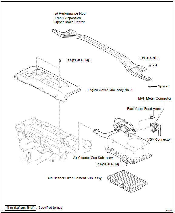
COMPONENTS
REPLACEMENT
- DRAIN ENGINE COOLANT
- REMOVE FRONT SUSPENSION UPPER BRACE CENTER (W/ PERFORMANCE ROD)
- REMOVE ENGINE COVER SUB−ASSY No.1
a. Remove the 2 nuts and engine cover.
 Remove engine cover sub-assy No.1
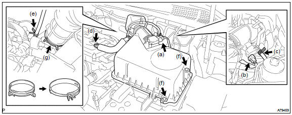
4. REMOVE AIR CLEANER CAP SUB−ASSY
- Disconnect the MAF meter connector.
- Disconnect the VSV connector.
- Disconnect the fuel vapor feed hose No. 2.
- Disconnect the ventilation hose.
- Disconnect the fuel vapor feed hose No. 1.
- Loosen the 2 air cleaner cap bolts.
- Lock the air cleaner hose clamp and remove the air cleaner cap together with the air cleaner hose.
 Remove air cleaner cap sub-assy
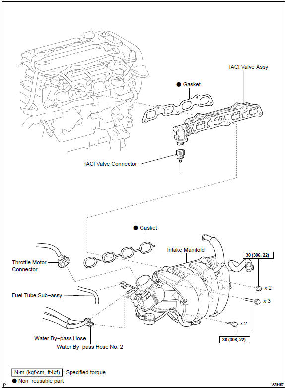
5. REMOVE INTAKE MANIFOLD
- Disconnect the ventilation hose No. 2.
- Disconnect the union to connector tube hose.
- Disconnect the throttle motor connector.
- Remove the wire harness from the wire harness clamp.
- Remove the fuel tube from the fuel pipe support.
- Disconnect the water by−pass hose No. 2
- Disconnect the water by−pass hose.
- In order to remove the intake manifold, Uniformly remove the 5 bolts and 2 nuts in the sequence shown in the illustration.
- Remove the gasket from the intake manifold.
6. REMOVE INTAKE AIR CONTROL VALVE ASSY
- Disconnect the IAC valve connector.
- Remove the IAC valve and gasket from the cylinder head.
7. INSTALL INTAKE AIR CONTROL VALVE ASSY
- Install a new gasket and the IAC valve to the cylinder head.
- Connect the IAC valve connector.
8. INSTALL INTAKE MANIFOLD
- Install a new gasket to the intake manifold.
- Install the intake manifold with the 5 bolts and 2 nuts. Uniformly
tighten the bolts and nuts in the sequence shown
in the illustration.
Torque: 30 N·m (306 kgf·cm, 22 ft·lbf)
- Connect the water by−pass hose.
- Connect the water by−pass hose No. 2
- Install the fuel tube to the fuel pipe support.
- Install the wire harness to the wire harness clamp.
- Connect the throttle motor connector.
- Connect the union to connector tube hose.
- Connect the ventilation hose No. 2.
- INSTALL AIR CLEANER CAP SUB−ASSY Torque: 5.0 N·m (51 kgf·cm, 44 in.·lbf)
- ADD ENGINE COOLANT
- CHECK FOR ENGINE COOLANT LEAKS
- INSTALL ENGINE COVER SUB−ASSY No.1 Torque: 7.0 N·m (71 kgf·cm, 62 in.·lbf)
- INSTALL FRONT SUSPENSION UPPER BRACE CENTER (W/ PERFORMANCE ROD) Torque: 80 N·m (815 kgf·cm, 59 ft·lbf)
More about «Intake»:
Intake air control system (2AZ−FE (PZEV)) (From July, 2003)
Intake air control valve assy No.1 (1MZ−FE)
Intake air control valve assy No.2 (1MZ−FE/3MZ−FE)
Intake air control system (2AZ−FE (PZEV)) (From July, 2003)
Intake manifold runner valve assy (2AZ−FE (PZEV)) (From July, 2003)
Intake air control system (1MZ−FE/3MZ−FE)
Toyota Camry XV30 (2002–2006) Service Manual / Intake / Intake manifold runner valve assy (2AZ−FE (PZEV))
(From July, 2003)
Toyota Camry XV30 (2002–2006) Service Manual
- Introduction
- Audio & visual system
- Automatic transmission / trans
- Brake
- Clutch
- Communication system
- Cooling
- Cruise control
- Drive shaft / propeller shaft
- Emission control
- Engine control system
- Engine hood/door
- Engine mechanical
- Exhaust
- Exterior/interior trim
- Front suspension
- Fuel
- Heater & air conditioner
- Ignition
- Instrument panel/meter
- Intake
- Lighting
- Lubrication
- Manual transmission/transaxle
- Parking brake
- Power steering
- Rear suspension
- Seat
- Service specifications
- Sliding roof/convertible
- Starting & charging
- Steering column
- Supplemental restraint system
- Theft deterrent & door lock
- Tire & wheel
- Windshield/windowglass/mirror
- Wiper & washer
- Wiring
Categories

© 2011-2026 Copyright www.tcamanual.com