 Toyota Camry XV30 (2002–2006) Service ManualEngine control system
SFI system (1MZ−FE/3MZ−FE)
SFI system (1MZ−FE/3MZ−FE)
ON−VEHICLE INSPECTION
1. CHECK THROTTLE BODY
a. Listen to the throttle control motor operating sounds.
-
Turn the ignition switch ON.
-
When pressing the accelerator pedal position lever, listen to the running motor. Make sure no friction noise comes from the motor.
If friction noise exists, replace the throttle body.
b. Inspect the throttle position .
-
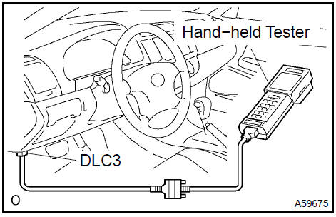
Connect the hand−held tester or OBD II scan tool to the DLC3.
-
Turn the ignition switch ON.
-
Check that the MIL is off.
-
Under CURRENT DATA, the throttle valve opening percentage (THROTTLE POS) should be within the standard value range below.
Standard throttle valve opening percentage: 60% or more
If the percentage is less than 60%, replace the throttle body.
NOTICE: When checking the standard throttle valve opening percentage, the transmission should be in the neutral position.
2. CHECK ACCELERATOR PEDAL POSITION
a. Turn the ignition switch ON. Under CURRENT DATA, the voltage of the throttle position should be within the standard value range below.
Standard: 0.6 to 1.0 V
If the result is not as specified, replace the accelerator pedal position .
3. CHECK CAMSHAFT TIMING OIL CONTROL VALVE ASSY
-
Connect the hand−held tester or OBD II scan tool to the DLC3.
-
Turn the ignition switch ON.
-
Start the engine and warm it up.
-
Select the VVT from the ACTIVE TEST menu.
-
Check the engine speed when the OCV is operated by the hand−held tester.
Standard
:

If the result is not as specified, replace the OCV assy.
4. CHECK MASS AIR FLOW METER (MAF meter)
NOTICE:
-
Perform the MAF meter inspection by following the procedures below.
-
Only replace the MAF meter when both the LONG FT#1 value and MAF value in the DATA LIST (with the engine stopped) are not within the normal operating range.
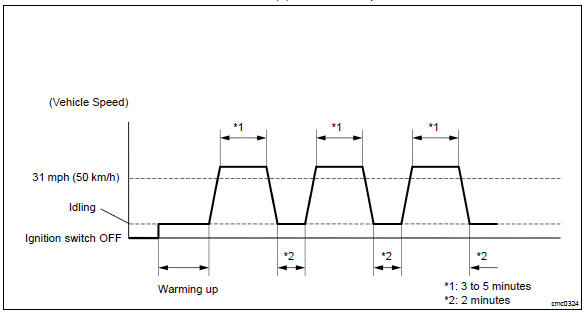
a. Perform confirmation driving pattern.
-
Connect the hand−held tester to the DLC3.
-
Turn the ignition switch ON.
-
Turn the tester on.
-
Clear the DTCs.
-
Start the engine and warm it up with all accessory switches off (until the engine coolant temperature is 75 C (167 F) or more).
-
Drive the vehicle at 31 mph (50 km/h) or more for 3 to 5 minutes. *1
-
Allow the engine to idle for 2 minutes. *2
-
Perform steps *1 and *2 at least 3 times.
b. Read value using the hand−held tester (LONG FT#1).
-
Select the following menu items: DIAGNOSIS / ENHANCED OBD II / DATA LIST / PRIMARY / LONG FT#1.
-
Read the values displayed on the tester.
Standard value:
Within −15 to +15 %
If the result is not within the specified range, perform the inspection below.
c. Read value using the hand−held tester (MAF).
NOTICE:
-
Turn off the engine.
-
Perform the inspection with the vehicle indoors and on a level surface.
-
Perform the inspection of the MAF meter while it is installed to the air cleaner case (installed to the vehicle).
-
During the test, do not use the exhaust air duct to perform suction on the exhaust pipe.
-
Turn off the engine (do not run the engine).
-
Turn the ignition switch ON.
-
Turn the tester on.
-
Select the following menu items: DIAGNOSIS / ENHANCED OBD II / DATA LIST / PRIMARY / PRIMARY / MAF.
-
Wait 30 seconds, and read the values on the hand− held tester.
Standard condition: Less than 0.54 g/s
-
If the result is not as specified, replace the MAF meter.
-
If the result is within the specified range, inspect the cause of the extremely rich or lean air fuel ratio (see page 05−632).
INSPECTION
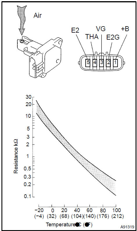
1. INSPECT MASS AIR FLOW METER
a. Check the output voltage.
-
Apply battery voltage across terminals 1 (+B) and 2 (E2G).
-
Using a voltmeter, connect the positive (+) tester probe to terminal VG, and negative (−) tester probe to terminal E2G.
-
Blow air into the MAF meter, and check that the voltage fluctuates.
b Measure the resistance between terminals 4 (THA) and 5 (E2).
Standard
:
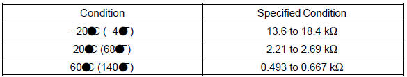
If the result is not as specified, replace the MAF meter.
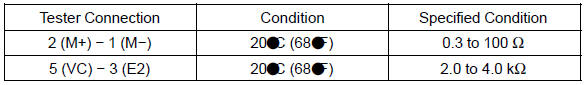
2. INSPECT CAMSHAFT TIMING OIL CONTROL VALVE ASSY
a. Measure the resistance between the terminals.
Standard: 6.9 to 7.9 W at 20 C (68 F)
If the result is not as specified, replace the OCV assy.
b. Connect the battery’s positive (+) lead to terminal 1 and negative (−) lead to terminal 2, and check the movement of the valve.
NOTICE: Confirm that the valve moves freely and does not become stuck in any position.
If necessary, replace the OCV assy.
HINT: If the valve cannot return properly because of foreign matter, a small pressure leak in the advanced direction may occur and a DTC will be output.
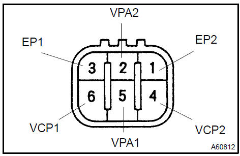
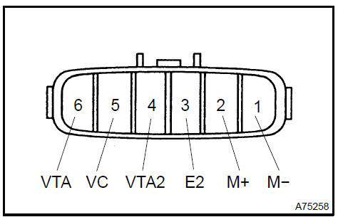
3. INSPECT ACCELERATOR PEDAL ASSY
a. Measure the resistance between the terminals.
Standard
:
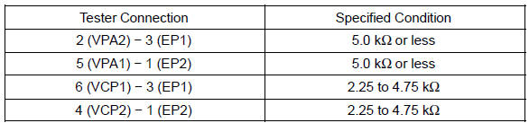
If the result is not as specified, replace the pedal assy.
4. INSPECT THROTTLE BODY ASSY
a. Measure the resistance between the terminals.
Standard
:
If the result is not as specified, replace the throttle body assy.
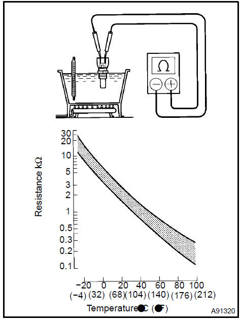
5. INSPECT ENGINE COOLANT TEMPERATURE
a. Measure the resistance between each terminal.
Standard
:
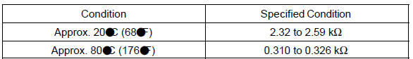
If the result is not as specified, replace the .
NOTICE: If checking the engine coolant temperature in the water, keep the terminals dry. After the check, wipe the dry.
6. INSPECT KNOCK (1MZ−FE ENGINE TYPE)
a. Using an ohmmeter, measure the resistance between the terminal and body.
Standard: 10 kW or higher
HINT: If the result is not as specified, replace the .
Inspect knock (1MZ-FE engine type)
7. INSPECT KNOCK (3MZ−FE ENGINE TYPE)
a. Using an ohmmeter, measure the resistance between the terminals.
Standard: 120 to 280 kW at 20 C (68 F)
HINT: If the result is not as specified, replace the .
8. INSPECT RELAY (Marking: EFI, C/OPN)
a. Using an ohmmeter, measure the resistance of the relay.
Standard
:
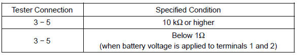
If the result is not as specified, replace the relay.
SFI system (2AZ−FE)
Accelerator pedal assy (2AZ−FE)
SFI system (1MZ−FE/3MZ−FE)
Throttle body assy (1MZ−FE/3MZ−FE)
SFI system (2AZ−FE)
Knock (1MZ−FE/3MZ−FE)
ECM (1MZ−FE/3MZ−FE)
Accelerator pedal assy (1MZ−FE/3MZ−FE)
Throttle body assy (2AZ−FE)
Knock (2AZ−FE)
ECM (2AZ−FE)
Toyota Camry XV30 (2002–2006) Service Manual
- Introduction
- Audio & visual system
- Automatic transmission / trans
- Brake
- Clutch
- Communication system
- Cooling
- Cruise control
- Drive shaft / propeller shaft
- Emission control
- Engine control system
- Engine hood/door
- Engine mechanical
- Exhaust
- Exterior/interior trim
- Front suspension
- Fuel
- Heater & air conditioner
- Ignition
- Instrument panel/meter
- Intake
- Lighting
- Lubrication
- Manual transmission/transaxle
- Parking brake
- Power steering
- Rear suspension
- Seat
- Service specifications
- Sliding roof/convertible
- Starting & charging
- Steering column
- Supplemental restraint system
- Theft deterrent & door lock
- Tire & wheel
- Windshield/windowglass/mirror
- Wiper & washer
- Wiring
Categories
