 Toyota Camry XV30 (2002–2006) Service ManualHeater & air conditioner
Air conditioning radiator assy
Air conditioning radiator assy
COMPONENTS
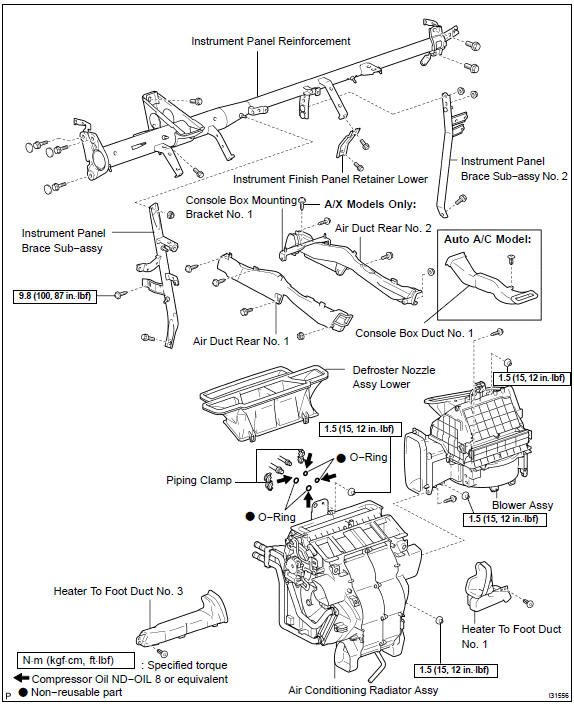
OVERHAUL
HINT: COMPONENTS:
- DISCHARGE REFRIGERANT FROM REFRIGERATION SYSTEM
SST 07110−58060 (07117−58080, 07117−58090, 07117−78050, 07117−88060, 07117−88070, 07117−88080)
- DISCONNECT COOLER REFRIGERANT SUCTION HOSE No.1
a. Install SST to piping clamp.
SST 09870−00015
HINT: Confirm the direction of the piping clamp claw and SST using the illustration showing on the caution label.
b. Push down SST and release the clamp lock.
NOTICE: Be careful not to deform the tube, when pushing SST.
c. Pull SST slightly and push the release lever, then remove the piping clamp with SST.
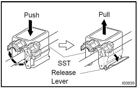
d. Disconnect the cooler refrigerant suction hose No. 1.
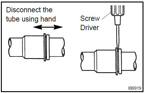
NOTICE:
- Do not use tools like screwdriver to remove the tube.
- Cap the open fittings immediately to keep moisture or dirt out of the system.
3. DISCONNECT COOLER REFRIGERANT LIQUID PIPE A
SST 09870−00025
HINT: Disconnect cooler refrigerant liquid pipe A in the same way as the cooler refrigerant suction hose No. 1.
4. DISCONNECT HEATER OUTLET WATER HOSE
a. Using pliers, grip the claws of clip and slide the clip and disconnect the heater outlet water hose.
 Disconnect heater outlet water hose
5. DISCONNECT HEATER INLET WATER HOSE
HINT: Disconnect in the same way as the heater outlet water hose.
6. REMOVE INSTRUMENT PANEL SAFETY PAD SUB−ASSY
HINT: Refer to the instructions for removal of the instrument panel safety pad sub−assy.
7. REMOVE AIR DUCT REAR No.1
a. Remove the 2 screws, bolt and nut.
b. Remove the air duct rear No. 1.
 Remove air duct rear No.1
8. REMOVE AIR DUCT REAR No.2
- Remove the bolt and nut.
- A/X models: Remove the 2 screws, air duct rear No. 2 and console box mounting bracket No. 1.
- M/X models: Remove the screw, air duct rear No. 2 and console box mounting bracket No. 1.
 Remove air duct rear No.2
9. REMOVE CONSOLE BOX DUCT No.1 (AUTO AIR CONDITIONING)
a. Remove the clip and console box duct No. 1.
 Remove console box duct No.1 (Auto air conditioning)
- DISCONNECT FLOOR SHIFT PARKING LOCK CABLE ASSY
- REMOVE WINDSHIELD WIPER RELAY ASSY
- REMOVE INSTRUMENT PANEL BRACE SUB−ASSY No.1
a. Remove the 2 bolts and 2 earth wires.
b. Release the 2 clamps.
- Remove the bolt and screw.
- Remove the nut and instrument panel brace sub−assy No. 1.
13. REMOVE INSTRUMENT FINISH PANEL RETAINER LOWER
a. Remove the 2 bolts and instrument finish retainer lower.
 Remove instrument finish panel retainer lower
14. REMOVE INSTRUMENT PANEL BRACE SUB−ASSY No.2
a. Remove the clamp, nut and passenger side junction block.
b. Remove the bolt and earth wire.
c. Remove the nut and clamp.
d. Remove the 2 nuts, bolt and instrument panel brace sub− assy No. 2.
15. REMOVE HEATER TO FOOT DUCT No.3
a. Remove the clip and heater to foot duct No. 3.
 Remove heater to foot duct No.3
16. REMOVE HEATER TO FOOT DUCT No.1
a. Remove the clip and heater to foot duct No. 1.
 Remove heater to foot duct No.1
17. DISCONNECT STEERING COLUMN ASSY
a. Remove the 3 nuts and driver side junction block.
b. Remove the 2 nuts and steering side connector block.
- Release the 2 clamps.
- Remove the 3 bolts, disconnect the steering column assy.
18. REMOVE INSTRUMENT PANEL REINFORCEMENT
a. Disconnect the 7 clamps and the wire harness.
b. Remove the 3 nuts, disconnect the 3 earth wires.
c. Remove the 3 caps, 7 bolts and instrument panel reinforcement.
19. REMOVE BLOWER ASSY
- Disconnect the connectors.
- Remove the screw, clamp and blower connector holder
c. Disconnect the 6 clamps and the wire harness.
d. Remove the 2 screws, 2 nuts and blower assy.
20. REMOVE DEFROSTER NOZZLE ASSY LOWER
a. Release the 4 fitting claws, remove the defroster nozzle assy lower.
 Remove defroster nozzle assy lower
21. REMOVE AIR CONDITIONING RADIATOR ASSY
- Disconnect the connectors.
- Remove the 2 nuts and air conditioning radiator assy.
 Remove air conditioning radiator assy
22. REMOVE MODE DAMPER SERVO SUB−ASSY
a. Remove the 3 screws and mode damper servo sub−assy.
 Remove mode damper servo sub-assy
23. REMOVE HEATER RADIATOR UNIT SUB−ASSY
- Release the 2 fitting claws, remove the piping clamp.
- Remove the heater radiator unit sub−assy.
NOTICE: Prepare a support plate and waste to catch the leaked coolant.
 Remove heater radiator unit sub-assy
24. REMOVE AIRMIX DAMPER SERVO SUB−ASSY
a. Remove the 3 screws and air mix damper servo sub− assy.
 Remove airmix damper servo sub-assy
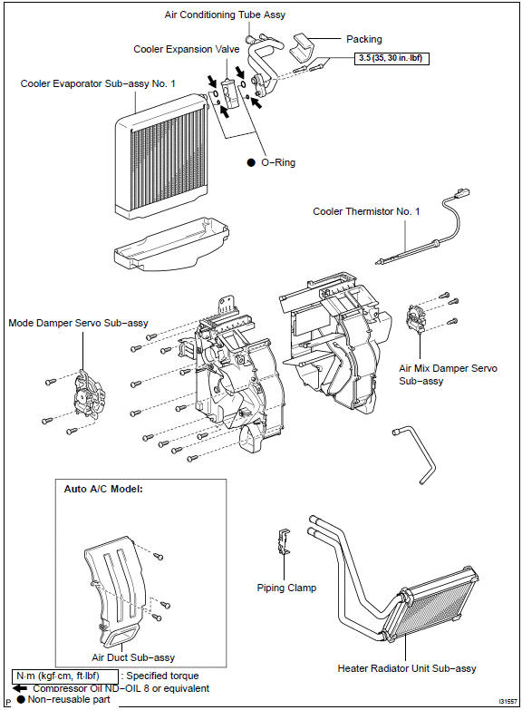
25. REMOVE AIR CONDITIONING TUBE ASSY
a. Remove the packing.
- Using a hexagon wrench 4 mm (0.16 in.), remove the 2 hexagon bolts and air conditioning tube assy.
- Remove the 2 O−rings from the air conditioning tube assy.
26. REMOVE COOLER EXPANSION VALVE
a. Remove the cooler expansion valve from the cooler evaporator sub−assy No. 1.
 Remove cooler expansion valve
- REMOVE COOLER THERMISTOR No.1
- REMOVE COOLER EVAPORATOR SUB−ASSY No.1
a. Auto A/C model: Release the fitting claw, remove the 3 screws and air duct sub−assy.
- Remove the 12 screws and heater case LH.
- Remove the cooler evaporator sub−assy No. 1 from the heater case RH.
d. Remove the 2 O−rings from the cooler evaporator sub− assy No. 1.
29. INSTALL COOLER EVAPORATOR SUB−ASSY No.1
a. Apply compressor oil to the contact surfaces of 2 new O− rings and the cooler expansion valve and install them.
Compressor oil: ND−OIL 8 or equivalent
- Install the cooler evaporator sub−assy No. 1 to the heater case RH.
- Install the heater case LH with the 12 screws.
d. Auto A/C model: Install the air duct sub−assy with the 3 screws.
30. INSTALL COOLER EXPANSION VALVE
a. Install the cooler expansion valve to the cooler evaporator No. 1.
31. INSTALL AIR CONDITIONING TUBE ASSY
- Apply compressor oil to the contact surfaces of 2 new O−
rings and the air conditioning tube assy and install them.
Compressor oil: ND−OIL 8 or equivalent
- Using a hexagon wrench 4 mm (0.16 in.), install the air
conditioner tube assy and 2 hexagon bolts to the cooler
evaporator sub−assy No. 1.
Torque: 3.5 N·m (35 kgf·cm, 30 in.·lbf)
c. Install the packing.
HINT: Securely attach so that the gap in the packing will not be mode.
32. INSTALL AIR CONDITIONING RADIATOR ASSY
- Install the air conditioning radiator assy with the 2 nuts.
Torque: 1.5 N·m (15 kgf·cm, 12 in.·lbf)
- Connect the connector.
 Install air conditioning radiator assy
33. INSTALL DEFROSTER NOZZLE ASSY LOWER
a. Install the defroster nozzle assy lower.
NOTICE: After locating the pin 1. in the illustration, install 2., then 3..
 Install defroster nozzle assy lower
34. INSTALL BLOWER ASSY
a. Install the blower assy with the 2 screws and 2 nuts.
Torque: 1.5 N·m (15 kgf·cm, 12 in.·lbf)
b. Install the 6 clamps, connect the wire harness.
- Install the blower connector holder with the screw and clamp.
- Connect the connectors.
35. INSTALL INSTRUMENT PANEL REINFORCEMENT
a. Install the instrument panel reinforcement with the 7 bolts and 3 caps.
b. Install the 3 earth wires with the 3 nuts.
c. Install the 7 clamps, connect the wire harness.
36. INSTALL STEERING COLUMN ASSY
- Install the steering column assy with the 3 bolts.
- Install the 2 clamps.
c. Install the steering side connector block with the 2 nuts.
Torque: 8.4 N·m (85 kgf·cm, 73 in.·lb
f)
d. Install the driver side junction block with the 3 nuts.
Torque: 8.4 N·m (85 kgf·cm, 73 in.·lbf)

37. INSTALL INSTRUMENT PANEL BRACE SUB−ASSY No.2
a. Install the instrument panel brace sub−assy No. 2 Ωith the 2 nuts and bolt.
b. Install the nut and clamp.
c. Install the earth wire with the bolt.
d. Install the passenger side junction block with the nut and clamp.
Torque: 8.4 N·m (85 kgf·cm, 73 in.·lbf)
38. INSTALL INSTRUMENT FINISH PANEL RETAINER LOWER
a. Install the instrument finish panel retainer lower with the 2 bolts.
 Install instrument finish panel retainer lower
39. INSTALL INSTRUMENT PANEL BRACE SUB−ASSY No.1
- Install the instrument panel brace sub−assy No. 1 Ωith the nut.
- Install the bolt and screw.
Torque: 9.8 N·m (100 kgf·cm, 87 in.·lbf) (Screw)
c. Install the 2 clamps.
d. Install the 2 earth wires with the 2 bolts.
- INSTALL INSTRUMENT PANEL SAFETY PAD SUB−ASSY
- INSTALL COOLER REFRIGERANT SUCTION HOSE No.1
- Lubricate new O−ring with compressor oil and install them
to the hose.
Compressor oil: ND−OIL 8 or equivalent
- Install the cooler refrigerant suction hose No.1 and piping clamp.
HINT: After connection, check the fitting for claw of the piping clamp.
 Install cooler refrigerant suction hose No.1
42. INSTALL COOLER REFRIGERANT LIQUID PIPE A
HINT: Install in the same way as the cooler refrigerant suction hose No. 1.
- ADD COOLANT
3MZ−FE:
1MZ−FE:
2AZ−FE:
- CHARGE REFRIGERANT
SST 07110−58060 (07117−58060, 07117−58070, 07117−58080, 07117−58090, 07117−78050, 07117−88060, 07117−88070, 07117−88080) Specified amount: 550 50 g (19.37 1.76 oz.)
- WARM UP ENGINE
- CHECK FOR ENGINE COOLANT LEAKS
3MZ−FE:
1MZ−FE:
2AZ−FE: - INSPECT LEAKAGE OF REFRIGERANT
Air conditioning system
Refrigerant
Air conditioning system
Refrigerant
Refrigerant line
V (cooler compressor to crankshaft pulley) beltNNo.1
Air conditioner control assembly
Air conditioning panel sub-assy
Air conditioning radiator assy
Air conditioning system
Blower assy
Cooler compressor assy (3MZ−FE)
Cooler compressor assy (1MZ−FE)
Cooler compressor assy (2AZ−FE)
Cooler condenser assy
Toyota Camry XV30 (2002–2006) Service Manual
- Introduction
- Audio & visual system
- Automatic transmission / trans
- Brake
- Clutch
- Communication system
- Cooling
- Cruise control
- Drive shaft / propeller shaft
- Emission control
- Engine control system
- Engine hood/door
- Engine mechanical
- Exhaust
- Exterior/interior trim
- Front suspension
- Fuel
- Heater & air conditioner
- Ignition
- Instrument panel/meter
- Intake
- Lighting
- Lubrication
- Manual transmission/transaxle
- Parking brake
- Power steering
- Rear suspension
- Seat
- Service specifications
- Sliding roof/convertible
- Starting & charging
- Steering column
- Supplemental restraint system
- Theft deterrent & door lock
- Tire & wheel
- Windshield/windowglass/mirror
- Wiper & washer
- Wiring
Categories
