 Toyota Camry XV30 (2002–2006) Service ManualHeater & air conditioner
Cooler compressor assy (3MZ−FE)
Cooler compressor assy (3MZ−FE)
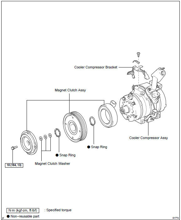
COMPONENTS
REPLACEMENT
HINT: COMPONENTS:
- DISCHARGE REFRIGERANT FROM REFRIGERATION SYSTEM
SST 07110−58060 (07117−58080, 07117−58090, 07117−78050, 07117−88060, 07117−88070, 07117−88080)
- REMOVE V (COOLER COMPRESSOR TO CRANKSHAFT PULLEY) BELT No.1
- REMOVE GENERATOR ASSY
- DISCONNECT COOLER REFRIGERANT DISCHARGE HOSE No.1
- Remove the nut and disconnect the cooler refrigerant discharge hose No.1.
- Remove the O−ring from the cooler refrigerant discharge hose No.1.
NOTICE: Seal the opening of the disconnected parts using vinyl tape to prevent moisture and foreign matter from entering.
 Disconnect cooler refrigerant discharge hose No.1
5. DISCONNECT COOLER REFRIGERANT SUCTION HOSE No.1
- Remove the nut and disconnect the cooler refrigerant suction hose No.1.
- Remove the O−ring from the cooler refrigerant suction hose No.1.
NOTICE: Seal the opening of the disconnected parts using vinyl tape to prevent moisture and foreign matter from entering.
 Disconnect cooler refrigerant suction hose No.1
6. REMOVE COMPRESSOR AND MAGNETIC CLUTCH
- Disconnect the connector and clamp.
- Remove the 2 bolts, nut and cooler compressor bracket.
c. Remove the 3 bolts and compressor and magnetic clutch.
7. REMOVE COOLER COMPRESSOR BRACKET
a. Remove the screw, earth wire and cooler compressor bracket.
 Remove cooler compressor bracket
8. REMOVE MAGNET CLUTCH ASSY
- Remove the bolt and bracket.
- Place the compressor and magnetic clutch in vise.
NOTICE: Do not get the bracket and harness caught in the vise.
- Using SST, hold the magnet clutch hub.
SST 95047−10400
- Remove the bolt, magnet clutch hub and magnet clutch washer.
HINT: There is no set number of magnet clutch washers since they are used for adjusting.
e. Using a snap ring expander, remove the snap ring and magnet clutch rotor.
NOTICE: Do not damage the seal cover of the bearing when removing the snap ring.
f. Disconnect the connector.
g. Using a snap ring expander, remove the snap ring and magnet clutch stator.
9. INSTALL MAGNET CLUTCH ASSY
a. Fit the parts as shown in the illustration and install the magnet clutch stator.
b. Using a snap ring expander, install a new snap ring with the chamfered side facing up.
NOTICE: Do not damage the seal cover of the bearing when removing the snap ring.
c. Connect the connector.
d. Using a snap ring expander, install the magnet clutch rotor and a new snap ring with the chamfered side facing up.
NOTICE:
- Do not expand the snap ring by more than 30.5 mm when installing it.
- Do not damage the seal cover of the bearing when removing the snap ring.
e. Install the magnet clutch washer and magnet clutch hub.
NOTICE: Do not change the combination of the magnet clutch washers used before disassembly.
f. Using SST, hold the magnet clutch hub and install the bolt.
SST 95047−10400 Torque: 18 N·m (184 kgf·cm, 13 ft·lbf)
NOTICE: Make sure that there is no foreign matter or oil on the compressor shaft, bolt, and clutch hub.
10. INSPECT MAGNETIC CLUTCH CLEARANCE
- Set the dial indicator to the magnet clutch hub.
- Connect the battery positive lead to the terminal 3 of magnet
clutch connector and the negative lead to the earth
wire. Turn on and off the magnet clutch and measure the
clearance.
Standard clearance:
0.35 − 0.60 mm (0.014 − 0.024 in.)
If the measured value is out of the standard range, remove the magnet clutch hub and adjust it with magnet clutch washers.
NOTICE: Adjustment shall be performed with 3 or less magnet clutch washers.
c. Remove the compressor and magnetic clutch from the vise.
d. Install the bolt and bracket.

11. INSTALL COOLER COMPRESSOR BRACKET
a. Install the earth wire and cooler compressor bracket with the screw.
 Install cooler compressor bracket
12. INSPECT COMPRESSOR OIL
a. When replacing the compressor and magnetic clutch with new one, after gradually removing the refrigerant gas from the service valve, drain the following amount of oil from the new compressor and magnetic clutch before installation.
Standard: (Oil capacity inside new compressor and magnetic clutch: 120 + 15 cc (4.1 + 0.51 fl.oz.) ) − (Remaining oil amount in the removed compressor and magnetic clutch) = (Oil amount to be removed when replacing)
NOTICE:
- When checking the compressor oil level, observe the precautions on the cooler removal/installation.
- Because compressor oil remains in the pipes of the vehicle, if a new compressor and magnetic clutch is installed without removing some oil inside, the oil amount becomes too much, preventing heat exchange in the refrigerant cycle and causing refrigerant failure.
- If the remaining oil in the removed compressor and magnetic clutch is too small in volume, check for oil leakage.
- Be sure to use ND−OIL8 for compressor oil.
13. TEMPORARILY TIGHTEN COMPRESSOR AND MAGNETIC CLUTCH
a. Temporarily tighten the compressor and magnetic clutch with the 3 bolts.
 Temporarily tighten compressor and magnetic clutch
14. FULLY TIGHTEN COMPRESSOR AND MAGNETIC CLUTCH
a. Tighten the compressor and magnetic clutch with the bolt a. and bolt b..
Torque: 25 N·m (250 kgf·cm, 18 ft·lbf)
b. Install the cooler compressor bracket with the 2 bolts and nut.
Torque:
25 N·m (250 kgf·cm, 18 ft·lbf) (Bolt c.)
25 N·m (250 kgf·cm, 18 ft·lbf) (Nut d.)
18 N·m (184 kgf·cm, 13 ft·lbf) (Bolt e.)
- Tighten the compressor and magnetic clutch with the bolt
f..
Torque: 25 N·m (250 kgf·cm, 18 ft·lbf)
- connect the connector.
15. INSTALL COOLER REFRIGERANT SUCTION HOSE No.1
- Remove the attached vinyl tape from the hose.
- Sufficiently apply compressor oil to the new O−ring and
fit surface of the compressor and magnetic clutch.
Compressor oil: ND−OIL8 or equivalent
- Install a O−ring to the cooler refrigerant suction hose No.1.
d) Install the cooler refrigerant suction hose No.1 to the compressor and magnetic clutch with the nut.
Torque: 9.8 N·m (100 kgf·cm, 87 in.·lbf)
16. INSTALL COOLER REFRIGERANT DISCHARGE HOSE No.1
- Remove the attached vinyl tape from the hose.
- Sufficiently apply compressor oil to the new O−ring and
fit surface of the compressor and magnetic clutch.
Compressor oil: ND−OIL8 or equivalent
- Install a O−ring to the cooler refrigerant discharge hose No.1.
d. Install the cooler refrigerant discharge hose No.1 to the compressor and magnetic clutch with the nut.
Torque: 9.8 N·m (100 kgf·cm, 87 in.·lbf)
- INSTALL GENERATOR ASSY
- INSTALL V (COOLER COMPRESSOR TO CRANKSHAFT PULLEY) BELT No.1
- CHARGE REFRIGERANT
SST 07110−58060 (07117−58060, 07117−58070, 07117−58080, 07117−58090, 07117−78050, 07117−88060, 07117−88070, 07117−88080)
- WARM UP ENGINE
- INSPECT LEAKAGE OF REFRIGERANT
Air conditioning system
Refrigerant
Air conditioning system
Refrigerant
Refrigerant line
V (cooler compressor to crankshaft pulley) beltNNo.1
Air conditioner control assembly
Air conditioning panel sub-assy
Air conditioning radiator assy
Air conditioning system
Blower assy
Cooler compressor assy (3MZ−FE)
Cooler compressor assy (1MZ−FE)
Cooler compressor assy (2AZ−FE)
Cooler condenser assy
Toyota Camry XV30 (2002–2006) Service Manual
- Introduction
- Audio & visual system
- Automatic transmission / trans
- Brake
- Clutch
- Communication system
- Cooling
- Cruise control
- Drive shaft / propeller shaft
- Emission control
- Engine control system
- Engine hood/door
- Engine mechanical
- Exhaust
- Exterior/interior trim
- Front suspension
- Fuel
- Heater & air conditioner
- Ignition
- Instrument panel/meter
- Intake
- Lighting
- Lubrication
- Manual transmission/transaxle
- Parking brake
- Power steering
- Rear suspension
- Seat
- Service specifications
- Sliding roof/convertible
- Starting & charging
- Steering column
- Supplemental restraint system
- Theft deterrent & door lock
- Tire & wheel
- Windshield/windowglass/mirror
- Wiper & washer
- Wiring
Categories
