 Toyota Camry XV30 (2002–2006) Service ManualHeater & air conditioner
Air conditioning system
Air conditioning system
INSPECTION
1. COOLER COMPRESSOR ASSY
- Connect the positive (+) lead from the battery to terminal 3 and the negative (−) lead to the body ground.
- Check that the magnet clutch energized.
If operation is not as specified, replace the magnet clutch assy.
c. Measure resistance between terminals 1 and 2.
Standard resistance: 165 − 205 W at 20 C (68 F)
If resistance is not as specified, replace the cooler compressor assy.
 Cooler compressor assy
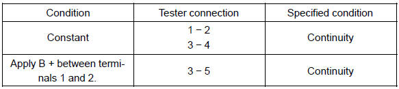
2. MAGNET−CLUTCH RELAY
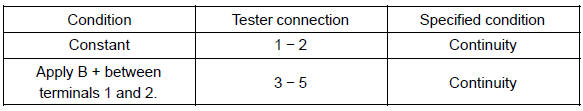
If continuity is not as specified, replace the magnet−clutch relay.
 Magnet-clutch relay
3. AIRMIX DAMPER SERVO SUB−ASSY
a. Inspect servomotor operation.
- Connect the positive (+) lead from the battery to terminal 4 and negative (−) lead to terminal 5, then check that the arm turns to ”COLD” side smoothly.
- Connect the positive (+) lead from the battery to terminal 5 and negative (−) lead to terminal 4, then check that the arm turns to ”HOT” side smoothly.
If operations are not as specified, replace the air mix servomotor.
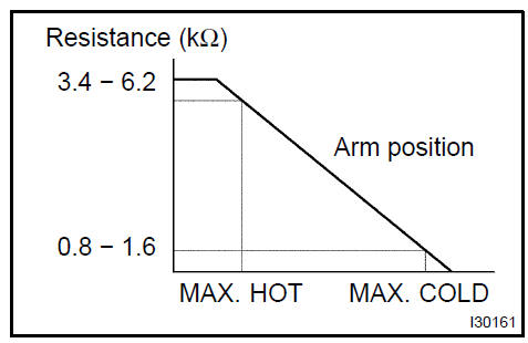
b. Inspect position sensor resistance.
Measure resistance between terminals at servomotor arm each position as shown in the chart.
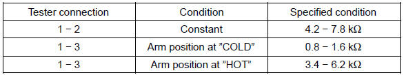
If resistance is not as specified, replace the servomotor.
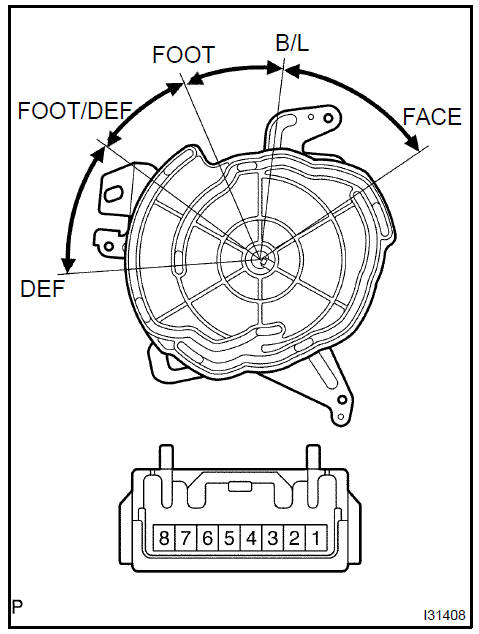
4. MODE DAMPER SERVO SUB−ASSY
a. Inspect servomotor operation.
- Connect the positive (+) lead from the battery to terminal 7 and the negative (−) lead to terminal 8.
- Connect the negative (−) lead from the battery to each terminal as shown in the chart, and check that the shaft rotates at each position, as shown in the illustration.
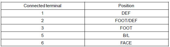
If operation is not as specified, replace the servomoto
 Mode damper servo sub-assy
5. RECIRCULATION DAMPER SERVO SUB−ASSY
a. Inspect servomotor operation.
- Connect the positive (+) lead from the battery to terminal 5 and negative (−) lead to terminal 1, then check that the arm turns to ”REC” side smoothly.
- Connect the positive (+) lead from the battery to terminal 5 and negative (−) lead to terminal 2, then check that the arm turns to ”FRS” side smoothly.
If operations are not as specified, replace the mode damper servomotor.
 Recirculation damper servo sub-assy
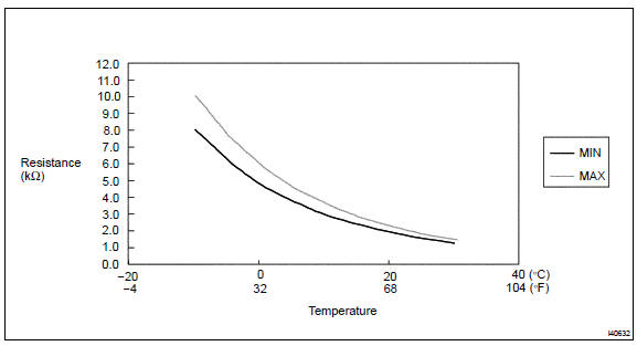
6. COOLER THERMISTOR No.1
- Remove cooler thermistor No.1.
- Check resistance between terminals 1 and 2 of cooler thermistor No.1 at each temperature, as shown in the chart.
Standard:
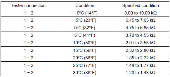
NOTICE: Even slightly touching the sensor may change the resistance value.Be sure to hold the connector of the sensor.
HINT: As the temperature increases, the resistance decreases (see the chart below).
7. BLOWER W/FAN MOTOR SUB−ASSY
a. Connect the positive (+) lead from the battery to terminal 2 and negative (−) to terminal 1, then check that the motor operation smoothly.
If operation is not as specified, replace the blower motor.
 Blower w/fan motor sub-assy
8. BLOWER RESISTOR
a. Measure resistance between terminals, as shown in the chart below.
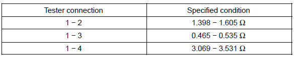
If resistance is not as specified, replace the blower resistor.
 Blower resistor
9. HEATER BLOWER MOTOR RELAY ASSY
If continuity is not as specified, replace the heater blower motor relay
 Heater blower motor relay assy
Air conditioning system
Refrigerant
Air conditioning system
Refrigerant
Refrigerant line
V (cooler compressor to crankshaft pulley) beltNNo.1
Air conditioner control assembly
Air conditioning panel sub-assy
Air conditioning radiator assy
Air conditioning system
Blower assy
Cooler compressor assy (3MZ−FE)
Cooler compressor assy (1MZ−FE)
Cooler compressor assy (2AZ−FE)
Cooler condenser assy
Toyota Camry XV30 (2002–2006) Service Manual
- Introduction
- Audio & visual system
- Automatic transmission / trans
- Brake
- Clutch
- Communication system
- Cooling
- Cruise control
- Drive shaft / propeller shaft
- Emission control
- Engine control system
- Engine hood/door
- Engine mechanical
- Exhaust
- Exterior/interior trim
- Front suspension
- Fuel
- Heater & air conditioner
- Ignition
- Instrument panel/meter
- Intake
- Lighting
- Lubrication
- Manual transmission/transaxle
- Parking brake
- Power steering
- Rear suspension
- Seat
- Service specifications
- Sliding roof/convertible
- Starting & charging
- Steering column
- Supplemental restraint system
- Theft deterrent & door lock
- Tire & wheel
- Windshield/windowglass/mirror
- Wiper & washer
- Wiring
Categories
