 Toyota Camry XV30 (2002–2006) Service ManualManual transmission/transaxle
Input shaft assy (E351)
Input shaft assy (E351)
OVERHAUL
1. INSPECT 4TH GEAR THRUST CLEARANCE
a. Using a feeler gauge, measure the 4th gear thrust clearance.
Standard clearance: 0.10 to 0.57 mm (0.0039 to 0.0224 in.)
 Inspect 4th gear thrust clearance
2. INSPECT 3RD GEAR THRUST CLEARANCE
a. Using a dial indicator, measure the 3rd gear thrust clearance.
Standard clearance: 0.10 to 0.35 mm (0.0039 to 0.0138 in.)
 Inspect 3rd gear thrust clearance
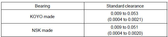
3. INSPECT 4TH GEAR RADIAL CLEARANCE
a. Using a dial indicator, measure the 4th gear radial clearance.
Standard clearance: mm (in.)
If the clearance exceeds the maximum, replace the 4th gear needle roller bearing.
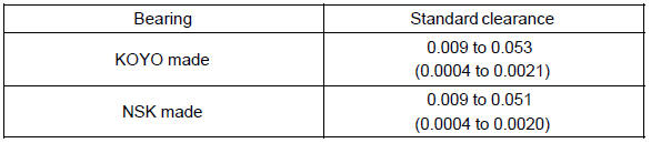
4. INSPECT 3RD GEAR RADIAL CLEARANCE
a. Using a dial indicator, measure the 3rd gear radial clearance.
Standard clearance: mm (in.)
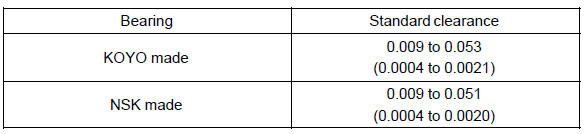
If the clearance exceeds the maximum, replace the 3rd gear needle roller bearing.
 Inspect 3rd gear radial clearance
5. REMOVE 4TH GEAR
- Hold the input shaft assy and soft jaws with a vise.
- Using a 2 screwdrivers and a hammer, remove the input shaft rear bearing shaft snap ring from the input shaft.
NOTICE: Using a waste to prevent the snap ring from being scattered.
c. Using SST and a press, remove the input shaft rear bearing and 4th gear.
SST 09950−00020
NOTICE: Do not tighten SST excessively.
6. REMOVE 4TH GEAR NEEDLE ROLLER BEARING
a. Remove the 4th gear needle roller bearing from the input shaft.
 Remove 4th gear needle roller bearing
7. REMOVE 2ND SYNCHRONIZER OUTER RING
a. Remove the 2nd synchronizer outer ring from the transmission clutch hub No.2.
 Remove 2nd synchronizer outer ring
8. REMOVE 4TH GEAR BEARING SPACER
a. Remove the 4th gear bearing spacer from the transmission clutch hub No.2.
 Remove 4th gear bearing spacer
9. REMOVE 3RD GEAR
a. Using 2 screwdrivers and a hammer, remove the clutch hub No.2 setting shaft snap ring from the input shaft.
NOTICE: Using a waste to prevent the snap ring from being scattered.
b. Using SST and a press, remove the transmission clutch hub No.2 and 3rd gear from the input shaft.
SST 09950−00020
NOTICE: Do not tighten SST excessively.
10. REMOVE 3RD GEAR NEEDLE ROLLER BEARING
a. Remove the 3rd gear needle roller bearing from the input shaft.
 Remove 3rd gear needle roller bearing
11. REMOVE SYNCHRONIZER RING No.3
a. Remove the synchronizer ring No.3 from the 3rd gear.
 Remove synchronizer ring No.3
12. REMOVE TRANSMISSION HUB SLEEVE No.2
a. Remove the transmission hub sleeve No.2, 3 synchromesh shifting keys and 3 synchromesh shifting key springs from the transmission clutch hub No.2.
NOTICE: Using a waste to prevent the shifting key and shifting key spring from being scattered.
 Remove transmission hub sleeve No.2
13. REMOVE INPUT SHAFT FRONT BEARING
a. Using SST and a press, remove the input shaft bearing front (inner race) from the input shaft.
SST 09950−00020
NOTICE: Do not tighten SST excessively.
 Remove input shaft front bearing
14. INSPECT INPUT SHAFT
a. Using V−block and dial indicator, measure the shaft run out.
Maximum run out: 0.03 mm (0.0012 in.)
If the run out exceeds the maximum, replace the input shaft.
 Inspect input shaft
b. Using a micrometer, measure the outer diameter of the input shaft journal surface.
Outer diameter: mm (in.)
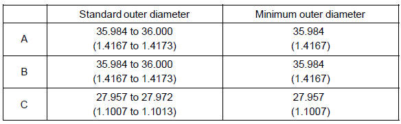
If the outer diameter is less than the minimum, replace the input shaft.
15. INSPECT 4TH GEAR
a. Using a cylinder gauge, measure the inside diameter of the 4th gear.
Inside diameter: mm (in.)
 Inspect 4th gear
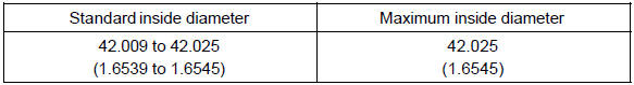
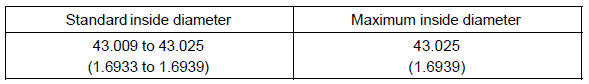
16. INSPECT 3RD GEAR
a. Using a cylinder gauge, measure the inside diameter of the 3rd gear.
Inside diameter: mm (in.)
 Inspect 3rd gear
17. INSPECT 2ND SYNCHRONIZER OUTER RING
a. Coat the 4th gear cone with gear oil. Turn the synchronizer ring No.3 in one direction while pushing it to the 4th gear cone. Check that the ring locks.
b. Using a feeler gauge, measure the clearance between the synchronizer outer ring back and 4th gear spline end.
Standard clearance:
0.75 to 1.65 mm (0.0295 to 0.0650 in.)
If the standard clearance is out of specification, replace the synchronizer ring.
18. INSPECT SYNCHRONIZER RING No.3
a. Coat the 3rd gear cone with gear oil. Turn the synchronizer outer ring in one direction while pushing it to the 3rd gear cone. Check that the ring locks.
b. Using a feeler gauge, measure the clearance between the synchronizer ring No.3 back and 3rd gear spline end.
Standard clearance: 0.65 to 1.75 mm (0.0256 to 0.0689 in.)
If the standard clearance is out of specification, replace the synchronizer ring No.3.
19. INSPECT TRANSMISSION HUB SLEEVE No.2
- Inspect the sliding condition between transmission hub sleeve No.2 and transmission clutch hub No.2.
- Inspect tip of spline gear on the transmission hub sleeve No.2 for wear.
c. Using a vernier calipers, measure the transmission hub sleeve No.3 groove and the thickness of the claw part on gear shift fork No.1, and calculate the clearance.
Standard clearance: 0.11 to 0.69 mm (0.0043 to 0.0272 in.) {A − B}
If the clearance is out of the specification, replace the transmission hub sleeve No.2 and gear shift fork No.2 Ωith the new one.
20. INSTALL INPUT SHAFT FRONT BEARING
a. Using SST and a press, install the input shaft front bearing (inner race).
SST 09608−00071
 Install input shaft front bearing
21. INSTALL TRANSMISSION HUB SLEEVE No.2
- Coat the transmission hub sleeve No.2 Ωith gear oil.
- Install the 3 synchromesh key springs with transmission hub sleeve No.2.
NOTICE: Do not install the transmission clutch hub sleeve No.2 and the transmission clutch hub No.2 incorrect orientation.
c. Using a screwdriver, install the synchromesh shifting key to the input shaft.
 Install transmission hub sleeve No.2
22. INSTALL 3RD GEAR NEEDLE ROLLER BEARING
a. Coat the 3rd gear bearing with gear oil, install it to the input shaft.
 Install 3rd gear needle roller bearing
23. INSTALL 3RD GEAR
a. Coat the 3rd gear with gear oil, install it to the input shaft.
 Install 3rd gear
24. INSTALL SYNCHRONIZER RING No.3
a. Coat the synchronizer ring No.3 with gear oil, install it to the 3rd gear.
 Install synchronizer ring No.3
25. INSTALL TRANSMISSION CLUTCH HUB No.2
a. Using SST and a press, install the transmission clutch hub No.2 to the input shaft.
SST 09316−60011 (09316−00041)
NOTICE:
- Align the claw of clutch hub No.2 Ωith notch of synchronizer ring No.3 and install them.
- Make sure that the 3rd gear should rotate.
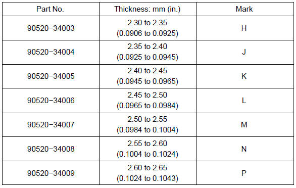
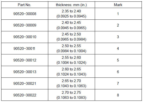
b. Select a snap ring so that clearance between the transmission clutch hub No.2 and the clutch hub No.2 shaft snap ring will be the standard clearance. Using a brass bar and a hammer, install the snap ring.
Standard clearance: 0.1 mm or less (0.0039 or less) Snap ring thickness
26. INSTALL 4TH GEAR BEARING SPACER
a. Coat the 4th gear bearing spacer with gear oil, install it to the input shaft.]
 Install 4th gear bearing spacer
27. INSTALL 2ND SYNCHRONIZER OUTER RING
a. Coat the 2nd synchronizer outer ring with gear oil, install it to the transmission clutch hub No.2.
NOTICE: Align the claw of the clutch hub No.2 Ωith the notch of the 2nd synchronizer outer ring and assemble.
 Install 2nd synchronizer outer ring
28. INSTALL 4TH GEAR NEEDLE ROLLER BEARING
a. Coat the 4th gear needle roller bearing with gear oil, install it to the input shaft.
 Install 4th gear needle roller bearing
29. INSTALL 4TH GEAR
a. Coat the 4th gear with gear oil, install it to the input shaft.
 Install 4th gear
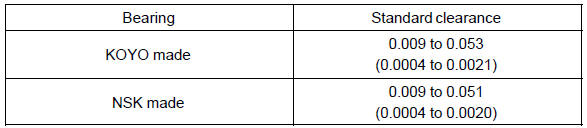
30. INSTALL INPUT SHAFT REAR RADIAL BALL BEARING
a. Using SST and a press, install the input shaft rear radial ball bearing to the input shaft.
NOTICE:
- Make the groove on the bearing face to the rear and install.
- Make sure that the 3rd gear rotates.
SST 09608−06041
b. Select a snap ring so that the clearance between the Input shaft radial ball rear bearing and the input shaft rear bearing snap ring will be the standard clearance. Using a brass bar and a hammer, install the snap ring.
Standard clearance: 0.1 mm or less Snap ring
31. INSPECT 3RD GEAR RADIAL CLEARANCE
a. Using a dial indicator, measure the 3rd gear radial clearance.
Standard clearance: mm (in.)
If the clearance exceeds the maximum, replace the 3rd gear needle roller bearing.
 Inspect 3rd gear radial clearance
32. INSPECT 4TH GEAR RADIAL CLEARANCE
a. Using a dial indicator, measure the 4th gear radial clearance.
Standard clearance: mm (in.)
If the clearance exceeds the maximum, replace the 4th gear needle roller bearing.
 Inspect 4th gear radial clearance
33. INSPECT 3RD GEAR THRUST CLEARANCE
a. Using a dial indicator, measure the 3rd gear thrust clearance.
Standard clearance: 0.10 to 0.35 mm (0.0039 to 0.0138 in.)
 Inspect 3rd gear thrust clearance
34. INSPECT 4TH GEAR THRUST CLEARANCE
a. Using a feeler gauge, measure the 4th gear thrust clearance.
Standard clearance: 0.10 to 0.57 mm (0.0039 to 0.0224 in.)
 Inspect 4th gear thrust clearance
Manual transaxle system
Manual transaxle assy (From July, 2003)
Manual transaxle assy (E351)
Manual transaxle oil
Front differential oil seal
Floor shift shift lever assy
Input shaft assy (E351)
Output shaft assy (E351)
Floor shift cable transmission control shift
Shift & select lever shaft assy (E351)
Differential case assy (E351)
Floor shift cable transmission control select
Toyota Camry XV30 (2002–2006) Service Manual
- Introduction
- Audio & visual system
- Automatic transmission / trans
- Brake
- Clutch
- Communication system
- Cooling
- Cruise control
- Drive shaft / propeller shaft
- Emission control
- Engine control system
- Engine hood/door
- Engine mechanical
- Exhaust
- Exterior/interior trim
- Front suspension
- Fuel
- Heater & air conditioner
- Ignition
- Instrument panel/meter
- Intake
- Lighting
- Lubrication
- Manual transmission/transaxle
- Parking brake
- Power steering
- Rear suspension
- Seat
- Service specifications
- Sliding roof/convertible
- Starting & charging
- Steering column
- Supplemental restraint system
- Theft deterrent & door lock
- Tire & wheel
- Windshield/windowglass/mirror
- Wiper & washer
- Wiring
Categories
