 Toyota Camry XV30 (2002–2006) Service ManualManual transmission/transaxle
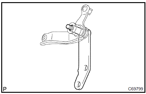
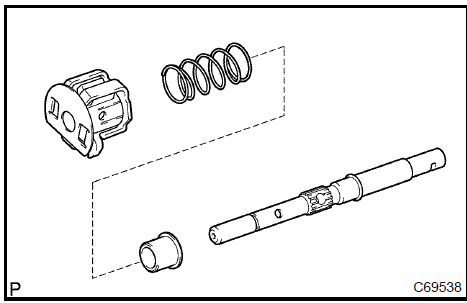
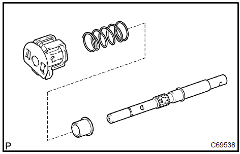
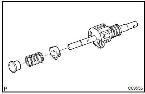
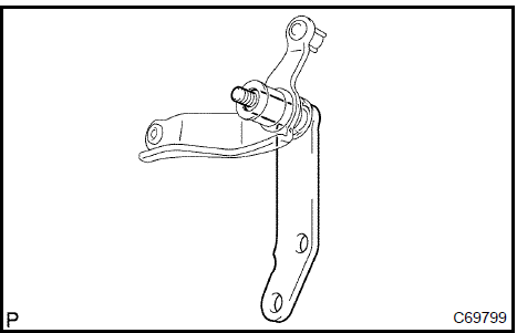
Shift & select lever shaft assy (E351)
Shift & select lever shaft assy (E351)
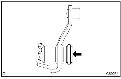
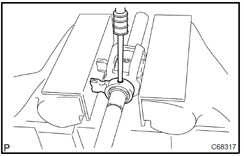
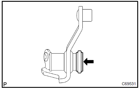
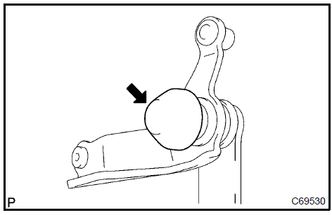
1. REMOVE CONTROL SHIFT LEVER BUSH
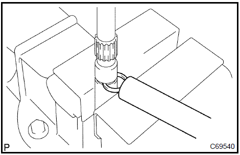
a. Remove the control shift lever bush from the selecting bellcrank No.2.
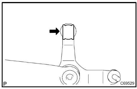 Remove control shift lever bush
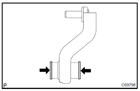
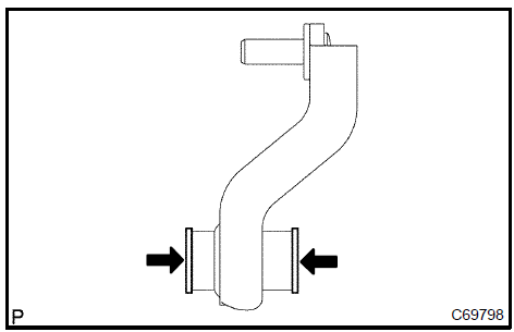
2. REMOVE SELECTING BELLCRANK DUST COVER No.1
a. Remove the selecting bellcrank dust cover No.1 from the selecting bellcrank No.2.
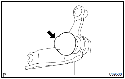 Remove selecting bellcrank dust cover No.1
3. REMOVE SELECTING BELLCRANK SUPPORT SUB−ASSY
a. Remove the nut, washer and selecting bellcrank No.2 plate washer from the selecting bellcrank No.2.
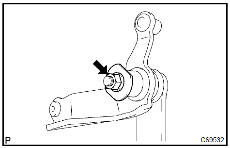
b. Remove the selecting bellcrank support sub−assy from the selecting bell crank No.2.
4. REMOVE SELECTING BELLCRANK DUST COVER No.2
a. Remove the selecting bell crank dust cover No.2 from the selecting bellcrank No.2.
 Remove selecting bellcrank dust cover No.2
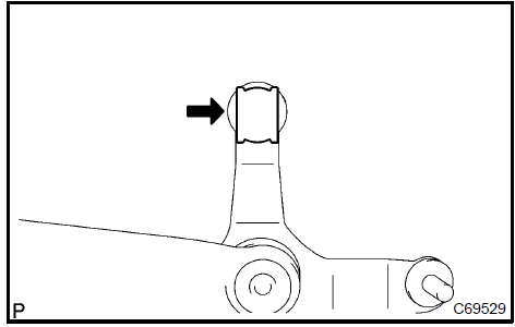
5. REMOVE SELECTING BELLCRANK No.2 BUSH
a. Remove the selecting bellcrank bush from the selecting bellcrank No.2.
 Remove selecting bellcrank No.2 Bush
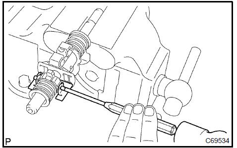
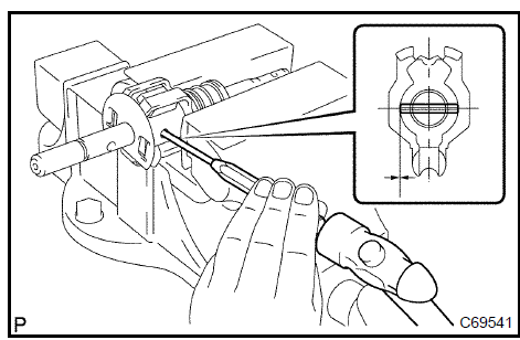
6. REMOVE SHIFT LEVER INNER No.2
a. Hold the shift & select lever on the vise through the soft jaw.
NOTICE: Do not damage the shift & select lever shaft.
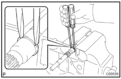
b. Using a pin punch (f 5 mm), remove the shift & select lever inner slotted pin and oil baffle.
NOTICE: Do not damage the shift & select lever shaft.
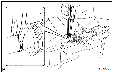
c. Apply the force to the select return spring No.1 and select return spring No.2 then hold it on the vise through the soft jaw.
d. Using 2 screwdrivers and a hammer, remove the select seat snap ring from the shift & select lever shaft.
NOTICE: Do not damage the shift & select lever shaft.
7. REMOVE SELECT SPRING SEAT No.1
a. Using a pin punch (ϕ 5 mm), remove the shift inner lever slotted pin from the shift & select lever shaft.
b. Remove the shift lever assy select return spring No.1 and select spring seat from the shift & select lever shaft.
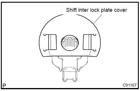
8. REMOVE SHIFT INTER LOCK PLATE COVER
a. Remove the shift inter lock plate cover from the shift inter lock plate.
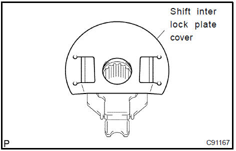 Remove shift inter lock plate cover
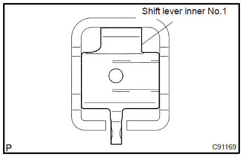
9. REMOVE SHIFT LEVER INNER No.1
a. Remove the shift lever inner No.1 from the shift inter lock plate.
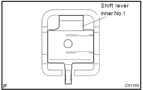 Remove shift lever inner No.1
10. REMOVE SELECT SPRING No.1 SEAT SHAFT SNAP RING
a. Using 2 screwdrivers and a hammer, remove the select spring No.1 seat shaft snap ring.
NOTICE: Do not damage the shaft.
 Remove select spring No.1 Seat shaft snap ring
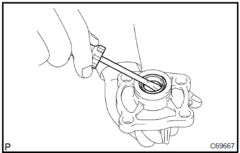
11. REMOVE CONTROL SHAFT COVER OIL SEAL
a. Using a screwdriver, remove the control shaft cover oil seal from the control shaft cover.
 Remove control shaft cover oil seal
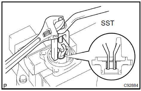
12. REMOVE CONTROL SHAFT COVER BIMETAL FORMED BUSH
a. Using SST, remove the control shaft cover bimetal formed bush from the control shift cover.
SST 09319−60020
 Remove control shaft cover bimetal formed bush
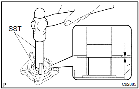
13. INSTALL CONTROL SHAFT COVER BIMETAL FORMED BUSH
a. Using SST and hammer, install a new control shaft cover bimetal formed bush to the control shaft cover.
SST 09950−60010 (09951−00210), 09950−70010 (09951−07100)
Oil seal drive in depth: 0 0.25 mm (0 0.010 in.)
 Install control shaft cover bimetal formed bush
14. INSTALL CONTROL SHAFT COVER OIL SEAL
a. Using SST and hammer, install a new control shaft cover oil seal to the control shaft cover.
SST 09950−60010 (09951−00280), 09950−70010 (09951−07100)
Oil seal drive in depth: 28.5 0.50 mm (1.122 0.020 in.)
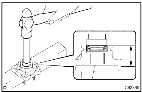 Install control shaft cover oil seal
15. INSTALL SELECT SPRING No.1 SEAT SHAFT SNAP RING
a. Using a brass bar and a hammer, install the select spring No.1 seat shaft snap ring.
 Install select spring No.1 Seat shaft snap ring
16. INSTALL SHIFT LEVER INNER No.1
a. Install the shift lever inner No.1 to the shift inter lock plate.
 Install shift lever inner No.1
17. INSTALL SHIFT INTER LOCK PLATE COVER
a. Install the shift inter lock plate cover to the shift inter lock plate.
 Install shift inter lock plate cover
18. INSTALL SELECT SPRING SEAT No.1
a. Install the select spring seat No.1, select return spring No.1 and shift lever inner assy to the shift & select lever shaft.
 Install select spring seat No.1
- Hold the shift & select lever on the vise through the soft jaw.
- Using a pin punch (f 5 mm), install the shift lever slotted
pin to the shift & select lever shaft.
Clearance: −0.5 − 0.5 mm (− 0.0197 − 0.0197 in.)
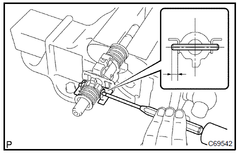
19. INSTALL SHIFT LEVER INNER No.2
- Install shift lever inner No.2, select return spring No.2 and select return spring seat No.2 to the shift & select lever shaft.
- Using a brass bar and a hammer, install the select seat snap ring to the shift & select lever shaft.
 Install shift lever inner No.2
c. Install the transmission oil baffle. Using a pin punch (f 5 mm) and a hammer, install the shift inner lever slotted pin to the shift & select lever shaft.
Clearance: 5.8 to 6.8 mm (0.228 to 0.268 in.)
20. INSTALL SELECTING BELLCRANK No.2 BUSH
a. Coat the 2 selecting bellcrank No.2 bushes with MP grease, install it to the selecting bellcrank No.2.
 Install selecting bellcrank No.2 Bush
21. INSTALL SELECTING BELLCRANK DUST COVER No.2
a. Coat the selecting bellcrank dust cover No.2 Ωith MP grease, install it to the selecting bellcrank No.2.
 Install selecting bellcrank dust cover No.2
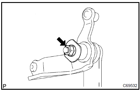
22. INSTALL SELECTING BELLCRANK SUPPORT SUB−ASSY
a. Install the selecting bellcrank support sub−assy to the selecting bellcrank No.2.
b. Install the selecting bellcrank No.2 plate washer, washer and nut.
Torque: 12 N·m (122 kgf·cm, 9 ft·lbf)
23. INSTALL SELECTING BELLCRANK DUST COVER No.1
a. Install the selecting bellcrank dust cover No.1 to the selecting bellcrank No.2.
 Install selecting bellcrank dust cover No.1
24. INSTALL CONTROL SHIFT LEVER BUSH
a. Install the control shift lever bush to the selecting bell crank No.2.
 Install control shift lever bush
Manual transaxle system
Manual transaxle assy (From July, 2003)
Manual transaxle assy (E351)
Manual transaxle oil
Front differential oil seal
Floor shift shift lever assy
Input shaft assy (E351)
Output shaft assy (E351)
Floor shift cable transmission control shift
Shift & select lever shaft assy (E351)
Differential case assy (E351)
Floor shift cable transmission control select
Toyota Camry XV30 (2002–2006) Service Manual
- Introduction
- Audio & visual system
- Automatic transmission / trans
- Brake
- Clutch
- Communication system
- Cooling
- Cruise control
- Drive shaft / propeller shaft
- Emission control
- Engine control system
- Engine hood/door
- Engine mechanical
- Exhaust
- Exterior/interior trim
- Front suspension
- Fuel
- Heater & air conditioner
- Ignition
- Instrument panel/meter
- Intake
- Lighting
- Lubrication
- Manual transmission/transaxle
- Parking brake
- Power steering
- Rear suspension
- Seat
- Service specifications
- Sliding roof/convertible
- Starting & charging
- Steering column
- Supplemental restraint system
- Theft deterrent & door lock
- Tire & wheel
- Windshield/windowglass/mirror
- Wiper & washer
- Wiring
Categories
