 Toyota Camry XV30 (2002–2006) Service ManualFuel
Fuel injector assy (1MZ−FE/3MZ−FE)
Fuel injector assy (1MZ−FE/3MZ−FE)
COMPONENTS
REPLACEMENT
- DISCHARGE FUEL SYSTEM PRESSURE
- DRAIN ENGINE COOLANT
- REMOVE FRONT SUSPENSION UPPER BRACE CENTER
a. Remove the 2 nuts and upper brace.
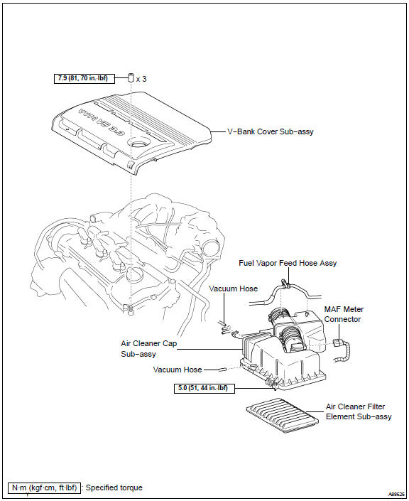
- REMOVE V−BANK COVER SUB−ASSY
- REMOVE AIR CLEANER CAP SUB−ASSY
- Disconnect the MAF meter connector.
- Disconnect the 4 vacuum hoses.
- Disconnect the ventilation hose No. 2.
- Remove the fuel vapor feed hose from the 2 hose clamps.
- Loosen the 2 air cleaner cap bolts.
- Loosen the air cleaner hose clamp bolt, and remove the air cleaner cap.
- Remove the air cleaner filter element.
 Remove air cleaner cap sub-assy
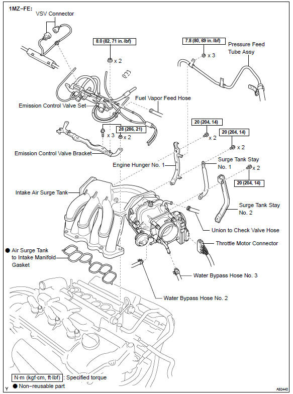
6. REMOVE EMISSION CONTROL VALVE SET (1MZ−FE ENGINE TYPE)
- Disconnect the 3 VSV connectors.
- Remove the wire harness clamp.
- Disconnect the fuel vapor feed hose No. 1.
- Disconnect the fuel vapor feed hose No. 2.
- Disconnect the 3 vacuum hoses.
- Remove the clamp.
- Remove the 2 nuts, and then remove the emission control valve set.
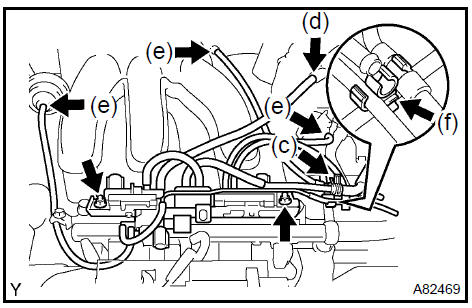
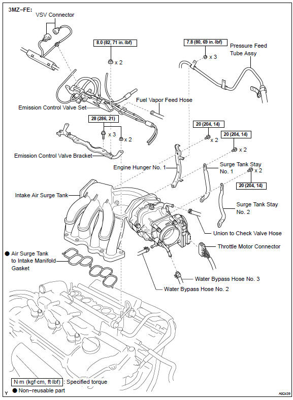
7. REMOVE EMISSION CONTROL VALVE SET (3MZ−FE ENGINE TYPE)
- Disconnect the 2 VSV connectors.
- Remove the wire harness clamp.
- Disconnect the fuel vapor feed hose No. 1.
- Disconnect the fuel vapor feed hose No. 2.
- Disconnect the 2 vacuum hoses.
- Remove the clamp.
- Remove the 2 nuts and the emission control valve set.
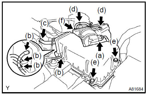
8. REMOVE INTAKE AIR SURGE TANK
- Disconnect the throttle motor connector.
- Disconnect the water bypass hose No. 3.
- Disconnect the water bypass hose No. 2.
- Disconnect the union to check valve hose.
e. Disconnect the ventilation hose.
f. Remove the 3 nuts and separate the pressure feed tube.
- Remove the 2 bolts and engine hunger No. 1.
- Remove the 2 bolts and surge tank stay No. 1.
- Remove the 2 bolts and surge tank stay No. 2.
- Using a socket hexagon wrench 8, remove the 4 bolts.
- Remove the 2 nuts, emission control valve bracket and intake air surge tank.
- Remove the gasket from the intake air surge tank.
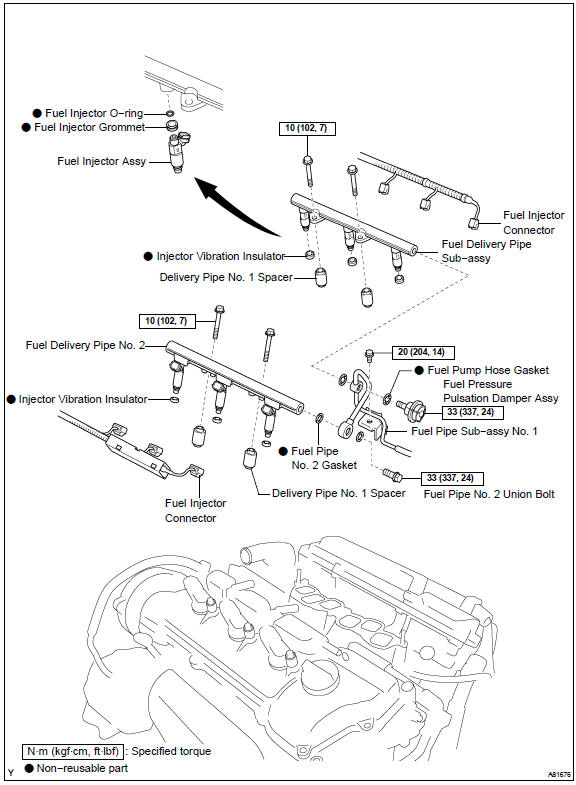
9. SEPARATE FUEL PIPE SUB−ASSY No.1
- Remove the bolt and disconnect the fuel pipe No. 1.
- Remove the fuel pressure pulsation damper and 2 gaskets.
- Remove the fuel pipe No. 2 union bolt and 2 gaskets.
 Separate fuel pipe sub-assy No.1
10. REMOVE FUEL INJECTOR ASSY
a. Disconnect the 6 fuel injector connectors.
b. Remove the 4 bolts and 2 fuel delivery pipes together with the 6 fuel injectors.
NOTICE: Be careful not to drop the fuel injectors when removing the fuel delivery pipe.
c. Remove the 4 delivery pipe No. 1 spacers ( 1) and 6 insulators ( 2) from the intake manifold.
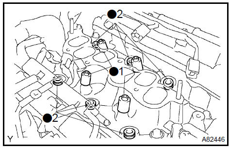
d. Pull out the fuel injector from the fuel delivery pipe.
11. INSTALL FUEL INJECTOR ASSY
- Install a new grommet to each injector.
- Apply a light coat of grease or gasoline to a new O−ring, and install it to each injector.
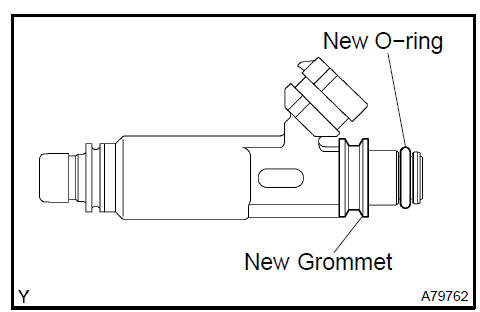
- Apply a light coat of grease or gasoline on the place where the fuel delivery pipe contacts the O−ring.
- Push the fuel injector while twisting it back and forth to install it in the fuel delivery pipe.
NOTICE:
- Be careful not to twist the O−ring.
- After installing the fuel injector, check that it turns smoothly. If not, reinstall it with a new O−ring.
- Install 6 new insulators and the 4 delivery pipe No. 1 spacers to the intake manifold.
- Place the 2 fuel delivery pipes and the 6 fuel injectors together on the intake manifold.
NOTICE: Be careful not to drop the fuel injectors when installing the fuel delivery pipe.
g. Temporarily install the 4 bolts which are used to attach the fuel delivery pipe to the intake manifold.
NOTICE: After installing the fuel injector, check that it turns smoothly.
If not, reinstall it with a new O−ring.
- Tighten the 4 bolts.
Torque: 10 N·m (102 kgf·cm, 7 ft·lbf)
- Connect the 6 fuel injector connectors.
12. INSTALL FUEL PIPE SUB−ASSY No.1
- Install 2 new gaskets and the fuel pipe No. 2 union bolt.
Torque: 33 N·m (337 kgf·cm, 24 ft·lbf)
- Install 2 new gaskets and the fuel pressure pulsation damper.
Torque: 33 N·m (337 kgf·cm, 24 ft·lbf)
- Install the fuel pipe No. 1 Ωith the bolt.
Torque: 20 N·m (204 kgf·cm, 14 ft·lbf)
13. INSTALL INTAKE AIR SURGE TANK
- Install a new gasket to the intake air surge tank.
- Install the intake air surge tank and emission control valve bracket
with the 2 nuts.
Torque: 28 N·m (286 kgf·cm, 21 ft·lbf)
- Using a socket hexagon wrench 8, tighten the 4 bolts.
Torque: 28 N·m (286 kgf·cm, 21 ft·lbf)
- Install the surge tank stay No. 2 Ωith the 2 bolts.
Torque: 20 N·m (204 kgf·cm, 14 ft·lbf)
- Install the surge tank stay No. 1 Ωith the 2 bolts.
Torque: 20 N·m (204 kgf·cm, 14 ft·lbf)
- Install the engine hunger No. 1 Ωith the 2 bolts.
Torque: 20 N·m (204 kgf·cm, 14 ft·lbf)
- Install the pressure feed tube with the 3 nuts.
Torque: 7.8 N·m (80 kgf·cm, 69 in.·lbf)
- Connect the ventilation hose.
- Connect the union to check valve hose.
- Connect the water bypass hose No. 2.
- Connect the water bypass hose No. 3.
- Connect the throttle motor connector.
- INSTALL EMISSION CONTROL VALVE SET (1MZ−FE ENGINE TYPE) Torque: 8.0 N·m (82 kgf·cm, 71 in.·lbf)
- INSTALL EMISSION CONTROL VALVE SET (3MZ−FE ENGINE TYPE) Torque: 8.0 N·m (82 kgf·cm, 71 in.·lbf)
- INSTALL AIR CLEANER CAP SUB−ASSY Torque: 5.0 N·m (51 kgf·cm, 44 in.·lbf)
- CHECK CONNECTION OF VACUUM HOSE
- ADD ENGINE COOLANT
- CHECK FOR ENGINE COOLANT LEAKS
- CHECK FOR FUEL LEAKS
- INSTALL V−BANK COVER SUB−ASSY
- INSTALL FRONT SUSPENSION UPPER BRACE CENTER
a. Install the upper brace with the 2 nuts.
Torque: 80 N·m (815 kgf·cm, 59 ft·lbf)
Fuel system (2AZ−FE)(From July, 2003)
Fuel injector assy (2AZ−FE)(From July, 2003)
Fuel pump assy (2AZ−FE)(From July, 2003)
Fuel tank assy (2AZ−FE)(From July, 2003)
Fuel system (1MZ−FE/3MZ−FE)
Fuel injector assy (1MZ−FE/3MZ−FE)
Fuel system (2AZ−FE)(From July, 2003)
Fuel pump assy (1MZ−FE/3MZ−FE)
Fuel tank assy (1MZ−FE/3MZ−FE)
Fuel system (2AZ−FE)(From July, 2003)
Fuel injector assy (2AZ−FE)(From July, 2003)
Toyota Camry XV30 (2002–2006) Service Manual
- Introduction
- Audio & visual system
- Automatic transmission / trans
- Brake
- Clutch
- Communication system
- Cooling
- Cruise control
- Drive shaft / propeller shaft
- Emission control
- Engine control system
- Engine hood/door
- Engine mechanical
- Exhaust
- Exterior/interior trim
- Front suspension
- Fuel
- Heater & air conditioner
- Ignition
- Instrument panel/meter
- Intake
- Lighting
- Lubrication
- Manual transmission/transaxle
- Parking brake
- Power steering
- Rear suspension
- Seat
- Service specifications
- Sliding roof/convertible
- Starting & charging
- Steering column
- Supplemental restraint system
- Theft deterrent & door lock
- Tire & wheel
- Windshield/windowglass/mirror
- Wiper & washer
- Wiring
Categories
