 Toyota Camry XV30 (2002–2006) Service ManualFuel
Fuel system (1MZ−FE/3MZ−FE)
Fuel system (1MZ−FE/3MZ−FE)
PRECAUTION
1. PRECAUTION
- Before working on the fuel system, disconnect the negative (−) terminal cable from the battery.
- Do not smoke or be near an open flame when working on the fuel system.
- Keep gasoline away from rubber or leather parts.
2. DISCHARGE FUEL SYSTEM PRESSURE
CAUTION:
- Do not disconnect any part of the fuel system until you have discharged the fuel system pressure.
- Even after discharging the fuel pressure, place a shop rag over fittings as you separate them to reduce risk of fuel spray on yourself or in the engine compartment.
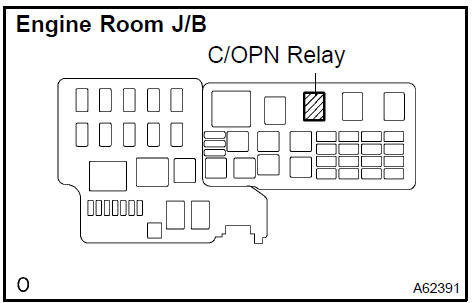
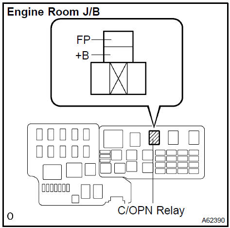
- Remove the C/OPN relay from the engine room J/B.
- Start the engine. After the engine has stopped, turn the ignition switch OFF.
HINT: There is a case that DTC P0171 (system to lean) is output.
- Check that the engine does not start.
- Remove the fuel tank cap, and allow the air out of the fuel tank.
- Disconnect the negative (−) terminal cable from the battery.
- Reinstall the C/OPN relay.
3. FUEL SYSTEM
a. When disconnecting the high fuel pressure line, a large amount of gasoline will spill out, so observe these procedures.
- Try to prevent gasoline from spilling out.
- Disconnect the fuel pump tube.
- Drain the fuel remaining inside the fuel pump tube.
- To protect the disconnected fuel pump tube from damage and contamination, cover it with a vinyl bag.
- Put a container under the connection.
b. Observe the following precautions when removing and installing the fuel injectors.
- Never reuse O−rings.
- When installing a new O−ring on the injector, be careful not to damage it.
- Coat new O−rings with grease or gasoline before installing. Never use engine oil, gear oil or brake oil.
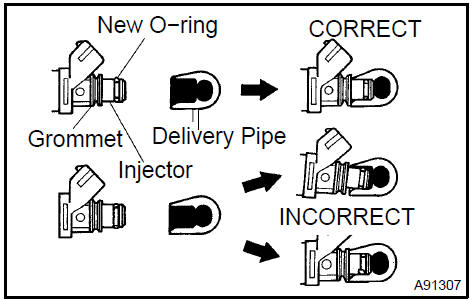
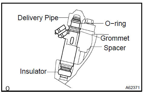
c. Install the injector to the delivery pipe and cylinder head, as shown in the illustration. Before installing the injector, be sure to apply grease or gasoline on the place where the delivery pipe contacts the O−ring of the injector.
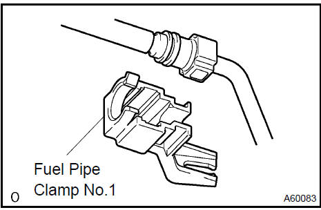
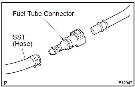
d. Observe these precautions when disconnecting the fuel tube connectors.
- Remove the fuel pipe clamp from the connector.
- Check for dirt or mud on the pipe and around the connector before disconnection. Clean if necessary.
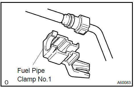
3. Disconnect the connector from the hose while pinching part A with your fingers, as shown in the illustration.
-
If the connector and the pipe are stuck, pinch the fuel pipe, push and pull the connector to disconnect it and pull it out. Do not use any tools.
-
If dirt or any other substance is found on the sealing surface that might interfere with the seal, clean the area thoroughly before assembly.
6. To protect the disconnected pipe and connector from damage and contamination, cover it with a vinyl bag.
e Observe these precautions when connecting the fuel tube connector.
- Check that there is no damage or contamination in the connected part of the pipe.
- Align the axis of the connector with the axis of the pipe. Push the pipe into the connector until the connector makes a ”click” sound. If the connection is tight, apply little amount of fresh engine oil on the tip of the pipe.
- After having finished the connection, check if the pipe and the connector are securely connected by trying to pull them apart.
- Install the fuel pipe clamp to the connector.
- Check if there is any fuel leakage.
4. CHECK FOR FUEL LEAKS
a. Check that there are no fuel leaks after doing maintenance anywhere on the fuel system
ON−VEHICLE INSPECTION
1. CHECK FUEL PUMP OPERATION AND FUEL LEAKS
a. When using the hand−held tester: Check fuel pump operation.
- Connect the hand−held tester to the DLC3.
- Turn the ignition switch ON and push the hand−held tester main switch ON.
NOTICE: Do not start the engine.
- Select the ACTIVE TEST mode on the hand−held tester.
- If you need help to select active test on the hand− held tester, refer to the hand−held tester is instruction manual.
- Turn the ignition switch OFF.
- Disconnect the hand−held tester from the DLC3.
b. When not using the hand−held tester: Check fuel pump operation.
- Remove the C/OPN relay from the engine room J/B.
- Using a service wire, connect terminals FP and +B of the engine room J/B.
NOTICE: Pay close attention to the terminal connecting position to avoid a malfunction.
3. Turn the ignition switch ON, and check that the fuel pump operates.
NOTICE: Do not start the engine.
- Check that there are no fuel leaks after doing maintenance anywhere on the fuel system.
- Turn the ignition switch OFF.
- Remove the servive wire from the engine room J/B.
- Install the C/OPN relay to the engine room J/
2. CHECK FUEL PRESSURE
- Check that the battery positive voltage is above 12 V.
- Disconnect the negative (−) terminal cable from the battery.
- Purchase a new fuel tube and take out the fuel tube connector
from its pipe.
Fuel tube: Part No. 23801−20190
d. Remove the fuel pipe clamp from the fuel tube connector.
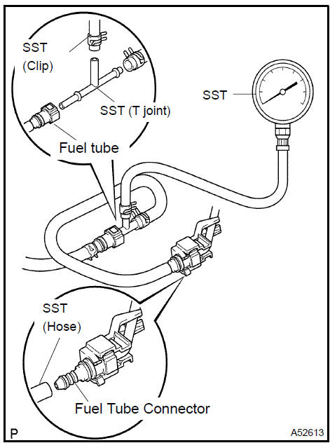
e. Disconnect the fuel tube connector from the fuel pipe by pinching part A with your fingers, as shown in the illustration.
CAUTION:
- Always read the precautions before disconnecting the fuel tube connector (quick type).
- The fuel pipe line may spray fuel as a result of retained pressure that remains in it. Do not allow fuel to be sprayed in the engine compartment.
- Install SST (pressure gauge) and fuel tube connecter using
SST as shown in the illustration.
SST 09268−41047 (90467−13001, 95336−08070), 09268−45014 (09268−41200, 09268−41220, 09268−41250)
- Wipe off any gasoline.
- Reconnect the negative (−) battery cable.
- When using hand−held tester: Operate the fuel pump (see step 1 a.).
- When not using hand−held tester: Operate the fuel pump (see step 1 b.).
- Measure the fuel pressure.
Fuel pressure: 304 to 343 kPa (3.1 to 3.5 kgf/cm2, 44 to 50 ps
i)
If the pressure is high, replace the fuel pressure regulator.
If the pressure is low, check the fuel hoses and connections, fuel pump, fuel filter and fuel pressure regulator.
- Start the engine.
- Measure the fuel pressure at idle.
Fuel pressure: 304 to 343 kPa (3.1 to 3.5 kgf/cm2, 44 to 50 psi)
- Stop the engine.
o. Check that the fuel pressure remains as specified for 5 minutes after the engine has stopped.
Fuel pressure: 147 kPa (1.5 kgf/cm2, 21 psi)
If the pressure is not as specified, check the fuel pump, pressure regulator and/or injectors.
- After checking the fuel pressure, disconnect the negative (−) battery cable and carefully remove SST and fuel tube connector to prevent gasoline from spraying.
- Reconnect the fuel inlet tube (fuel tube connector).
CAUTION: Always read the precautions before connecting the fuel tube connector (quick type).
INSPECTION
1. INSPECT FUEL INJECTOR ASSY
a. Check the injector resistance.
1. Measure the resistance between the terminals.
Standard: 13.4 to 14.2 Ω at 20 C (68 F)
If the result is not as specified, replace the injector.
b. Check the injector injection.
CAUTION:
- This test involves high−pressure fuel and electricity.
Take every precaution regarding safe handling of both the fuel and the electricity.
- Perform this test in a safe area, and avoid any sparks or flame.
- Do not smoke.
1. Purchase the new fuel tube and take out the fuel tube connector from its pipe.
Fuel tube: Parts No. 23801−20190
2. Connect SST and the fuel tube connector to the fuel pipe.
CAUTION: Always read the precautions before connecting the fuel tube connector (quick type).
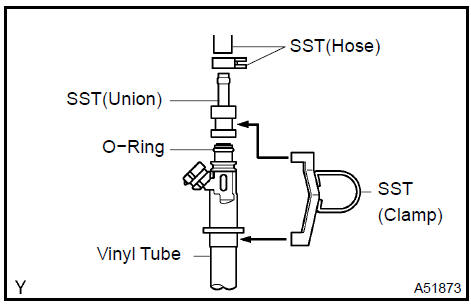
- Install the O−ring to the injector.
- Connect SST (union and hose) to the injector, and hold the injector and the union with SST (clamp)
- Put the injector into a graduated cylinder.
HINT: Install a suitable vinyl tube onto the injector to contain the gasoline spray.
6. Operate the fuel pump
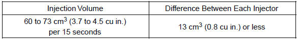
7. Connect SST (wire) to the injector and the battery for 15 seconds, and measure the injection volume with a graduated cylinder. Test each injector 2 or 3 times.
SST 09842−30070
Standard:
NOTICE: Always turn on and off the voltage on the battery side, not the fuel pump side.
If the injection volume is not as specified, replace the injector.
c. Check fuel leakage.
1. In the condition above, disconnect the test probes of SST (wire) from the battery and check the fuel leakage from the injector.
Fuel drop: 1 drop or less per 12 minutes
2. INSPECT FUEL PUMP
a. Check the fuel pump resistance.
1. Measure the resistance between the terminals.
Standard: 0.2 to 3.0 W at 20 C (68 F)
b. Check fuel pump operation.
1. Apply battery voltage to both the terminals. Check that the pump operates.
NOTICE:
- These tests must be done within 10 seconds to prevent the coil from burning out.
- Keep fuel pump as far away from the battery as possible.
- Always turn on and off the voltage on the battery side, not the fuel pump side.
 Inspect fuel pump
Fuel system (2AZ−FE)(From July, 2003)
Fuel injector assy (2AZ−FE)(From July, 2003)
Fuel pump assy (2AZ−FE)(From July, 2003)
Fuel tank assy (2AZ−FE)(From July, 2003)
Fuel system (1MZ−FE/3MZ−FE)
Fuel injector assy (1MZ−FE/3MZ−FE)
Fuel system (2AZ−FE)(From July, 2003)
Fuel pump assy (1MZ−FE/3MZ−FE)
Fuel tank assy (1MZ−FE/3MZ−FE)
Fuel system (2AZ−FE)(From July, 2003)
Fuel injector assy (2AZ−FE)(From July, 2003)
Toyota Camry XV30 (2002–2006) Service Manual
- Introduction
- Audio & visual system
- Automatic transmission / trans
- Brake
- Clutch
- Communication system
- Cooling
- Cruise control
- Drive shaft / propeller shaft
- Emission control
- Engine control system
- Engine hood/door
- Engine mechanical
- Exhaust
- Exterior/interior trim
- Front suspension
- Fuel
- Heater & air conditioner
- Ignition
- Instrument panel/meter
- Intake
- Lighting
- Lubrication
- Manual transmission/transaxle
- Parking brake
- Power steering
- Rear suspension
- Seat
- Service specifications
- Sliding roof/convertible
- Starting & charging
- Steering column
- Supplemental restraint system
- Theft deterrent & door lock
- Tire & wheel
- Windshield/windowglass/mirror
- Wiper & washer
- Wiring
Categories
