 Toyota Camry XV30 (2002–2006) Service ManualIntroduction » How to troubleshoot ecu controlled
systems
Toyota Camry XV30 (2002–2006) Service ManualIntroduction » How to troubleshoot ecu controlled
systems
Electronic circuit inspection procedure
Electronic circuit inspection procedure
1. BASIC INSPECTION
a. RESISTANCE MEASURING CONDITION OF ELECTRONIC PARTS
1. Unless stated, all resistance is measured at an ambient temperature of 20 C (68 F). Resistances measured may be outside the specifications if measured at high temperatures, i.e. immediately after the vehicle has been running. Measurements should be made after the engine has cooled down.
b. HANDLING CONNECTORS
- When disconnecting a connector, first squeeze the mating halves tightly together to release the lock, then press the lock claw and separate the connector.
- When disconnecting a connector, do not pull on the harnesses. Grasp the connector directly and separate it.
- Before connecting the connector, check that there are no deformed, damaged, loose or missing terminals.
- When connecting a connector, press firmly until you hear the lock close with a ”click” sound.
- If checking the connector with a TOYOTA electrical tester, check it from the backside (harness side) of the connector using a mini test lead.
NOTICE:
- As a waterproof connector cannot be checked from the backside, check by connecting a sub−harness.
- Do not damage the terminals by moving the inserted tester needle.
Handling connectors
c. CHECKING CONNECTORS
- Checking when the connector is connected: Squeeze the connector together to confirm that it is fully inserted and locked.
- Checking when the connector is disconnected: Check by pulling the wire harness lightly from the backside of the connector. Look for unlatched terminals, missing terminals, loose crimps or broken conductor wires.
- Check visually for corrosion, metallic or foreign objects and water; and bent, rusted, overheated, contaminated, and deformed terminals.
NOTICE: When testing a gold−plated female terminal, always use a gold−plated male terminal.
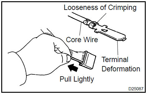
Checking connectors
3. Checking the contact pressure of the terminal: Prepare a spare male terminal. Insert it into a female terminal, and check for good tension when inserting and after full engagement.
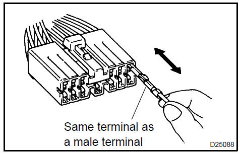
Checking connectors
d. REPAIR METHOD OF CONNECTOR TERMINAL
- If there is any dirt on the terminal, clean the contact point using an air gun or shop rag. Never polish the contact point using a sandpaper as the platings may come off.
- If there is abnormal contact pressure, replace the female terminal. If the male terminal is gold−plated (gold color), use a gold−plated female terminal; if it is silver−plated (silver color), use a silver−plated female terminal.
- Damaged, deformed, or corroded terminals should be replaced. If the terminal will not lock into the housing, the housing may have to be replaced.
Repair method of connector terminal
e. HANDLING OF WIRE HARNESS
- If removing a wire harness, check the wiring and clamping before proceeding so that it can be restored in the same way.
- Never twist, pull or slacken the wire harness more than necessary.
- Never make the wire harness come into contact with a high temperature part, rotating, moving, vibrating or sharp−edged parts. Avoid panel edges, screw tips and similar sharp items.
- When installing parts, never pinch the wire harness.
- Never cut or break the cover of the wire harness. If it is cut or broken, replace it or securely repair it with vinyl tape.
Handling of wire harness
2. CHECK OPEN CIRCUIT
a. For an open circuit in the wire harness in Fig. 1, perform a resistance check (step b) or a voltage check (step c).
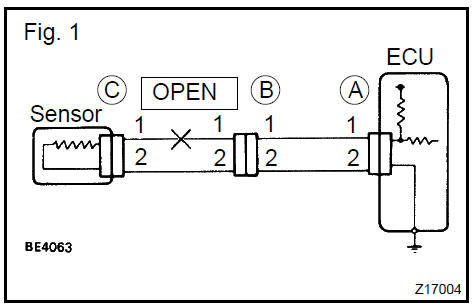
For an open circuit in the wire harness
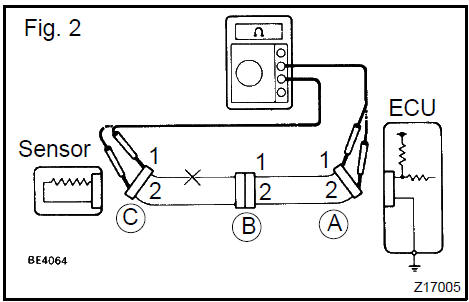
b. Check the resistance.
1. Disconnect connectors A and C and measure the resistance between them.
Resistance: Below 1

HINT: Measure the resistance while lightly shaking the wire harness vertically and horizontally.
Fig. 2:
Between terminal 1 of connector A and terminal 1
of connector C " 10 k or higher
Between terminal 2 of connector A and terminal 2
of connector C " Below 1
If your results match the examples above, an open circuit exists between terminal 1 of connector A and terminal 1 of connector C.
Disconnect connectors A and C and measure the resistance between them
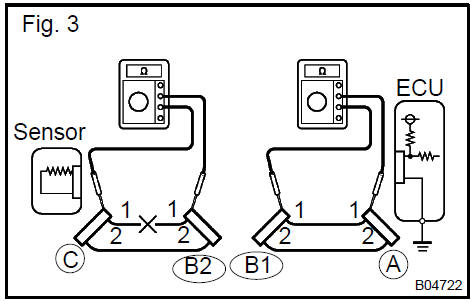
2. Disconnect connector B and measure the resistance between the connectors.
Fig. 3:
Between terminal 1 of connector A and terminal 1
of connector B1 " Below 1
Between terminal 1 of connector B2 and terminal 1
of connector C " 10 k or higher
If your results match the examples above, an open circuit exists between terminal 1 of connector B2 and terminal 1 of connector C.
Disconnect connector B and measure the resistance between the connectors
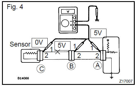
c. Check the voltage.
1. In a circuit in which voltage is applied to the ECU connector terminal, an open circuit can be checked by conducting a voltage check.
Fig. 4: With each connector still connected, measure the voltage between the body ground and terminal 1 of connector A at the ECU 5 V output terminal, terminal 1 of connector B and terminal 1 of connector C, in that order.
2. Example results:
5 V: Between terminal 1 of connector A and body ground
5 V: Between terminal 1 of connector B and body ground
0 V: Between terminal 1 of connector C and body ground
If your results match the examples above, an open circuit exists in the wire harness between terminal 1 of B and terminal 1 of C.
Check the voltage
3. CHECK SHORT CIRCUIT
a. If the wire harness is ground shorted (Fig. 5), locate the section by conducting a resistance check with the body ground (below).
If the wire harness is ground shorted
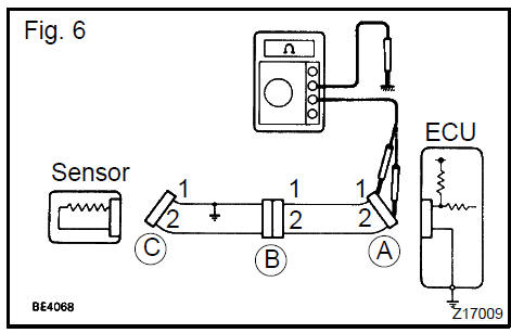
b. Check the resistance with the body ground.
1. Disconnect connectors A and C and measure the resistance between terminals 1 and 2 of connector A and the body ground.
Resistance: 10 k or higher
HINT: Measure the resistance while lightly shaking the wire harness vertically and horizontally.
Fig. 6:
Between terminal 1 of connector A and body
ground " Below 1 
Between terminal 2 of connector A and body
ground " 10 k or higher
If your results match the examples above, a short circuit exists between terminal 1 of connector A and terminal 1 of connector C.
Disconnect connectors A and C and measure the resistance between terminals 1
and 2 of connector A and the body ground
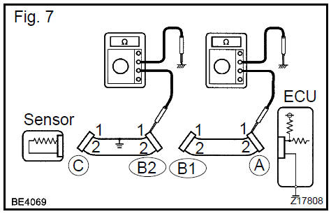
2. Disconnect connector B and measure the resistance between terminal 1 of connector A and the body ground, and terminal 1 of connector B2 and the body ground.
Fig. 7:
Between terminal 1 of connector A and body
ground " 10 k or higher
Between terminal 1 of connector B2 and body
ground " Below 1 
If your results match the examples above, a short circuit exists between terminal 1 of connector B2 and terminal 1 of connector C.
Disconnect connector B and measure the resistance between terminal 1 of
connector A and the body ground, and terminal 1 of connector B2 and the body
ground
4. CHECK AND REPLACE ECU
NOTICE: Start an inspection of the connector from the backside of the connector at the wire harness side with the connector connected to the ECU.
When no measuring condition is specified, perform the inspection with the engine stopped and the ignition switch ON.
Check that the connectors are fully seated. Check for loose, corroded or broken wires.
a First check the ECU ground circuit. If it is faulty, repair it.
If it is normal, the ECU could be faulty. Replace the ECU with a normal functioning one and check if the symptoms occur. If the trouble symptoms stop, replace the ECU.
1. Measure the resistance between the ECU ground terminal and body ground.
Resistance: Below 1 
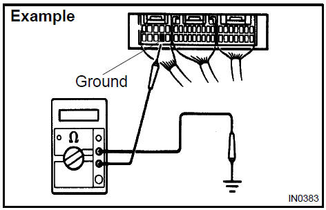
Measure the resistance between the ECU ground terminal and body ground
2. Disconnect the ECU connector. Check the ground terminals (on the ECU side and wire harness side) for evidence of bending, corrosion or foreign material.
Lastly check the contact pressure of the female terminals.
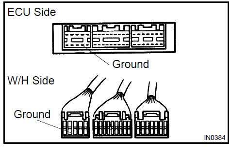
Disconnect the ECU connector
General information
How to proceed with troubleshooting
Customer problem analysis
Symptom confirmation and diagnostic trouble code
Symptom simulation
Diagnostic trouble code chart
Problem symptoms table
Circuit inspection
Electronic circuit inspection procedure
Toyota Camry XV30 (2002–2006) Service Manual
- Introduction
- Audio & visual system
- Automatic transmission / trans
- Brake
- Clutch
- Communication system
- Cooling
- Cruise control
- Drive shaft / propeller shaft
- Emission control
- Engine control system
- Engine hood/door
- Engine mechanical
- Exhaust
- Exterior/interior trim
- Front suspension
- Fuel
- Heater & air conditioner
- Ignition
- Instrument panel/meter
- Intake
- Lighting
- Lubrication
- Manual transmission/transaxle
- Parking brake
- Power steering
- Rear suspension
- Seat
- Service specifications
- Sliding roof/convertible
- Starting & charging
- Steering column
- Supplemental restraint system
- Theft deterrent & door lock
- Tire & wheel
- Windshield/windowglass/mirror
- Wiper & washer
- Wiring
Categories
