 Toyota Camry XV30 (2002–2006) Service ManualSupplemental restraint system
PRECAUTION
CAUTION:
-
The vehicle is equipped with SRS, which consists of a driver airbag, front passenger airbag, side airbag and curtain shield airbag. Failure to carry out service operations in the correct sequence could cause the SRS to unexpectedly deploy during servicing, possibly leading to a serious accident. Further, if a mistake is made in servicing the SRS, it is possible that the SRS may fail to operate when required. Before performing servicing (including removal or installation of parts, inspection or replacement), be sure to read the following items carefully, then follow the correct procedures indicated in the repair manual.
-
Wait at least 90 seconds after the ignition switch is turned to the ”LOCK” position and the negative (−) terminal cable is disconnected from the battery before starting the operation.
(The SRS is equipped with a back−up power source, so that if work is started within 90 seconds after disconnecting the negative (−) terminal cable of the battery, the SRS may be deployed.)
-
Do not expose the horn button assy, front passenger airbag assy, airbag sensor assy center, airbag sensor front, front seat airbag assy, side airbag sensor assy, curtain shield airbag assy, airbag sensor rear or seat position airbag sensor directly to hot air or flames.
-
Be sure to perform the initialization of the occupant classification ECU under the conditions listed below (See page 05−1452). If the initialization is not performed, the SRS may not operate properly.
-
The occupant classification ECU is replaced.
-
Accessories (seatback tray or seat cover, etc.) are installed to the vehicle.
-
The passenger seat is removed from the vehicle.
-
Both the SRS warning light and passenger airbag ON/OFF indicator light (”OFF”) come on.
-
The vehicle is brought to the workshop for repair purpose due to an accident or collision.
NOTICE:
-
Malfunction symptoms of the SRS are difficult to confirm, so DTCs are the most important source of information when troubleshooting. When troubleshooting the SRS, always inspect DTCs before disconnecting the battery.
-
Even in the case of a minor collision when the SRS does not deploy, the horn button assy, front passenger airbag assy, airbag sensor assy center, airbag sensor front, front seat airbag assy, side airbag sensor assy, curtain shield airbag assy, airbag sensor rear and seat position airbag sensor should be inspected.
-
Before repair work, remove the airbag sensor if any kin of shock is likely to occur to the airbag sensor during the operation.
-
Never use SRS parts from another vehicle. When replacing the parts, replace them with new ones.
-
Never disassemble or repair the horn button assy, front passenger airbag assy, airbag sensor assy center, airbag sensor front, front seat airbag assy, side airbag sensor assy, curtain shield airbag assy, airbag sensor rear or seat position airbag sensor in order to reuse it.
-
If the horn button assy, front passenger airbag assy, airbag sensor assy center, airbag sensor front, front seat airbag assy, side airbag sensor assy, curtain shield airbag assy, airbag sensor rear or seat position airbag sensor has been dropped, or if there are any cracks, dents or other defects in the case, bracket or connector, replace it with a new one.
-
Use a volt/ohmmeter with high impedance (10 kW/V minimum) for troubleshooting the electrical circuits.
-
Information labels are attached to the periphery of the SRS components. Follow the instructions in the caution.
-
After work on the SRS is completed, perform the SRS warning light check.
-
When the negative (−) terminal cable is disconnected from the battery, the memory will be cleared. Because of this, be sure to make a record of the contents memorized in each system before starting work. When work is finished, adjust each system as it was before. Never use a back−up power supply from outside the vehicle to avoid erasing the memory in any system.
-
If the vehicle is equipped with a mobile communication system
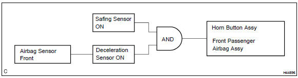
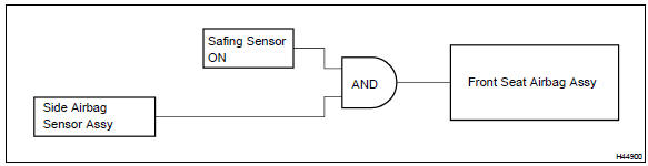
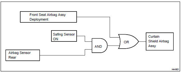
1. DEPLOYMENT CONDITION
a. When the vehicle collides and the shock is greater than the specified value, the SRS is activated automatically.
The airbag sensor assy center includes the safing sensor and deceleration sensor. The safing sensor was designed to be turned on at a smaller deceleration rate than the deceleration sensor.
The deceleration sensor determines whether or not ignition is necessary based on signals from the airbag sensor front. Current flows to the squibs to deploy the SRS when the conditions shown in the illustrations below are met.
2. SRS CONNECTORS
HINT: SRS connectors are located as shown in the following illustration.
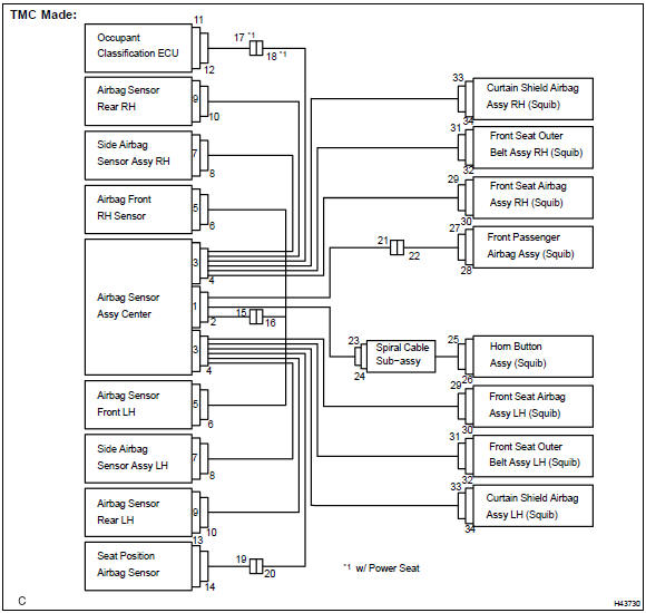
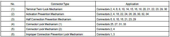
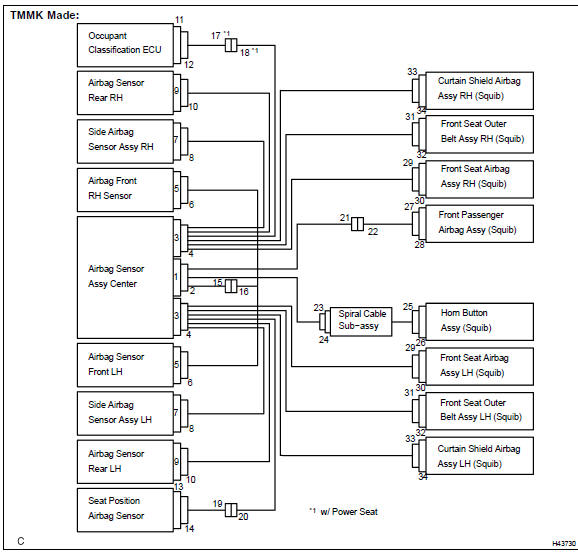
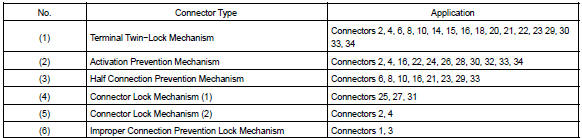
a. All connectors in the SRS are colored yellow to distinguish them from other connectors, except seat position airbag sensor connector and occupant classification ECU connector. Some connectors have special functions, and are specially designed for the SRS. These connectors use durable gold−plated terminals, and are placed in the locations shown on the previous page to ensure high reliability.
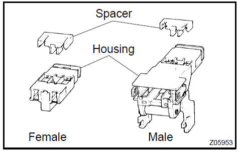
-
Terminal twin−lock mechanism: Each connector has a two−piece component consisting of a housing and a spacer. This design enables the terminal to be locked securely by two locking devices (the retainer and the lance) to prevent terminals from coming out.
-
Activation prevention mechanism: Each connector contains a short spring plate. When the connector is disconnected, the short spring plate automatically connects the positive (+) terminal and the negative (−) terminal of the squib.
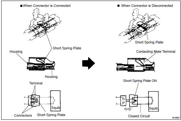
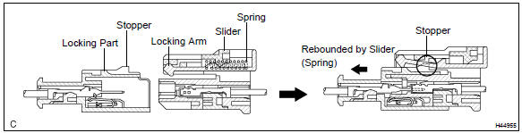
3. Half connection prevention mechanism: If the connector is not completely connected, the connector is disconnected due to the spring operation so that no continuity exists.
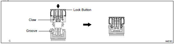
4. Connector lock mechanism 1.: Locking the connector lock button connects the connector securely.
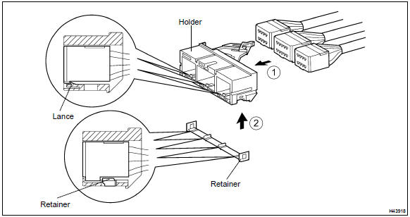
5. Connector lock mechanism 2.: Both the primary lock with holder lances and the secondary lock with retainer prevent the connectors from becoming disconnected.
6. Improper connection prevention lock mechanism: When connecting the holder, the lever is pushed into the end by rotating around the A axis to lock the holder securely.
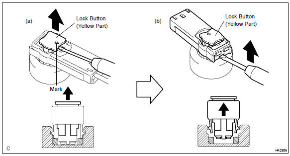
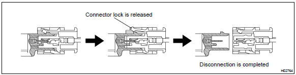
3. DISCONNECTION OF CONNECTORS FOR CURTAIN SHIELD AIRBAG ASSY (TMC MADE), HORN BUTTON ASSY AND FRONT PASSENGER AIRBAG ASSY
-
Release the lock button (yellow part) of the connector using a screwdriver.
-
Insert the screwdriver tip between the connector and the base, and then raise the connector.
 Disconnection of connectors for curtain shield airbag assy (TMC made), horn
button assy and front passenger airbag assy
Disconnection of connectors for curtain shield airbag assy (TMC made), horn
button assy and front passenger airbag assy
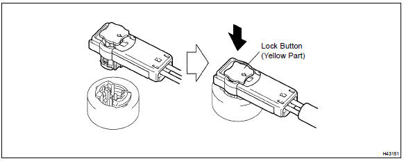
4. CONNECTION OF CONNECTORS FOR CURTAIN SHIELD AIRBAG ASSY (TMC MADE), HORN BUTTON ASSY AND FRONT PASSENGER AIRBAG ASSY
-
Connect the connector.
-
Push down securely on the lock button (yellow part) of the connector. (When locking, a click sound can be heard.)
 Connection of connectors for curtain shield airbag assy (TMC made), horn
button assy and front passenger airbag assy
Connection of connectors for curtain shield airbag assy (TMC made), horn
button assy and front passenger airbag assy
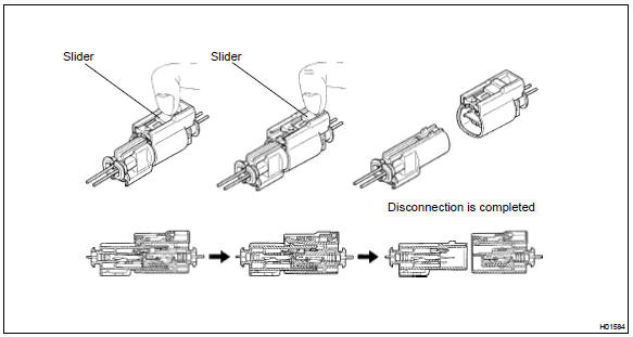
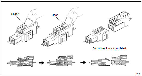
5. DISCONNECTION OF CONNECTOR FOR FRONT SEAT AIRBAG ASSY
a. Place a finger on the slider, slide the slider to release the lock, and then disconnect the connector.
 Disconnection of connector for front seat airbag assy
6. CONNECTION OF CONNECTOR FOR FRONT SEAT AIRBAG ASSY
a. Connect the connector as shown in the illustration. (When locking, make sure that the slider returns to its original position and a click sound can be heard.)
HINT: When connecting, the slider will slide. Be sure not to touch the slider while connecting, as it may result in an insecure fit.
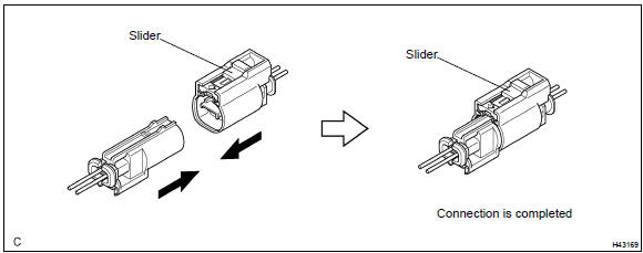 Connection of connector for front seat airbag assy
7. DISCONNECTION OF CONNECTOR FOR CURTAIN SHIELD AIRBAG ASSY (TMMK MADE)
a. Place a finger on the slider, slide the slider to release the lock, and then disconnect the connector.
 Disconnection of connector for curtain shield airbag assy (TMMK made)
8. CONNECTION OF CONNECTOR FOR CURTAIN SHIELD AIRBAG ASSY (TMMK MADE)
a. Connect the connector as shown in the illustration. (When locking, make sure that the slider returns to its original position and a click sound can be heard.)
HINT: When connecting, the slider will slide. Be sure not to touch the slider while connecting, as it may result in an insecure fit.
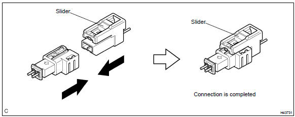 Connection of connector for curtain shield airbag assy (TMMK made)
9. DISCONNECTION OF CONNECTOR FOR AIRBAG SENSOR ASSY CENTER
a. Pull the lever by pushing part A as shown in the illustration and disconnect the holder (with connectors).
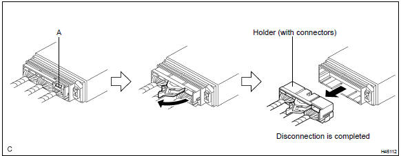
HINT: Perform the following procedures when replacing the holder.
b. Remove the holder.
1. Using a screwdriver, unlock the retainer.
2. Release the lances and remove the holder.
c. Install the holder.
1. Install the connectors to the holder. (When locking, a click sound can be heard.)
HINT: The retainer is locked when the holder is connected.
10. CONNECTION OF CONNECTOR FOR AIRBAG SENSOR ASSY CENTER
-
Firmly insert the holder (with connectors) until it can not be pushed any further.
-
Push the lever to connect the holder (with connectors). (When locking, a click sound can be heard.)
HINT: The holder slides when connecting. Be sure not to hold the holder while connecting, as it may result in an insecure fit.
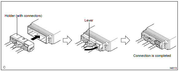 Connection of connector for airbag sensor assy center
11. DISCONNECTION OF CONNECTORS FOR AIRBAG FRONT SENSOR, SIDE AIRBAG SENSOR AND AIRBAG SENSOR REAR
-
While holding both outer flank sides, slide the outer in the direction shown by the arrow.
-
When the connector lock is released, the connectors are disconnected.
HINT: Be sure to hold both outer flank sides. Holding the top and bottom will make disconnection difficult.
12. CONNECTION OF CONNECTORS FOR AIRBAG FRONT SENSOR, SIDE AIRBAG SENSOR AND AIRBAG SENSOR REAR
a. Connect the connector as shown in the illustration. (When locking, make sure that the outer returns to its original position and a click sound can be heard.)
HINT: When connecting the outer slides. Be sure not to hold the outer while connecting, as it may result in an insecure fit.
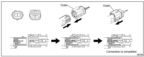 Connection of connectors for airbag front sensor, side airbag sensor and
airbag sensor rear
Connection of connectors for airbag front sensor, side airbag sensor and
airbag sensor rear
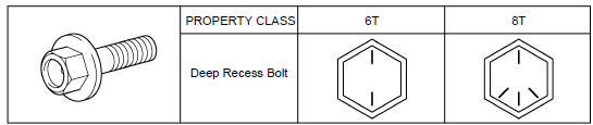
13. NOTICE REGARDING AIRBAG SENSOR INSTALLATION BOLT
a. As the tightening torque is different depending on the property class of the airbag sensor installation bolt, choose a bolt referring to the following illustration and tighten it with the specified tightening torque written in the repair manual.
ON−VEHICLE INSPECTION
CAUTION: Be sure to perform the initialization of the occupant classification ECU under the conditions listed below. If the initialization is not performed, the SRS may not operate properly.
-
The occupant classification ECU is replaced.
-
Accessories (seatback tray or seat cover, etc.) are installed to the vehicle.
-
The passenger seat is removed from the vehicle.
-
Both the SRS warning light and passenger airbag ON/OFF indicator light (”OFF”) come on.
-
The vehicle is brought to the workshop for repair purpose due to an accident or collision.
1. HORN BUTTON ASSY (VEHICLE NOT INVOLVED IN COLLISION)
HINT: There are two types of horn button assy: One is used with 3−spoke steering wheel assy and the other is used with 4−spoke steering wheel assy.
-
Perform a diagnostic system check.
-
With the horn button assy installed on the vehicle, perform a visual check. If there are any defects as mentioned below, replace the horn button assy with a new one: Cuts, minute cracks or marked discoloration on the horn button assy top surface or in the grooved portion.
 Horn button assy (vehicle not involved in collision)
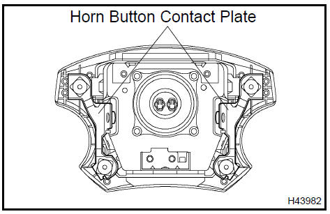
2. HORN BUTTON ASSY (VEHICLE INVOLVED IN COLLISION AND AIRBAG IS NOT DEPLOYED)
-
Perform a diagnostic system check.
-
With the horn button assy removed from the vehicle, perform a visual check. If there are any defects as mentioned below, replace the horn button assy or steering wheel assy with a new one:
-
Cuts, minute cracks or marked discoloration on the horn button assy top surface or in the grooved portion.
-
Cracks or other damage to the connector.
-
Deformation of the steering wheel assy.
-
Deformation of the horn button contact plate of the horn button assy.
-
There should be no interference between the horn button assy and steering wheel assy, and the clearance should be uniform all the way around when the new horn button assy is installed on the steering wheel assy.
CAUTION: For removal and installation procedures of the horn button assy, and be sure to follow the correct procedure.
3. FRONT PASSENGER AIRBAG ASSY (VEHICLE NOT INVOLVED IN COLLISION)
-
Perform a diagnostic system check.
-
With the front passenger airbag assy installed on the vehicle, perform a visual check. If there are any defects as mentioned below, replace the instrument panel with a new one:
Cuts, minute cracks or marked discoloration on the instrument panel around the doorless instrument panel passenger airbag assy.
 Front passenger airbag assy (vehicle not involved in collision)
4. FRONT PASSENGER AIRBAG ASSY (VEHICLE INVOLVED IN COLLISION AND AIRBAG IS NOT DEPLOYED)
-
Perform a diagnostic system check .
-
With the front passenger airbag assy removed from the vehicle, perform a visual check. If there are any defects as mentioned below, replace the front passenger airbag assy, instrument panel or instrument panel reinforcement with a new one:
-
Cuts, minute cracks or marked discoloration on the front passenger airbag assy.
-
Cracks or other damage to the connectors.
-
Deformation or cracks on the instrument panel or instrument panel reinforcement.
CAUTION: For removal and installation procedures of the front passenger airbag assy, and be sure to follow the correct procedure.
5. FRONT SEAT AIRBAG ASSY (VEHICLE NOT INVOLVED IN COLLISION)
-
Perform a diagnostic system check.
-
With the front seat airbag assy installed on the vehicle, perform a visual check. If there are any defects as mentioned below, replace the front seatback assy with a new one:
Cuts, minute cracks or marked discoloration on the front seatback assy around the front seat airbag assy.
 Front seat airbag assy (vehicle not involved in collision)
6. FRONT SEAT AIRBAG ASSY (VEHICLE INVOLVED IN COLLISION AND AIRBAG IS NOT DEPLOYED)
-
Perform a diagnostic system check.
-
With the front seat airbag assy removed from the vehicle, perform a visual check. If there are any defects as mentioned below, replace the front seat airbag assy with a new one:
-
Cuts, minute cracks or marked discoloration on the front seat airbag assy.
-
Cracks or other damage to the wire harness or connector.
CAUTION: For removal and installation procedures of the front seat airbag assy, and be sure to follow the correct procedure
 Front seat airbag assy (vehicle involved in collision and airbag is not
deployed)
Front seat airbag assy (vehicle involved in collision and airbag is not
deployed)
7. CURTAIN SHIELD AIRBAG ASSY (VEHICLE NOT INVOLVED IN COLLISION)
-
Perform a diagnostic system check.
-
With the curtain shield airbag assy installed on the vehicle, perform a visual check. If there are any defects as mentioned below, replace the front pillar garnish or roof headlining assy with a new one: Cuts, minute cracks or marked discoloration on the front pillar garnish or roof headlining assy around the curtain shield airbag assy
 Curtain shield airbag assy (vehicle not involved in collision)
8. CURTAIN SHIELD AIRBAG ASSY (VEHICLE INVOLVED IN COLLISION AND AIRBAG IS NOT DEPLOYED)
-
Perform a diagnostic system check.
-
With the curtain shield airbag assy removed from the vehicle, perform a visual check. If there are any defects as mentioned below, replace the curtain shield airbag assy with a new one:
-
Cuts, minute cracks or marked discoloration on the curtain shield airbag assy.
-
Cracks or other damage to the connector.
CAUTION: For removal and installation procedures of the curtain shield airbag assy, and be sure to follow the correct procedure.
 Curtain shield airbag assy (vehicle involved in collision and airbag is not
deployed)
Curtain shield airbag assy (vehicle involved in collision and airbag is not
deployed)
9. AIRBAG SENSOR ASSY CENTER (VEHICLE NOT INVOLVED IN COLLISION
)
a. Perform a diagnostic system check.
10. AIRBAG SENSOR ASSY CENTER (VEHICLE INVOLVED IN COLLISION AND AIRBAG IS NOT DEPLOYED)
a. Perform a diagnostic system check .
11. AIRBAG SENSOR ASSY CENTER (VEHICLE INVOLVED IN COLLISION AND AIRBAG IS DEPLOYED)
a. Replace the airbag sensor assy center
CAUTION: For removal and installation procedures of the airbag sensor assy center, and be sure to follow the correct procedure.
HINT: The airbag sensor assy center should be replaced after any of the airbags has deployed, as it has been subjected to the impact.
12. AIRBAG FRONT SENSOR (VEHICLE NOT INVOLVED IN COLLISION)
a. Perform a diagnostic system check .
13. AIRBAG FRONT SENSOR (VEHICLE INVOLVED IN COLLISION AND AIRBAG IS NOT DEPLOYED)
-
Perform a diagnostic system check.
-
When the front bumper of the vehicle or its periphery is damaged, check if there is any damage to the airbag sensor front. If any of the airbag sensor front have defects as mentioned below, replace it with a new one:
-
Cracks, dents or chips in the case.
-
Cracks or other damage to the connector.
-
Peeling off of the label or damage to the serial number.
CAUTION: For removal and installation procedures of the airbag sensor front, see page 60−63, and be sure to follow the correct procedure.
14. AIRBAG FRONT SENSOR (VEHICLE INVOLVED IN COLLISION AND AIRBAG IS DEPLOYED)
a. Replace the airbag front sensor.
CAUTION: For removal and installation procedures of the airbag sensor front, see page 60−63, and be sure to follow the correct procedure.
HINT: The airbag sensor front on the impacted side should be replaced after the horn button assy or front passenger airbag assy has deployed.
15. SIDE AIRBAG SENSOR ASSY (VEHICLE NOT INVOLVED IN COLLISION)
a. Perform a diagnostic system check.
16. SIDE AIRBAG SENSOR ASSY (VEHICLE INVOLVED IN COLLISION AND AIRBAG IS NOT DEPLOYED)
-
Perform a diagnostic system check.
-
When the center pillar of the vehicle or its periphery is damaged, check if there is any damage to the side airbag sensor assy. If there are any defects as mentioned below, replace the side airbag sensor assy with a new one:
-
Cracks, dents or chips in the case.
-
Cracks or other damage to the connector.
-
Peeling off of the label or damage to the serial number.
CAUTION: For removal and installation procedures of the side airbag sensor assy, see page 60−65, and be sure to follow the correct procedure.
17. SIDE AIRBAG SENSOR ASSY (VEHICLE INVOLVED IN COLLISION AND AIRBAG IS DEPLOYED)
a. Replace the side airbag sensor assy.
CAUTION: For removal and installation procedures of the side airbag sensor assy, and be sure to follow the correct procedure.
HINT: The side airbag sensor assy on the impacted side should be replaced after the front seat airbag assy and curtain shield airbag assy have deployed.
18. AIRBAG SENSOR REAR (VEHICLE NOT INVOLVED IN COLLISION)
a. Perform a diagnostic system check.
19. AIRBAG SENSOR REAR (VEHICLE INVOLVED IN COLLISION AND AIRBAG IS NOT DEPLOYED)
-
Perform a diagnostic system check.
-
When the quarter panel of the vehicle or its periphery is damaged, check if there is any damage to the airbag sensor rear. If there are any defects as mentioned below, replace the airbag sensor rear with a new one:
-
Cracks, dents or chips in the case.
-
Cracks or other damage to the connector.
-
Peeling off of the label or damage to the serial number.
CAUTION: For removal and installation procedures of the airbag sensor rear, and be sure to follow the correct procedure.
20. AIRBAG SENSOR REAR (VEHICLE INVOLVED IN COLLISION AND AIRBAG IS DEPLOYED)
a. Replace the airbag sensor rea.
CAUTION: For removal and installation procedures of the airbag sensor rear, and be sure to follow the correct procedure.
HINT: The airbag sensor rear on the impacted side should be replaced after the curtain shield airbag assy has deployed.
21. SEAT POSITION AIRBAG SENSOR (VEHICLE NOT INVOLVED IN COLLISION)
a. Perform a diagnostic system check.
22. SEAT POSITION AIRBAG SENSOR (VEHICLE INVOLVED IN COLLISION)
-
Perform a diagnostic system check.
-
Even if the airbag was not deployed, perform a visual check for damage to the seat position airbag sensor including the following:
-
Cracks, dents or chips in the case.
-
Cracks or other damage to the connector.
CAUTION: For removal and installation procedures of the seat position airbag sensor, and be sure to follow the correct procedure.
23. OCCUPANT CLASSIFICATION ECU (VEHICLE NOT INVOLVED IN COLLISION)
a. Perform a diagnostic system check.
24. OCCUPANT CLASSIFICATION ECU (VEHICLE INVOLVED IN COLLISION)
-
Perform a diagnostic system check.
-
Even if the airbag was not deployed, perform a visual check for damage to the occupant classification ECU including the following:
-
Cracks, dents or chips in the case.
-
Cracks or other damage to the connector.
CAUTION: For removal and installation procedures of the occupant classification ECU, and be sure to follow the correct procedure.
25. WIRE HARNESS AND CONNECTOR (VEHICLE NOT INVOLVED IN COLLISION)
a. Perform a diagnostic system check.
26. WIRE HARNESS AND CONNECTOR (VEHICLE INVOLVED IN COLLISION)
-
Perform a diagnostic system check .
-
Check for breaks in all wires of the SRS wire harness and exposed conductors.
-
Check to see if the SRS wire harness connectors are cracked or chipped.
HINT: The SRS wire harness is integrated with the engine room main wire, instrument panel wire, instrument panel wire No.2, floor wire, floor wire No.2, front seat LH wire (TMC made) and front seat RH wire.
- Horn button assy
- Spiral cable sub-assy
- Front passenger airbag assy (From July, 2003)
- Curtain shield air bag assy LH
- Front seat airbag assy RH
- Air bag sensor assy center
- Air bag front RH sensor
- Air bag sensor front LH
- Air bag sensor front LH
- Air bag sensor front LH
- Side air bag sensor assy RH
- Air bag sensor rear LH
- Seat position air bag sensor (From July, 2003)
- Occupant classification ecu (From July, 2003)
Introduction
Audio & visual system
Automatic transmission / trans
Brake
Clutch
Communication system
Cooling
Cruise control
Drive shaft / propeller shaft
Emission control
Engine control system
Engine hood/door
Engine mechanical
Exhaust
Exterior/interior trim
Front suspension
Fuel
Heater & air conditioner
Ignition
Instrument panel/meter
Intake
Lighting
Lubrication
Manual transmission/transaxle
Parking brake
Power steering
Rear suspension
Seat
Service specifications
Sliding roof/convertible
Starting & charging
Steering column
Supplemental restraint system
Theft deterrent & door lock
Tire & wheel
Windshield/windowglass/mirror
Wiper & washer
Wiring
Toyota Camry XV30 (2002–2006) Service Manual
- Introduction
- Audio & visual system
- Automatic transmission / trans
- Brake
- Clutch
- Communication system
- Cooling
- Cruise control
- Drive shaft / propeller shaft
- Emission control
- Engine control system
- Engine hood/door
- Engine mechanical
- Exhaust
- Exterior/interior trim
- Front suspension
- Fuel
- Heater & air conditioner
- Ignition
- Instrument panel/meter
- Intake
- Lighting
- Lubrication
- Manual transmission/transaxle
- Parking brake
- Power steering
- Rear suspension
- Seat
- Service specifications
- Sliding roof/convertible
- Starting & charging
- Steering column
- Supplemental restraint system
- Theft deterrent & door lock
- Tire & wheel
- Windshield/windowglass/mirror
- Wiper & washer
- Wiring
Categories
