 Toyota Camry XV30 (2002–2006) Service ManualDrive shaft / propeller shaft
Front drive shaft (From July, 2003)
Front drive shaft (From July, 2003)
OVERHAUL
HINT:
-
COMPONENTS
-
Use the same procedures for the RH side and LH side.
-
The Procedures listed below are for the LH side.
-
DRAIN AUTOMATIC TRANSAXLE FLUID (A/T TRANSAXLE)
-
DRAIN MANUAL TRANSAXLE OIL (M/T TRANSAXLE)
-
REMOVE FRONT WHEEL
-
REMOVE FRONT AXLE HUB LH NUT
a. Using SST and a hammer, unstake the staked part of the axle hub LH nut.
SST 09930−00010
NOTICE: Loosen the staked part of the lock nut completely, otherwise the screw of the drive shaft may be damaged.
b. While applying the brakes, remove the front axle hub LH nut.
Remove front axle hub LH nut
5. DISCONNECT FRONT STABILIZER LINK ASSY LH
a. Remove the nut, and separate the stabilizer link assy LH.
HINT: If the ball joint turns together with the nut, use a hexagon wrench (6 mm) to hold the stud.
Disconnect front stabilizer link assy LH
6. DISCONNECT SPEED FRONT LH (W/ ABS)
a. Remove the bolt and clip, and separate the wire and hose from the shock absorber.
NOTICE: Be careful not to damage the speed .
b. Remove the bolt, and separate the speed front LH from the steering knuckle.
NOTICE: Prevent foreign matter from adhering to the speed .
7. DISCONNECT TIE ROD ASSY LH
-
Remove the cotter pin and nut.
-
Using SST, separate the tie rod end from the steering knuckle.
SST 09628−62011
Disconnect tie rod assy LH
8. DISCONNECT FRONT SUSPENSION ARM SUB−ASSY LOWER No.1 LH
a. Remove the bolt and 2 nuts, and disconnect the front suspension arm sub−assy lower No.1 LH from the lower ball joint.
Disconnect front suspension arm sub-assy lower No.1 LH
9. DISCONNECT FRONT AXLE ASSY LH
a. Using a plastic hammer, separate the drive shaft from the axle hub.
NOTICE: Be careful not to damage the boot and speed rotor.
(w/ABS
)
Disconnect front axle assy LH
10. REMOVE FRONT DRIVE SHAFT ASSY LH
a. Using SST, remove the front drive shaft assy LH.
SST 09520−01010, 09520−24010 (09520−32040)
NOTICE: Be careful not to damage the transaxle case oil seal, inboard joint boot and drive shaft dust cover.
Be careful not to drop the drive shaft assy.
Remove front drive shaft assy LH
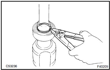
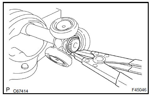
11. REMOVE FRONT DRIVE SHAFT ASSY RH
-
Using pliers, remove the drive shaft bearing bracket hole snap ring.
-
Remove the bolt and front drive shaft assy RH from the drive shaft bearing bracket.
Remove front drive shaft assy LH
12. FIX FRONT AXLE ASSY LH
SST 09608−16042 (09608−02021, 09608−02041)
NOTICE: The hub bearing could be damaged if it is subjected to the vehicle’s full weight, such as when moving the vehicle with the drive shaft removed.
Therefore, if it is absolutely necessary to place the vehicle weight on the hub bearing, first support it with SST.
Fix front axle assy LH
13. INSPECT FRONT DRIVE SHAFT ASSY LH
-
Check that there is no remarkable play in the radial direction of the outboard joint.
-
Check that the inboard joint slides smoothly in the thrust direction.
-
Check that there is no remarkable play in the radial direction of the inboard joint.
-
Check the boots for damage.
Inspect front drive shaft assy LH
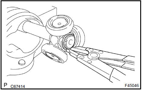
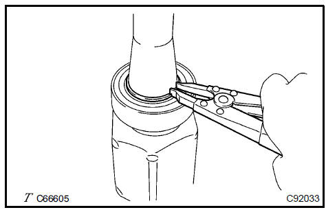
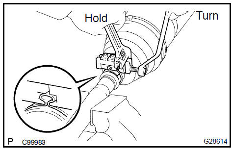
14. REMOVE FRONT AXLE INBOARD JOINT BOOT LH No.2 CLAMP
a. Using pliers, remove the inboard joint boot LH No.2 clamp, as shown in the illustration.
Remove front axle inboard joint boot LH No.2 clamp
15. REMOVE FRONT AXLE INBOARD JOINT BOOT LH CLAMP
a. Remove the inboard joint boot LH clamp using the same procedures as for the inboard joint boot LH clamp.
 Remove front axle inboard joint boot LH clamp
16. DISCONNECT FR AXLE INBOARD JOINT BOOT
a. Separate the inboard joint boot from the inboard joint assy.
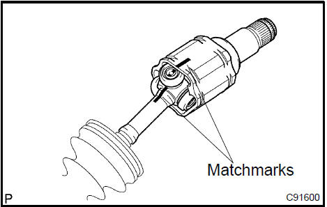
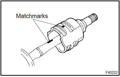
17. REMOVE FRONT DRIVE INBOARD JOINT ASSY LH
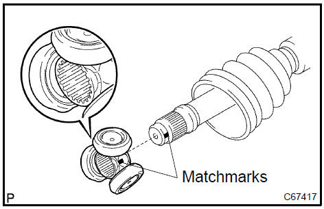
a. Put matchmarks on the inboard joint assy and outboard joint shaft.
NOTICE: Do not use a punch for the marks.
b. Remove the inboard joint assy from the outboard joint shaft.
c. Using a snap ring expander, remove the front drive inner shaft inner RH shaft snap ring.
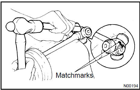
d. Put matchmarks on the outboard joint shaft and tripod joint.
NOTICE: Do not use a punch for the marks.
e. Using a brass bar and a hammer, remove the tripod joint from the outboard joint shaft.
NOTICE: Do not tap the roller.
HINT: This procedure is unnecessary for a manual transaxle vehicle because it does not have a drive shaft damper.
18. REMOVE FRONT DRIVE SHAFT DAMPER LH (EXCEPT MANUAL TRANSAXLE)
-
Using pliers, remove the drive shaft damper clamp, as shown in the illustration.
-
Remove the drive shaft damper.
19. REMOVE FRONT DRIVE SHAFT DAMPER RH (EXCEPT 1MZ−FE ENGINE TYPE)
-
Using pliers, remove the drive shaft damper clamp, as shown in the illustration.
-
Remove the drive shaft damper.
Remove front drive shaft damper RH (except 1MZ-FE engine type)
20. REMOVE FRONT AXLE OUTBOARD JOINT BOOT LH No.2 CLAMP
a. Using pliers, remove the outboard joint boot LH No.2 clamp, as shown in the illustration.
Remove front axle outboard joint boot LH No.2 Clamp
21. REMOVE FRONT AXLE OUTBOARD JOINT BOOT LH CLAMP
a. Remove the outboard joint boot LH clamp using the same procedures as for the outboard joint boot LH No.2 clamp.
Remove front axle outboard joint boot LH clamp
22. REMOVE OUTBOARD JOINT BOOT
-
Remove the outboard joint boot from the outboard joint shaft.
-
Remove the old grease from the outboard joint.
3. REMOVE FRONT WHEEL BEARING DUST DEFLECTOR LH No.2 (W/O ABS)
-
Mount the front drive outboard joint shaft assy LH in a soft jaw vise.
-
Using a screwdriver and a hammer, remove the front wheel bearing dust deflector LH No.2.
Remove front wheel bearing dust deflector LH No.2 (W/O ABS)
24. REMOVE FRONT DRIVE SHAFT LH HOLE SNAP RING
a. Using a screwdriver, remove the hole snap ring.
Remove front drive shaft LH hole snap ring
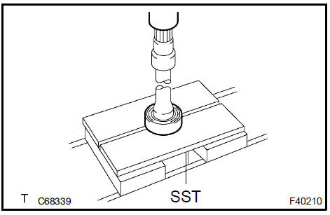
25. REMOVE FRONT DRIVE SHAFT DUST COVER LH
a. Using SST and a press, remove the front drive shaft dust cover LH.
SST 09950−00020
NOTICE: Be careful not to drop the inboard joint assy.
Remove front drive shaft dust cover LH
26. REMOVE FRONT DRIVE SHAFT DUST COVER RH
a. Using a press, remove the front drive shaft dust cover RH.
Remove front drive shaft dust cover RH
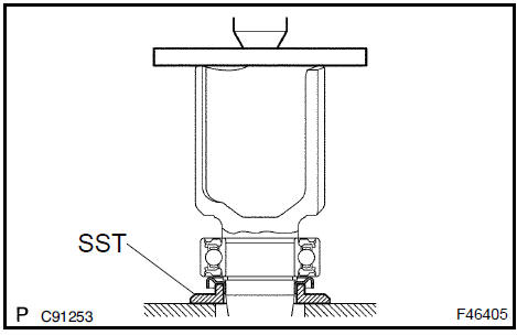
27. REMOVE FRONT DRIVE SHAFT DUST COVER
a. Using SST and a press, remove the front drive shaft dust cover.
SST 09950−00020
Remove front drive shaft dust cover
28. REMOVE FRONT DRIVE SHAFT BEARING
a. Using snap ring pliers, remove the front drive shaft hole snap ring RH.
b. Using SST and a press, remove the bearing.
SST 09527−10011
NOTICE: Be careful not to drop the inboard joint assy.
29. INSTALL FRONT DRIVE SHAFT BEARING
a. Using SST and a steel plate, install a new front drive shaft bearing.
SST 09527−30010, 09527−10011
NOTICE: Bearing should be completely installed.
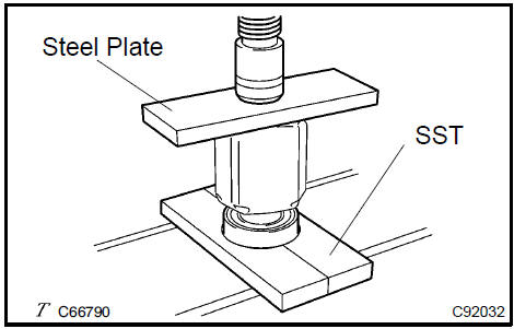
b. Using a snap ring expander, install a new front drive shaft hole snap ring RH.
30. INSTALL FRONT DRIVE SHAFT DUST COVER
a. Using SST and a press, install a new drive shaft dust cover.
SST 09726−40010
NOTICE:
-
Dust cover should be completely installed.
-
Be careful not to damage the dust cover.
Install front drive shaft dust cover
31. INSTALL FRONT DRIVE SHAFT DUST COVER RH
a. Using SST and a press, install a new drive shaft dust cover RH until the distance from the tip of the center drive shaft to the drive shaft dust cover RH meets the specification, as shown in the illustration.
SST 09527−10011
Distance a.: 1MZ−FE, 3MZ−FE: 110.5 0.5 mm (4.3 0.02 in.) 2AZ−FE: 91.5 0.5 mm (3.6 0.02 in.)
NOTICE:
-
Dust cover should be completely installed.
-
Be careful not to damage the dust cover.
Install front drive shaft dust cover RH
32. INSTALL FRONT DRIVE SHAFT DUST COVER LH
a. Using SST and a press, install a new front drive shaft dust cover LH.
SST 09527−10011
NOTICE:
-
Dust cover should be completely installed.
-
Be careful not to damage the dust cover.
Install front drive shaft dust cover LH
33. INSTALL FRONT DRIVE SHAFT LH HOLE SNAP RING
a. Install a new front drive shaft LH hole snap ring.
34. INSTALL FRONT WHEEL BEARING DUST DEFLECTOR LH No.2 (W/O ABS)
a. Using SST and a press, install a new front wheel bearing dust deflector LH No.2 until the distance from the tip of front drive outboard joint shaft assy LH to the front wheel bearing dust deflector LH No.2 reaches the specification, as shown in the illustration.
SST 09387−00020
Distance: 13.5 − 13.8 mm (0.531 − 0.543 in.)
 Install front drive shaft LH hole snap ring
35. INSTALL OUTBOARD JOINT BOOT
HINT: Before installing the boots, wrap the spline of the drive shaft with vinyl tape to prevent the boots from being damaged.
-
Hold the drive shaft lightly in a soft vise.
-
Temporarily install a new outboard joint boot with 2 clamps to the drive shaft.
-
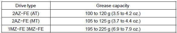
Pack the outboard joint shaft and boot with grease.
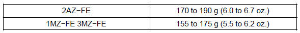
Grease capacity:
Install outboard joint boot
36. INSTALL FRONT AXLE OUTBOARD JOINT BOOT LH No.2 CLAMP
-
(Install the 2 outboard joint boot clamps onto the boot.
-
Place SST onto the outboard joint boot LH No.2 clamp.
SST 09521−24010
-
Tighten the SST so that the outboard joint boot LH No.2 clamp is pinched.
NOTICE: Do not overtighten the SST.
d. Using SST, measure the clearance of the outboard joint boot LH No.2 clamp.
SST 09240−00020
Clearance: 3.0 to 4.0 mm (0.118 to 0.157 in.)
NOTICE: When the measured value is greater than the specified value, retighten the clamp.
37. INSTALL FRONT AXLE OUTBOARD JOINT BOOT LH CLAMP
a. The procedure for the outboard joint boot LH clamp is the same as above.
SST 09521−24010, 09240−00020 Clearance: 1.5 to 2.5 mm (0.059 to 0.098 in.)
38. INSTALL FRONT DRIVE SHAFT DAMPER LH (EXCEPT MANUAL TRANSAXLE)
-
Install the drive shaft damper LH to the drive shaft.
-
Make sure that the damper is on the shaft groove.
-
Set the distance, as described below.
Distance: 207 2.0 mm (8.15 0.079 in.)
HINT: This procedure is unnecessary for a manual transaxle vehicle because it does not have a drive shaft damper.
-
Place SST onto the front drive shaft damper LH clamp.
SST 09521−24010
-
Tighten the SST so that the front drive shaft damper LH clamp is pinched.
NOTICE: Do not overtighten the SST.
f. Using SST, measure the clearance of the drive shaft damper clamp.
SST 09240−00020
Clearance: 0.5 to 1.2 mm (0.020 to 0.047 in.)
NOTICE: When the measured value is greater than the specified value, retighten the clamp.
39. INSTALL FRONT DRIVE SHAFT DAMPER RH (EXCEPT 1MZ−FE ENGINE TYPE)
-
Install the drive shaft damper RH to the drive shaft.
-
Make sure that the damper is on the shaft groove.
-
Set the distance, as described below.
Distance: 207 2.0 mm (8.15 0.079 in.)
-
Place SST onto the front drive shaft damper RH clamp.
SST 09521−24010
-
Tighten the SST so that the front drive shaft damper RH clamp is pinched.
NOTICE: Do not overtighten the SST.
f. Using SST, measure the clearance of the outboard joint boot RH No.2 clamp.
SST 09240−00020
Clearance: 0.5 to 1.2 mm (0.020 to 0.047 in.)
NOTICE: When the measured value is greater than the specified value, retighten the clamp.
40. INSTALL FRONT DRIVE INBOARD JOINT ASSY LH
-
Temporarily install a new inboard joint boot with 2 clamps to the drive shaft.
-
Place the beveled side of the tripod joint axial spline toward the outboard joint shaft.
-
Align the matchmarks.
-
Using a brass bar and a hammer, tap in the tripod joint to the outboard joint shaft.
NOTICE:
-
Do not tap the roller.
-
Be sure to install the tripod joint assy in the correct direction.
e. Using a snap ring expander, install a new shaft snap ring.
f. Pack the outboard joint shaft and boot with grease.
Grease capacity:
g. Align the matchmarks and install the inboard joint assy to the outboard joint shaft assy.
41. INSTALL FR AXLE INBOARD JOINT BOOT
a. Install the inboard joint boot to the inboard joint assy.
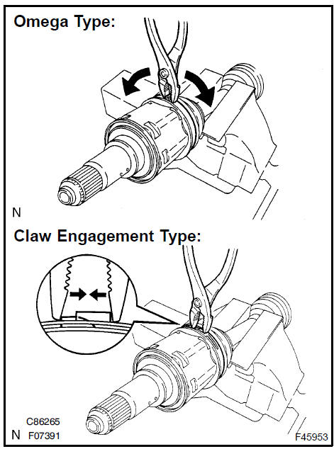
42. INSTALL FRONT AXLE INBOARD JOINT BOOT LH No.2 CLAMP
a. Claw Engagement
1. Using pliers, install the inboard joint boot LH No.2 clamp, as shown in the illustration.
b. Omega Clamp Type: Install new inboard joint boot clamps.
1. Hold the drive shaft lightly in a soft vise.
2. Install 2 new inboard joint boot clamps to the boot.
3. Place SST onto the inboard joint boot LH No.2 clamp.
SST 09521−24010
4. Tighten the SST so that the inboard joint boot LH No.2 clamp is pinched.
NOTICE: Do not overtighten the SST.
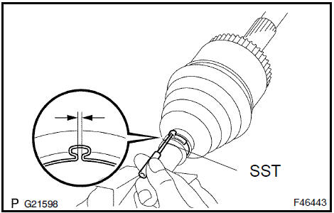
5. Using SST, measure the clearance of the inboard joint boot LH No.2 clamp.
SST 09240−00020
Clearance: 1.9 mm (0.075 in.) or less
NOTICE: When the measured value is greater than the specified value, retighten the clamp.
43. INSTALL FRONT AXLE INBOARD JOINT BOOT LH CLAMP
a. Install new inboard joint boot clamps.
-
Hold the drive shaft lightly in a soft vise.
-
Install 2 new inboard joint boot clamps to the boot.
-
Place SST onto the inboard joint boot LH clamp.
SST 09521−24010, 09240−00020
-
Tighten the SST so that the inboard joint boot LH clamp is pinched.
NOTICE: Do not overtighten the SST.
5. Using SST, measure the clearance of the inboard joint boot LH clamp.
SST 09240−00020
Clearance: 1.9 mm (0.075 in.) or less
NOTICE: When the measured value is greater than the specified value, retighten the clamp.
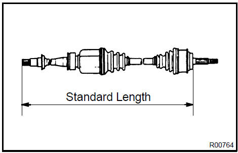
44. INSPECT FRONT DRIVE SHAFT
-
Check that there is no remarkable play in the radial direction of the outboard joint.
-
Check that the inboard joint slides smoothly in the thrust direction.
-
Check that there is no remarkable play in the radial direction of the inboard joint.
-
Check the boots for damage.
-
Make sure that the 2 boots are on the shaft groove.
-
Make sure that the 2 boots are not stretched or contracted when the drive shaft is at standard length.
Drive shaft standard length: mm (in.)
1MZ−FE, 3MZ−FE:
2AZ−FE:
45. INSTALL FRONT DRIVE SHAFT ASSY LH
-
Coat the spline of the inboard joint shaft assy with ATF.
-
Align the shaft splines and install the drive shaft assy with a brass bar and a hammer.
NOTICE:
-
Set the snap ring with the opening side facing downward.
-
Be careful not to damage the oil seal boot and dust cover.
-
Move the drive shaft assy while keeping it level.
 Install front drive shaft assy LH
46. INSTALL FRONT DRIVE SHAFT ASSY RH
a. Using a screwdriver, install a new bearing bracket hole snap ring.
NOTICE: Do not damage the oil seal and boot.
b. Install the bolt.
Torque: 32 N·m (330 kgf·cm, 24 ft·lbf)
Install front drive shaft assy LH
47. INSTALL FRONT AXLE ASSY LH
a. Install the front drive shaft assy LH to the front axle assy LH.
NOTICE:
-
Be careful not to damage the outboard joint boot.
-
w/ ABS: Be careful not to damage the speed rotor.
48. INSTALL FRONT SUSPENSION ARM SUB−ASSY LOWER No.1 LH
a. Install the lower ball joint to the front suspension arm sub− assy lower with the bolt and nuts.
Torque: 75 N·m (765 kgf·cm, 55 ft·lbf)
 Install front suspension arm sub-assy lower No.1 LH
49. INSTALL TIE ROD ASSY LH
-
Install the tie rod end to the steering knuckle with the nut.
Torque: 49 N·m (500 kgf·cm, 36 ft·lbf)
-
Install a new cotter pin.
NOTICE: If the holes for the cotter pin are not aligned, further tighten the nut up to 60 .
50. INSTALL SPEED FRONT LH (W/ ABS)
a. Install the flexible hose and the speed to the shock absorber with the bolt and set the clip of on knuckle.
Torque: 19 N·m (192 kgf·cm, 13 ft·lbf)
NOTICE:
-
Be careful not to damage the speed .
-
Prevent foreign matter from adhering to the speed .
-
Do not twist the wire when installing the speed .
b. Install the speed to the steering knuckle with the bolt.
Torque: 8.0 N·m (82 kgf·cm, 71 in.·lbf)
NOTICE: Prevent foreign matter from adhering to the speed .
51. INSTALL FRONT STABILIZER LINK ASSY LH
a. Install the front stabilizer link assy LH with the nut.
Torque: 74 N·m (755 kgf·cm, 55 ft·lbf)
HINT: If the ball joint turns together with the nut, use a hexagon (6 mm) wrench to hold the stud.
Install front stabilizer link assy LH
52. INSTALL FRONT AXLE HUB LH NUT
-
Using a socket wrench (30 mm), install a new axle hub LH nut.
Torque: 294 N·m (2,998 kgf·cm, 217 ft·lbf) -
(Using a chisel and a hammer, stake the front axle hub LH nut.
 Install front axle hub LH nut
-
INSTALL FRONT WHEEL
-
ADD AUTOMATIC TRANSAXLE FLUID (A/T TRANSAXLE)
-
INSPECT AUTOMATIC TRANSAXLE FLUID (A/T TRANSAXLE)
-
ADD MANUAL TRANSAXLE OIL (M/T TRANSAXLE)
-
INSPECT MANUAL TRANSAXLE OIL (M/T TRANSAXLE)
-
INSPECT AND ADJUST FRONT WHEEL ALIGNMENT
-
CHECK ABS SPEED SIGNAL (W/ ABS)
-
ABS WITH EBD SYSTEM (BOSCH MADE)
-
ABS WITH EBD SYSTEM (DENSO MADE)
-
ABS WITH EBD & BA & TRAC & VSC SYSTEM
Drive shaft, propeller shaft, axle (From July, 2003)
Front axle hub sub-assy LH (From July, 2003)
Front axle lh hub bolt
Rear axle hub & bearing assy LH
Rear axle LH hub bolt
Rear axle carrier sub-assy LH
Drive shaft, propeller shaft, axle (From July, 2003)
Front drive shaft (From July, 2003)
Toyota Camry XV30 (2002–2006) Service Manual
- Introduction
- Audio & visual system
- Automatic transmission / trans
- Brake
- Clutch
- Communication system
- Cooling
- Cruise control
- Drive shaft / propeller shaft
- Emission control
- Engine control system
- Engine hood/door
- Engine mechanical
- Exhaust
- Exterior/interior trim
- Front suspension
- Fuel
- Heater & air conditioner
- Ignition
- Instrument panel/meter
- Intake
- Lighting
- Lubrication
- Manual transmission/transaxle
- Parking brake
- Power steering
- Rear suspension
- Seat
- Service specifications
- Sliding roof/convertible
- Starting & charging
- Steering column
- Supplemental restraint system
- Theft deterrent & door lock
- Tire & wheel
- Windshield/windowglass/mirror
- Wiper & washer
- Wiring
Categories
