 Toyota Camry XV30 (2002–2006) Service ManualInstrument panel/meter
Instrument panel safety pad sub-assy
Instrument panel safety pad sub-assy
PRECAUTION
1. PRECAUTION FOR VEHICLE WITH SRS AIRBAG AND SEAT BELT PRETENSIONER
a. Some operations in this section may affect the SRS airbags. Prior to performing the corresponding operations, read the SRS airbag NOTICE
REPLACEMENT
HINT:
- COMPONENTS:
- Installation is in the reverse order of removal.
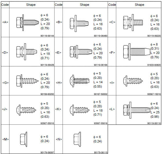
1. TABLE OF BOLT, SCREW AND NUT
HINT: All bolts, screws and nuts relevant to installing and removing the instrument panel are shown along with their alphabet code in the table below.
mm (in.) (L = Length)
- DISCONNECT BATTERY NEGATIVE TERMINAL
- REMOVE STEERING WHEEL COVER LOWER No.2
- REMOVE STEERING WHEEL COVER LOWER No.3
- REMOVE HORN BUTTON ASSY
- REMOVE STEERING WHEEL ASSY
SST 09950−50013 (09951−05010, 09952−05010, 09953−05020, 09954−05021)
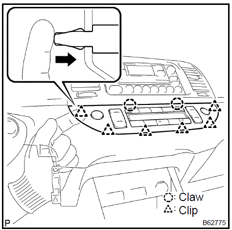
- REMOVE INSTRUMENT CLUSTER FINISH PANEL
a. Disengage the 4 clips and remove the instrument cluster finish panel.
 M
Remove instrument cluster finish panel
M
Remove instrument cluster finish panel
- REMOVE STEERING COLUMN COVER
- REMOVE HEADLAMP DIMMER SWITCH ASSY
- REMOVE WINDSHIELD WIPER SWITCH ASSY
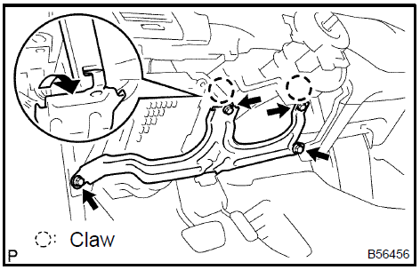
- REMOVE COMBINATION METER ASSY
- Remove the 2 screws and disengage the 2 clips.
- Pull out the combination meter assy, then disconnect the connectors.
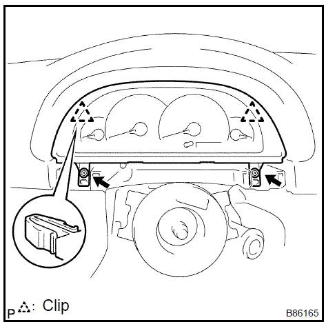 Remove combination meter assy
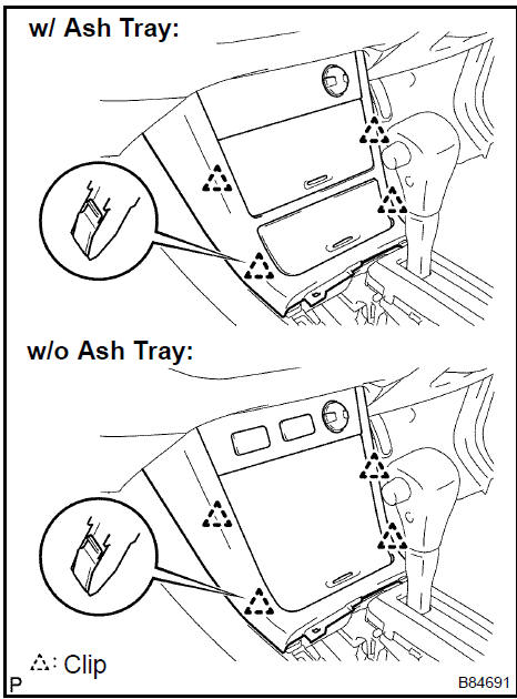
12. REMOVE FRONT DOOR SCUFF PLATE LH
a. Disengage the 7 claws and 4 clips then remove the front door scuff plate LH.
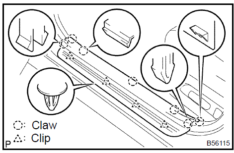 Remove front door scuff plate LH
13. REMOVE FRONT DOOR SCUFF PLATE RH
HINT: Use the same procedures for the RH side and LH side.
14. REMOVE INSTRUMENT PANEL UNDER COVER SUB−ASSY No.1
- Disengage the 3 claws and pin.
- Remove the instrument panel under cover sub−assy No.1.
 Remove instrument panel under cover sub-assy No.1
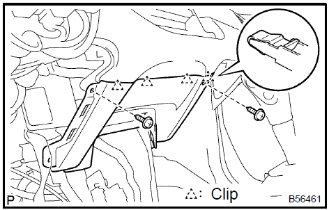
15. REMOVE COWL SIDE TRIM SUB−ASSY LH
- Remove the clip.
- Disengage the 2 clips and remove the cowl side trim sub− assy LH.
 Remove cowl side trim sub-assy LH
16. REMOVE COWL SIDE TRIM SUB−ASSY RH
HINT: Use the same procedures for the RH side and LH side.
17. REMOVE INSTRUMENT PANEL COIN BOX SUB−ASSY
a. Disengage the claw and remove the instrument panel coin box sub−assy.
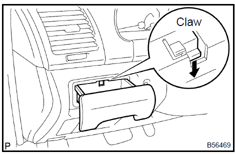 Remove instrument panel coin box sub-assy
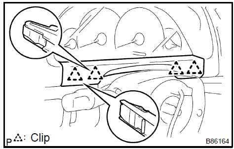
18. REMOVE INSTRUMENT PANEL SUB−ASSY UPPER
- Disconnect the hood lock control cable.
- Using a screwdriver, open the instrument panel sub−assy upper cover.
HINT: Tape the screwdriver tip before use.
- TMC made: Remove the bolt <E> and 2 screws <K>.
- TMMK made: Remove the bolt <D> and 2 screws <H>.
- Disengage the 3 clips.
- Disconnect the connectors and remove the instrument panel sub−assy upper.
 Remove instrument panel sub-assy upper
19. REMOVE INSTRUMENT PANEL INSERT LOWER
- TMC made: Remove the 4 bolts <L>.
- TMMK made: Remove the 4 bolts <A>.
- Disengage the 2 claws and remove the instrument panel insert lower.
 Remove instrument panel insert lower
20. REMOVE AIR CONDITIONER CONTROL ASSEMBLY (AUTO AIR CONDITIONING)
- Put in a hand from the position indicated in the illustration and push out the clip with fingers.
- Remove the remaining clips, disengage the claws, and then take off the air conditioner control assembly.
NOTICE:
- Perform this procedure wearing the protection gloves.
- Do not use any tools to avoid damage to the instrument panel safety pad sub−assembly.
 Remove air conditioner control assembly (auto air conditioning)
21. REMOVE AIR CONDITIONING PANEL SUB−ASSY (MANUAL AIR CONDITIONING)
HINT: Use the same procedures for the air conditioner control assembly and air conditioning panel sub−assy.
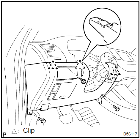
22. REMOVE INSTRUMENT CLUSTER FINISH PANEL SUB−ASSY CENTER
- Remove the 4 bolts.
- Using a moulding remover, disengage 5 clips, remove the instrument cluster finish panel sub−assy center with radio receiver assy, then disconnect the connectors.
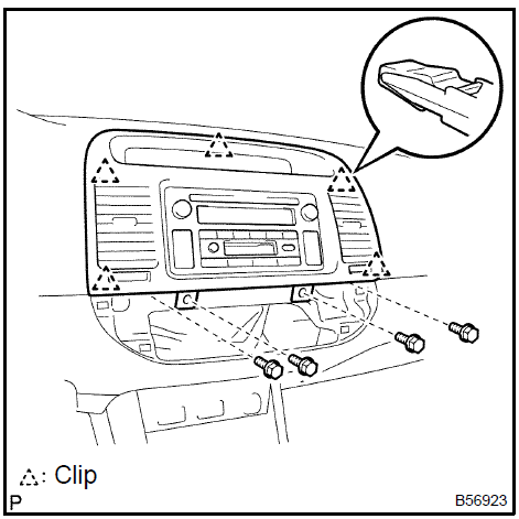 Remove instrument cluster finish panel sub-assy center
23. REMOVE GLOVE COMPARTMENT DOOR PAD
a. Using a screwdriver, remove the glove compartment door pad.
HINT: Tape the screwdriver tip before use.
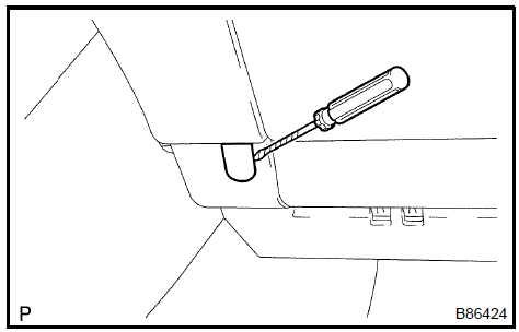 Remove glove compartment door pad
24. REMOVE INSTRUMENT PANEL SUB−ASSY LOWER
- TMC made: Remove the bolt <E> and 4 screws <K>.
- TMMK made: Remove the bolt <D> and 4 screws <H>.
- Disengage the claw and clip and remove the instrument panel sub−assy lower.
 Remove instrument panel sub-assy lower
25. REMOVE SHIFT LEVER KNOB SUB−ASSY (MANUAL TRANSAXLE)
a. Turn the shift lever knob sub−assy counterclockΩise and remove the shift lever knob sub−assy.
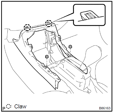
26. REMOVE CONSOLE PANEL UPPER REAR
a. Foot parking brake: Using a moulding remover, disengage the claw and 8 clips and remove the console panel upper rear.
HINT: Set the shift lever in the N position.
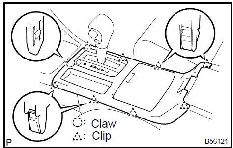 Remove console panel upper rear
b. Hand parking brake: Using a moulding remover, disengage the claw and 8 clips and remove the console panel upper rear.
HINT: Set the shift lever in the N position (Automatic transaxle).
27. REMOVE CONSOLE BOX CARPET 28. REMOVE RR CONSOLE BOX
- TMC made: Remove the 2 bolts <B> and 2 screws <I>.
- TMMK made: Remove the 2 bolts <C> and 2 screws <H>.
- Disengage the 2 claws and remove the RR console box.
 Remove rr console box
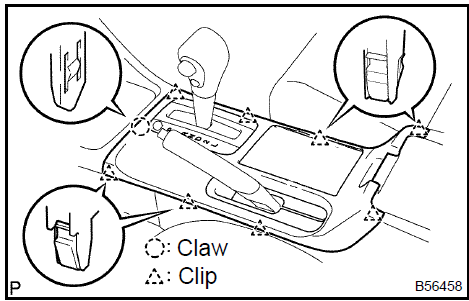
29. REMOVE CONSOLE PANEL SUB−ASSY
- Using a moulding remover, disengage the 4 clips.
- Disconnect the connectors and remove the console panel sub−assy.
HINT: Set the shift lever in the N position (Automatic transaxle).
 Remove console panel sub-assy
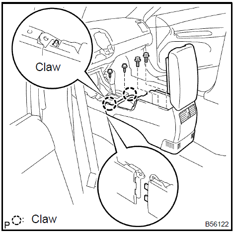
30. REMOVE CONSOLE BOX FRONT
- Remove the 2 nuts <M>.
- Disengage the 2 claws and remove the console box front.
 Remove console box front
31. REMOVE INSTRUMENT PANEL FINISH PANEL LOWER CENTER
- TMC made: Remove the 2 screws <K>.
- TMMK made: Remove the 2 screws <H>.
- Disengage the 4 clips and remove the instrument panel finish panel lower center.
 Remove instrument panel finish panel lower center
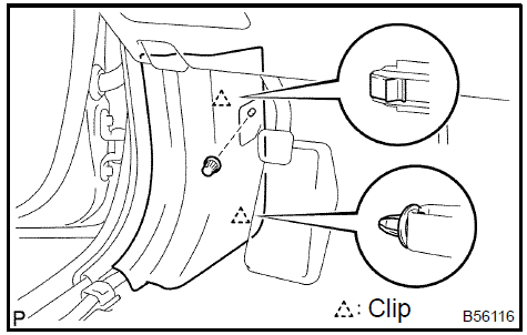
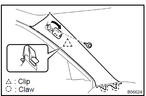
32. REMOVE FRONT PILLAR GARNISH LH (W/O CURTAIN SHIELD AIR BAG)
a. Using a moulding remover, disengage the 2 clips and 2 claws then remove the front pillar garnish LH.
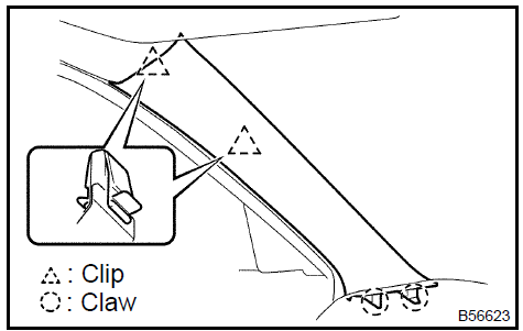 Remove front pillar garnish LH (W/O curtain shield air bag)
33. REMOVE FRONT PILLAR GARNISH LH (W/ CURTAIN SHIELD AIR BAG)
a. Using a screwdriver, open the cover and remove the bolt.
HINT: Tape the screwdriver tip before use.
b. Using a moulding remover, disengage the clip and 2 claws then remove the front pillar garnish LH.
 Remove front pillar garnish LH (W/ curtain shield air bag)
34. REMOVE FRONT PILLAR GARNISH RH (W/O CURTAIN SHIELD AIR BAG)
HINT: Use the same procedures for the RH side and LH side.
35. REMOVE FRONT PILLAR GARNISH RH (W/ CURTAIN SHIELD AIR BAG)
HINT: Use the same procedures for the RH side and LH side.
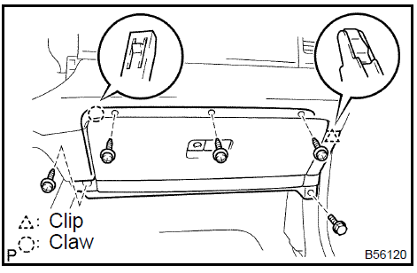
36. REMOVE INSTRUMENT PANEL SPEAKER PANEL SUB−ASSY No.2
a. Using a screwdriver, disengage the 2 clips and 2 claws.
HINT: Tape the screwdriver tip before use.
b. Remove the instrument panel speaker panel sub−assy No.2.
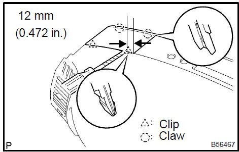 Remove instrument panel speaker panel sub-assy No.2
37. REMOVE INSTRUMENT PANEL SPEAKER PANEL SUB−ASSY
HINT: Use the same procedures for the instrument panel speaker panel sub−assy and instrument panel speaker panel sub−assy No.2.
- REMOVE FRONT No.2 SPEAKER ASSY
- DISCONNECT PASSENGER AIRBAG CONNECTOR
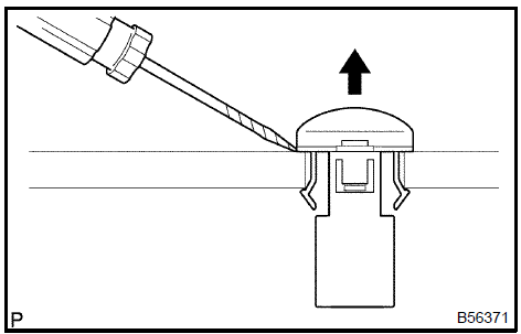
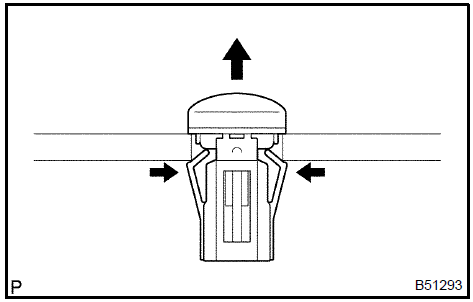
- REMOVE INSTRUMENT PANEL SAFETY PAD CAP
a. Using a screwdriver, remove the instrument panel safety pad cap.
HINT: Tape the screwdriver tip before use.
 Remove instrument panel safety pad cap
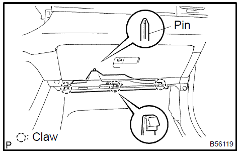
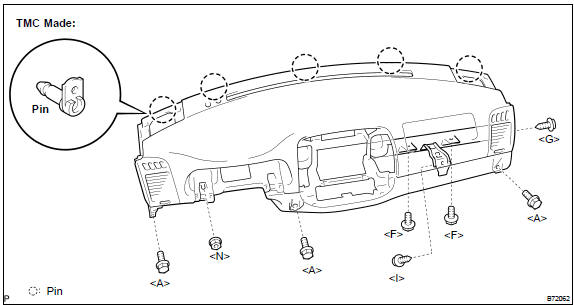
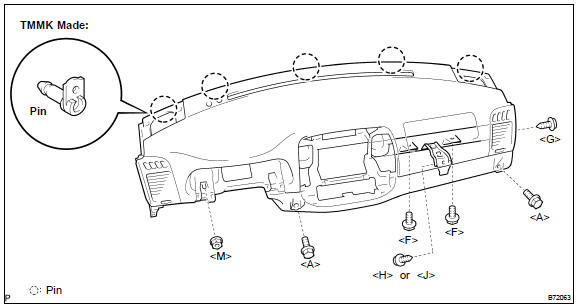
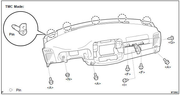
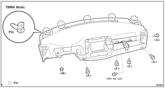
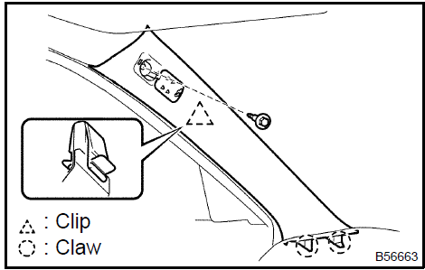
41. REMOVE INSTRUMENT PANEL SAFETY PAD SUB−ASSY W/FRONT PASSENGER AIRBAG
ASSY
- TMC made: Remove the 2 screws <G> <I>, nut <N> and 5 bolts <A> <F>.
- TMMK made: Remove the 2 screws <H> or <J> <G>, nut <M> and 4 bolts <A> <F>.
- Disconnect the connectors.
- Disengage the 5 pins and remove the instrument panel safety pad sub−assy with front passenger airbag assy.
42. REMOVE INSTRUMENT PANEL REGISTER ASSY No.2
- Disengage the 3 clips and 3 claws.
- Remove the instrument panel register assy No.2.
43. REMOVE INSTRUMENT PANEL REGISTER ASSY No.1
- Disengage the 3 clips and 3 claws.
- Remove the instrument panel register assy No.1.
44. REMOVE GLOVE BOX LAMP ASSY
a. Disengage the 4 claws and remove the glove box lamp assy.
45. REMOVE AUTOMATIC LIGHT CONTROL SENSOR
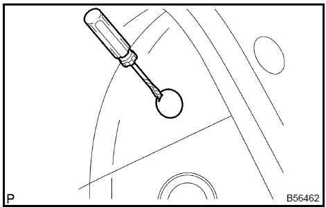
a. Using a screwdriver, remove the automatic light control sensor.
HINT: Tape the screwdriver tip before use.
 Remove automatic light control sensor
46. REMOVE COOLER (SOLAR SENSOR) THERMISTOR (AUTO AIR CONDITIONING)
a. Remove the cooler (solar sensor) thermistor.
NOTICE: Do not pry the cooler (solar sensor) thermistor off from the upper side.
 Remove cooler (solar sensor) thermistor (auto air conditioning)
- REMOVE SPARE SWITCH HOLE COVER (MANUAL AIR CONDITIONING)
- REMOVE SIDE DEFROSTER NOZZLE DUCT No.2
- TMC made: Remove the screw <I> and side defroster nozzle duct No.2.
- TMMK made: Remove the screw <H> or <J> and side defroster nozzle duct No.2.
49. REMOVE SIDE DEFROSTER NOZZLE DUCT No.1
- TMC made: Remove the screw <I> and side defroster nozzle duct No.1.
- TMMK made: Remove the screw <H> or <J> and side defroster nozzle duct No.1.
50. REMOVE DEFROSTER NOZZLE ASSY
- TMC made: Remove the 5 screws <I> and defroster nozzle assy.
- TMMK made: Remove the 5 screws <H> or <J> and defroster nozzle ass
51. REMOVE HEATER TO REGISTER DUCT No.1
- TMC made: Remove the 2 screws <I> and heater to register duct No.1.
- TMMK made: Remove the 2 screws <H> or <J> and heater to register duct No.1.
52. REMOVE HEATER TO REGISTER DUCT No.3
- TMC made: Remove the 2 screws <I> and heater to register duct No.3.
- TMMK made: Remove the 2 screws <H> or <J> and heater to register duct No.3.
53. REMOVE HEATER TO REGISTER DUCT No.2
- TMC made: Remove the screw <I> and heater to register duct No.2.
- TMMK made: Remove the screw <H> or <J> and heater to register duct No.2.
54. REMOVE DEFROSTER NOZZLE GARNISH No.1
a. Disengage the 5 clips and remove the defroster nozzle garnish No.1.
55. REMOVE INSTRUMENT PANEL PIN No.1
- TMC made: Remove the 2 screws <I> and 2 instrument panel pin No.1.
- TMMK made: Remove the 2 screws <H> or <J> and 2 instrument panel pin No.1.
- REMOVE FRONT PASSENGER AIRBAG ASSY
- INSTALL FRONT PASSENGER AIRBAG ASSY
- INSTALL INSTRUMENT PANEL SAFETY PAD SUB−ASSY W/FRONT PASSENGER AIRBAG ASSY
- Engage the 5 pins.
- Connect the connectors.
- TMC made: Install the instrument panel safety pad sub−assy w/ front passenger aibag assy with the 2 screws <G> <I>, nut <N>, and 5 bolts <A> <F>. Torque: Bolt <F> : 20 N·m (204 kgf·cm, 15 ft·lbf)
- TMMK made: Install the instrument panel safety pad sub−assy w/ front passenger airbag assy with the 2 screws <H> or <J> <G>, nut <M>, and 4 bolts <A> <F>. Torque : Bolt <F>: 20 N·m (204 kgf·cm, 15 ft·lbf)
59. INSTALL FRONT PILLAR GARNISH LH (W/ CURTAIN SHIELD AIR BAG)
- Engage the 2 claws and clip.
- Install the front pillar garnish with the bolt.
Torque: 7.5 to 20 N·m (77 to 204 kgf·cm, 67 in.·lbf to 14 ft·lbf)
 Install front pillar garnish LH (W/ curtain shield air bag)
60. INSTALL FRONT PILLAR GARNISH RH (W/ CURTAIN SHIELD AIR BAG)
HINT: Use the same procedures for the RH side and LH side.
- CENTER SPIRAL CABLE
- INSTALL STEERING WHEEL ASSY
- INSTALL HORN BUTTON ASSY
- INSPECT HORN BUTTON ASSY
- INSPECT SRS WARNING LIGHT
Combination meter
Instrument panel safety pad sub-assy
Combination meter assy
Clock assy
Combination meter
Instrument panel/meter
Toyota Camry XV30 (2002–2006) Service Manual
- Introduction
- Audio & visual system
- Automatic transmission / trans
- Brake
- Clutch
- Communication system
- Cooling
- Cruise control
- Drive shaft / propeller shaft
- Emission control
- Engine control system
- Engine hood/door
- Engine mechanical
- Exhaust
- Exterior/interior trim
- Front suspension
- Fuel
- Heater & air conditioner
- Ignition
- Instrument panel/meter
- Intake
- Lighting
- Lubrication
- Manual transmission/transaxle
- Parking brake
- Power steering
- Rear suspension
- Seat
- Service specifications
- Sliding roof/convertible
- Starting & charging
- Steering column
- Supplemental restraint system
- Theft deterrent & door lock
- Tire & wheel
- Windshield/windowglass/mirror
- Wiper & washer
- Wiring
Categories
