 Toyota Camry XV30 (2002–2006) Service ManualIntroduction
Repair instruction
Repair instruction
Repair instruction
PRECAUTION
1. BASIC REPAIR HINT
a. HINTS ON OPERATIONS
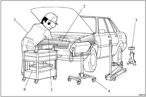 Basic repair hint
b. JACKING UP AND SUPPORTING VEHICLE
1. Care must be taken when jacking up and supporting the vehicle. Be sure to lift and support the vehicle at the proper locations .
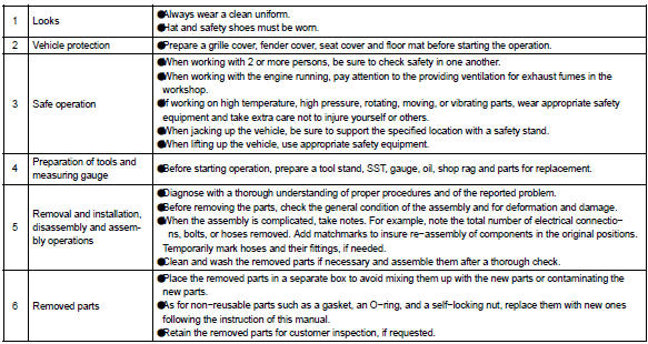
c. PRECOATED PARTS
- Precoated parts are bolts, nuts, etc. that are coated with a seal lock adhesive at the factory.
- If a precoated part is retightened, loosened or moved in anyway, it must be recoated with the specified adhesive.
- When reusing precoated parts, clean off the old adhesive and dry the part with compressed air.
- Then apply new seal lock adhesive appropriate to the bolt, nut, or threads.
NOTICE: Perform the torque with the lower limit value of the torque tolerance.
4. Some seal lock agents harden slowly. You may have to wait for the seal lock agent to harden.
Precoated parts
d. GASKETS
1. When necessary, use a sealer on gaskets to prevent leaks.
e. BOLTS, NUTS AND SCREWS
1. Carefully follow all the specifications for tightening torques. Always use a torque wrench.
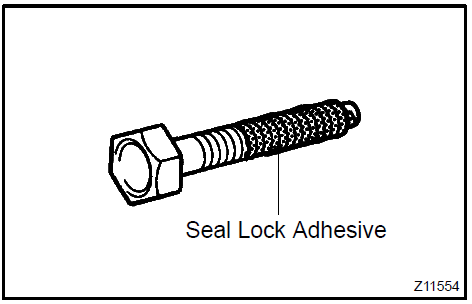
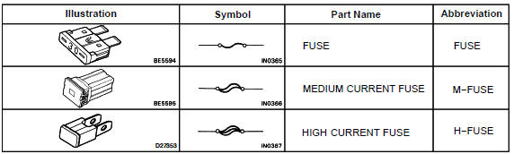
f. FUSES
1. When replacing fuses, be sure that the new fuse has the correct amperage rating. DO NOT exceed the rating or use one with a lower rating.
Fuses
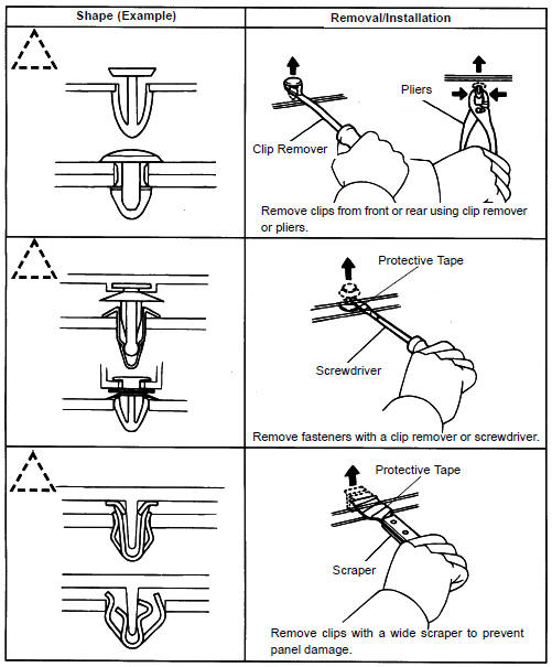
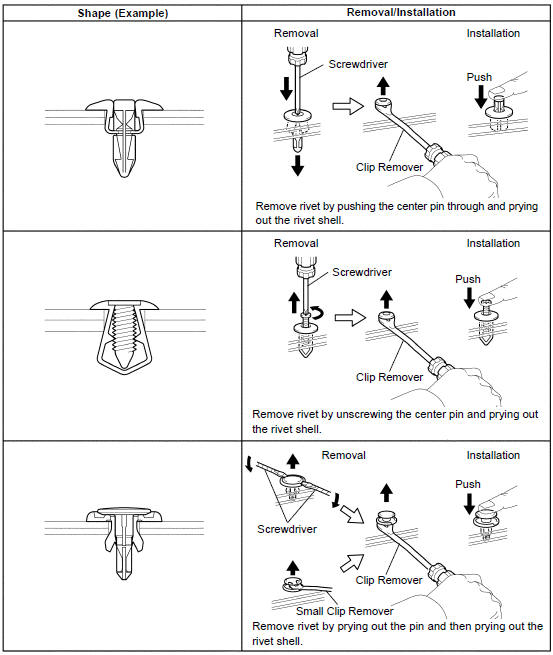
g. CLIPS
1. The removal and installation methods of typical clips used in body parts are shown in the table below.
HINT: If clips are damaged during a procedure, always replace the damaged clip with a new clip.
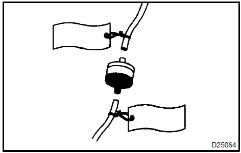
h. REMOVAL AND INSTALLATION OF VACUUM HOSES
1. To disconnect vacuum hose, pull and twist from the end of the hose. Do not pull from the middle of the hose as this may cause damage.
- When disconnecting vacuum hoses, use tags to identify where they should be reconnected.
- After completing the job, double check that the vacuum hoses are properly connected. The label under the hood shows the proper layout.
- When using a vacuum gauge, never force the hose onto a connector that is too large. Use a step−down adapter for adjustment. Once the hose has been stretched, it may leak air.
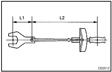
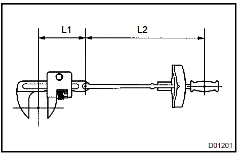
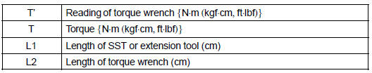
i. TORQUE WHEN USING TORQUE WRENCH WITH EXTENSION TOOL
- If SST or an extension tool is combined with the torque wrench to extend its length, do not tighten the torque wrench to the specified torque values in this manual. The actual torque will be excessive.
- Use the formula below to calculate special torque values for situations where SST or an extension tool is combined with the torque wrench.
- Formula: T’=T x L2/(L1 + L2)
2. FOR VEHICLES EQUIPPED WITH SRS AIRBAG AND SEAT BELT PRETENSIONER
HINT: The CAMRY is equipped with a Supplemental Restraint System (SRS) and seat belt pretensioner.
Failure to carry out the service operations in the correct sequence could cause the SRS to unexpectedly deploy during servicing and lead to serious injury.
Furthermore, if a mistake is made when servicing the SRS, it is possible that the SRS may fail to operate properly. Before servicing (including removal or installation of parts, inspection or replacement), be sure to read the following section carefully.
a GENERAL NOTICE
- Malfunction symptoms of the SRS are difficult to confirm so the Diagnostic Trouble Codes (DTCs) become the most important source of information when troubleshooting. When troubleshooting the SRS, always check the DTCs before disconnecting the battery.
- To avoid serious injury, servicing the SRS must be started 90 seconds after:
- The ignition switch is turned to the LOCK position.
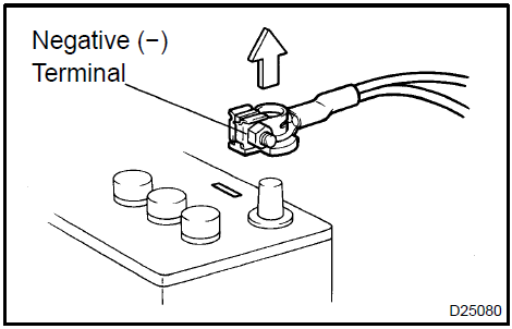
- The negative (−) terminal cable is disconnected from the battery.
(The SRS is equipped with a back−up power source. If work is started within 90 seconds of disconnecting the negative (−) terminal cable from the battery, the SRS may deploy).
Disconnecting the negative (−) terminal cable will erase clock memory and audio system presets.
Mark down data as necessary before disconnecting the cable.
CAUTION: Never use a back−up power source (battery or other) avoid erasing system memory. The back−up power source may power the SRS, leading to a possible SRS and cause it to deploy.
- In minor collisions where the SRS does not deploy, the horn button assembly, instrument panel passenger airbag assembly front seat airbag assembly, curtain shield airbag assembly and seat belt pretensioner should be inspected before further use of the vehicle (See pages 60−27, 60−40, 60−53, 60−47 and 61−7).
- Never use SRS parts from another vehicle. When replacing parts, use new parts.
- (Before repairs, remove the airbag if impacts are likely to be applied to the during repairs.
- Never disassemble and repair the airbag assembly, horn button assembly, instrument panel passenger airbag assembly front seat airbag assembly, curtain shield airbag assembly or seat belt pretensioner.
- Replace the center airbag assembly, side airbag assembly, horn button assembly or the instrument panel passenger airbag assembly front seat airbag assembly or curtain shield airbag assembly: 1) if damage has occurred from being dropped, or 2) if there are cracks, dents or other defects in the case, bracket or connector.
- Do not directly expose the airbag assembly, front seat airbag assembly, curtain shield airbag assembly the horn button assembly, the instrument panel passenger airbag assembly or the seat belt pretensioner to hot air or flames.
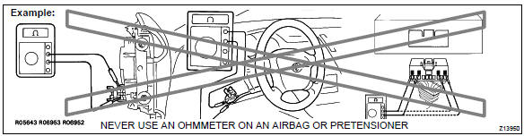
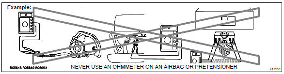
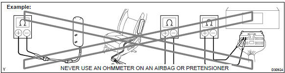
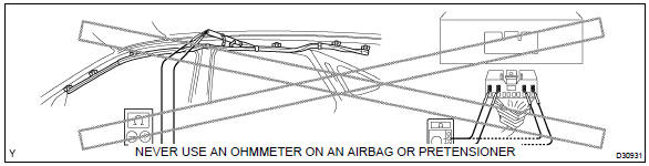
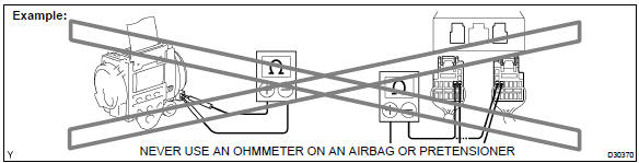
- Use a voltmeter/ohmmeter with high impedance (10 kW/V minimum) for troubleshooting electrical circuits.
- Information labels are attached to the SRS components. Follow the instructions on the labels.
- After work on the SRS is completed, check the SRS warning light .
b. SPIRAL CABLE (in Combination Switch)
1. The steering wheel must be fitted correctly to the steering column with the spiral cable at the neutral position, otherwise cable disconnection and other problems may occur. Refer to page 60−34 concerning the correct installation of the steering wheel.
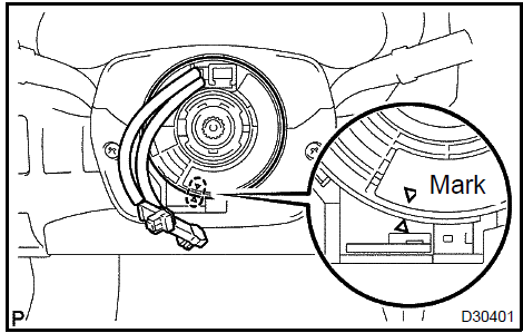
Spiral cable
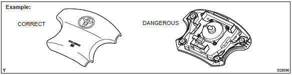
c. HORN BUTTON ASSEMBLY (with Airbag)
- When removing the horn button assembly or handling a new horn button, it
should be placed with
the pad surface facing up. See illustration below.
Placing the horn button with the pad surface facing down may lead to a serious accident if the airbag accidently inflates. Also, do not place anything on top of the horn button.
- Never measure the resistance of the airbag squib. This may cause the airbag to inflate, which could cause serious injury.
- Grease or detergents of any kind should not be applied to the steering wheel pad.
- Store the horn button assembly where the ambient temperature remains below 93°C (200°F), has low humidity and is away from electrical noise.
- When using electric welding anywhere on the vehicle, disconnect the airbag ECU connectors (4 yellow pins). These connectors contain shorting springs. This feature reduces the possibility of the airbag or seat belt pretensioner deploying due to currents entering the squib wiring.
- When disposing of the vehicle or the horn button assembly by itself, the airbag should be inflated using an SST before disposal . Perform the operation in a safe place away from electrical noise.
d. INSTRUMENT PANEL PASSENGER AIRBAG ASSY
- Always place a removed or new instrument panel passenger airbag assembly
with the airbag
inflation direction facing upward.
Placing the airbag assembly with the airbag inflation direction facing downward could cause a serious accident if the airbag inflates.
- Never measure the resistance of the airbag squib. This may cause the airbag to inflate, which could cause serious injury.
- Grease or detergents of any kinds should not be applied to the instrument panel passenger airbag assembly.
- Store the airbag assembly where the ambient temperature remains below 93°C (200°F), has low humidity and away from electrical noise.
- When using electric welding anywhere on the vehicle, disconnect the airbag ECU connectors (4 yellow pins). These connectors contain shorting springs. This feature reduces the possibility of the airbag deploying due to currents entering the squib wiring.
- When disposing of a vehicle or the airbag assembly unit by itself, the
airbag should be deployed
using SST before disposal .
Activate in a safe place away from electrical noise.
e. FRONT SEAT AIRBAG ASSEMBLY
- Always place a removed or new front seat airbag assembly with the airbag inflation direction facing upward. Placing the airbag assembly with the airbag inflation direction facing downward could cause a serious accident if the airbag deploys.
- Never measure the resistance of the airbag squib. This may cause the airbag to inflate, which is very dangerous.
- Grease should not be applied to the front seat airbag assembly, and the airbag door should not be cleaned with detergents of any kind.
- Store the airbag assembly where the ambient temperature remains below 93°C (200°F), without high humidity and away from electrical noise.
- When using electric welding anywhere on the vehicle, disconnect the airbag ECU connectors (2 yellow pins). These connectors contain shorting springs. This feature reduces the possibility of the airbag deploying due to currents entering the squib wiring.
- When disposing of a vehicle or the airbag assembly unit, the airbag
should be deployed using
SST before disposal .
Activate in a safe place away from electrical noise.
f. CURTAIN SHIELD AIRBAG ASSEMBLY
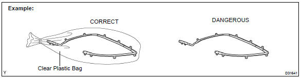
- Always place the removed or new curtain shield airbag assembly in a clear plastic bag, and keep it in a safe place.
NOTICE: Plastic bag is not re−useable.
CAUTION: Never disassemble the curtain shield airbag assembly.
- Never measure the resistance of the airbag squib. This may cause the airbag to inflate, which is very dangerous.
- Grease should not be attached to the curtain shield airbag assembly, and the surface should not be cleared with detergents of any kind.
- Store the airbag assembly where the ambient temperature remains below 93°C (200°F), without high humidity and away from electrical noise.
- When using electric welding anywhere on the vehicle, disconnect the airbag ECU connectors (2 yellow pins). These connectors contain shorting springs. This feature reduces the possibility of the airbag deploying due to currents entering the squib wiring.
- When disposing of a vehicle or the curtain shield airbag assembly unit, the airbag should be deployed using SST before disposal .
- Activate in a safe place away from electrical noise.
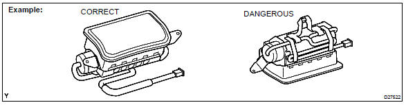
g. SEAT BELT PRETENSIONER
- Never measure the resistance of the seat belt pretensioner (This may cause the seat belt pretensioner to activate, which is very dangerous).
- Never disassemble the seat belt pretensioner.
- Never install the seat belt pretensioner on another vehicle.
- Store the seat belt pretensioner where the ambient temperature remains below 80°C (176°F) without high humidity and away from electrical noise.
- When using electric welding anywhere on the vehicle, disconnect the airbag ECU connectors (2 yellow pins). These connectors contain shorting springs. This feature reduces the possibility of the airbag deploying due to currents entering the squib wiring.
- When disposing of a vehicle or the seat belt pretensioner unit, the seat belt pretensioner should be activated before disposal . Perform the operation in a safe place away from electrical noise.
- The seat belt pretensioner is hot after being activated, so allow some time for it to cool down sufficiently before disposal. Never apply water to cool down the seat belt pretensioner.
- Oil or water should not be put on the front seat outer belt, and the front seat outer belt should not be cleaned with detergents of any kind.
 Seat belt pretensioner
h. AIRBAG ASSEMBLY
- Never reuse an airbag assembly that has been involved in a collision where the SRS has deployed.
- The connectors to the airbag assembly should be connected or disconnected with the mounted on the floor. If the connectors are connected or disconnected while the airbag assembly is not mounted to the floor, it could cause accidental deployment of the SRS.
- Work must be started at last 90 seconds after the ignition switch is turned to the LOCK position and the negative (−) terminal cable is disconnected from the battery, even if only loosening the set bolts of the airbag assembly.
i. WIRE HARNESS AND CONNECTOR
1. The SRS wire harness is integrated with the instrument panel wire harness assembly. All the connectors in the system are a standard yellow color. If the SRS wire harness becomes disconnected or the connector becomes broken, repair or replace it.
3. ELECTRONIC CONTROL
a. REMOVAL AND INSTALLATION OF BATTERY TERMINAL
- Before performing electronic work, disconnect the battery negative (−) terminal cable beforehand to prevent component and wire damage caused by accidental short circuits.
- When disconnecting and installing the terminal cable, turn the ignition switch and lighting switch OFF and loosen the terminal nut completely. Perform these operations without twisting or prying the terminal. Remove the battery cable from battery post.
- Clock settings, radio settings, DTCs and other data are erased when the battery cable is removed. Before removing the battery cable, record any necessary data.
- When disconnecting the battery’s negative (−) terminal cable, re−initialize the following systems after the completion of the operation.
Removal and installation of battery terminal
b. HANDLING OF ELECTRONIC PARTS
- Do not open the cover or case of the ECU unless absolutely necessary. If the IC terminals are touched, the IC may be rendered inoperative by static electricity.
- To disconnect electronic connectors, pull the connector itself, not the wires.
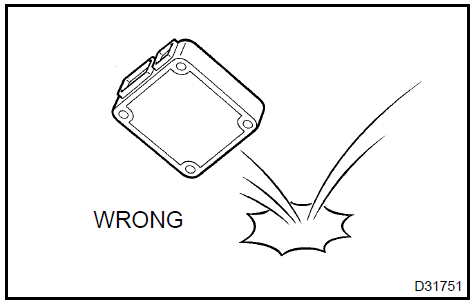
- Be careful not to drop electronic components, such as s or relays. If they are dropped on a hard floor, they should be replaced.
- When cleaning the engine with steam, protect the electronic components, air filter and emission−related components from water.
- Never use an impact wrench to remove or install temperature switches or temperature s.
- When checking the continuity at the wire connector, insert the tester probe carefully to prevent terminals from bending.
Handling of electronic parts
4. REMOVAL AND INSTALLATION OF FUEL CONTROL PARTS
a. PLACE FOR REMOVING AND INSTALLING OF FUEL SYSTEM PARTS
- Work in a place with good air ventilation and without any ignition sources, such as a welder, grinder, drill, electric motor or stove.
- Never work in a place such as a pit or near a pit because vaporized fuel will collect in those places.
b. REMOVING AND INSTALLING OF FUEL SYSTEM PARTS
- Prepare a fire extinguisher before starting operation.
- To prevent static electricity, install a ground on the fuel changer, vehicle and fuel tank, and do not spray the area with water. The work surface will become slippery. Do not clean up spills with water as this will spread and gasoline and create a fire hazard.
- Never use any electric equipment like an electric motor or a working light, as they may create sparks or high temperatures.
- Never use an iron hammer, as it may create sparks.
- Dispose of fuel−contaminated shop rags separately using a fire restraint container.
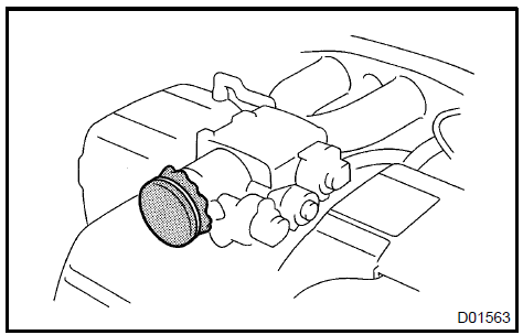
5. REMOVAL AND INSTALLATION OF ENGINE INTAKE PARTS
- If any metal particle enters the inlet pass, this may damage the engine.
- When removing and installing the inlet system parts, cover the openings of the removed parts and engine openings.
- Use clean shop rags, gummed tape, or other suitable materials.
- When installing the inlet system parts, check that no metal particles have entered the engine or the installed part.
Removal and installation of engine intake parts
6. HANDLING OF HOSE CLAMPS
- Before removing the hose, check the clamp position so that you can restore it in the same way.
- Replace deformed or dented clamps with a new one.
- When reusing a hose, attach the clamp on the clamp track portion of the hose.
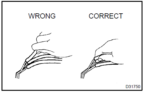
- For a spring type clamp, you may want to spread the tabs slightly after installation by pushing in the direction of the arrow marks as shown in the illustration.
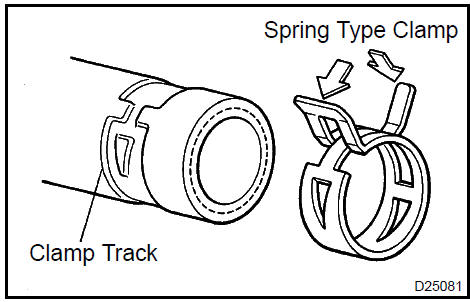
Handling of hose clamps
7. FOR VEHICLES EQUIPPED WITH MOBILE COMMUNICATION SYSTEMS
- Install the antenna as far away from the ECU and s of the vehicle electronic systems as possible.
- Install an antenna feeder at least 20 cm (7.87 in.) away from the ECU and s of the vehicle electronic systems. For details of the ECU and s locations, refer to the section on applicable components.
- Keep the antenna and feeder separate from other wirings as much as possible. This will prevent signals from the communication equipment from affecting vehicle equipment and vice−versa.
- Check that the antenna and feeder are correctly adjusted.
- Do not install any high−powered mobile communication system.
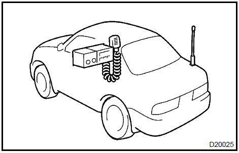
For vehicles equipped with mobile communication systems
8. FOR VEHICLES EQUIPPED WITH TRACTION CONTROL (TRAC) SYSTEM
When using a 2−wheel drum tester such as a speedometer tester, a combination tester of speedometer and brake, chassis dynamometer, or jacking up the front wheels and driving the wheels, always turn the TRAC system off via the TRAC OFF switch before testing.
NOTICE: TRAC system OFF condition can be confirmed by the ”TRAC OFF” warning indicator light in the combination meter.
a. Confirm TRAC system is OFF
- Press the TRAC cut (”TRAC OFF”) switch to turn off the TRAC system.
- Check if the TRAC OFF indicator light illuminates.
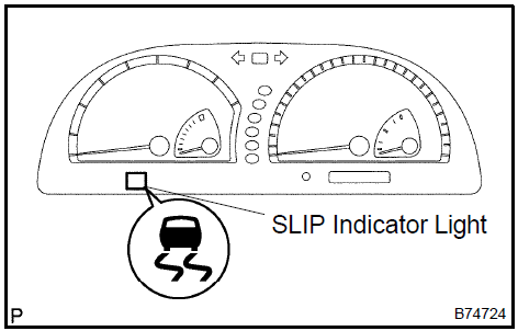
HINT: The SLIP indicator light should always operate right after the engine is restarted.
- Begin testing.
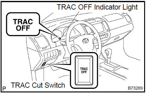
- Press the TRAC cut switch to turn on the TRAC system and check that the TRAC OFF indicator light turns off.
HINT: The SLIP indicator light blinks when the TRAC system is operating.
9. FOR VEHICLES EQUIPPED WITH VEHICLE SKID CONTROL (VSC) SYSTEM
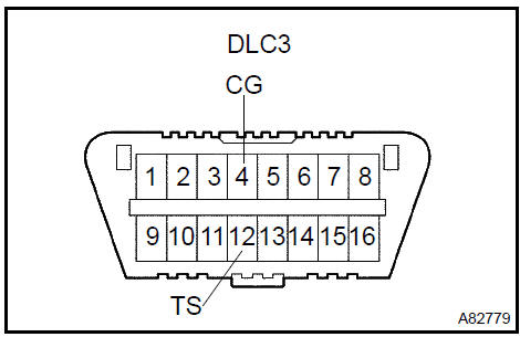
a. NOTICES WHEN USING DRUM TESTER
- Before beginning testing, disable the Vehicle Skid Control system (VSC). To disable the VSC, turn the ignition switch OFF and connect SST to terminals TS and CG of DLC3.
For vehicles equipped with vehicle skid control (VSC) system
NOTICE:
- Confirm that the VSC warning light blinks.
- VSC system will be reset when the engine is restarted.
- For safety, secure the vehicle with restraint chains while using a wheel dynamometer.
b. NOTICES OF RELATED OPERATIONS TO VSC
- Do not carry out unnecessary installation and removal as it might affect the adjustment of VSC related parts.
- Be sure to follow the instructions for work preparation and final confirmation of proper operation of the VSC system.
10. FOR VEHICLES EQUIPPED WITH CATALYTIC CONVERTER
CAUTION: If a large amount of unburned gasoline or gasoline vapors flow into the converter, it may cause overheat and create a fire hazard. To prevent this, observe the following precautions.
- Use only unleaded gasoline.
- Avoid prolonged idling. Avoid idling the engine for more than 20 minutes.
- Avoid a spark jump test.
- Perform a spark jump test only when absolutely necessary. Perform this test as rapidly as possible.
- While testing, never race the engine.
- Avoid a prolonged engine compression measurement. Engine compression measurements must be performed as rapidly as possible.
- Do not run the engine when the fuel tank is nearly empty. This may cause the engine to misfire and create an extra load on the converter.
How to use this manual
Repair instruction
How to troubleshoot ecu controlled systems
Identification information
Terms
Repair instruction
Toyota Camry XV30 (2002–2006) Service Manual
- Introduction
- Audio & visual system
- Automatic transmission / trans
- Brake
- Clutch
- Communication system
- Cooling
- Cruise control
- Drive shaft / propeller shaft
- Emission control
- Engine control system
- Engine hood/door
- Engine mechanical
- Exhaust
- Exterior/interior trim
- Front suspension
- Fuel
- Heater & air conditioner
- Ignition
- Instrument panel/meter
- Intake
- Lighting
- Lubrication
- Manual transmission/transaxle
- Parking brake
- Power steering
- Rear suspension
- Seat
- Service specifications
- Sliding roof/convertible
- Starting & charging
- Steering column
- Supplemental restraint system
- Theft deterrent & door lock
- Tire & wheel
- Windshield/windowglass/mirror
- Wiper & washer
- Wiring
Categories
