 Toyota Camry XV30 (2002–2006) Service ManualStarting & charging
Starter assy (2AZ−FE)(From July, 2003)
Starter assy (2AZ−FE)(From July, 2003)
REPLACEMENT
NOTICE:
Before changing the starter, check these items again:
-
Connector connection
-
Accessory installation
-
REMOVE BATTERY
-
REMOVE BATTERY TRAY
-
REMOVE AIR CLEANER ASSY
-
REMOVE AIR CLEANER BRACKET
a. Remove the 2 bolts and air cleaner bracket.
 Remove air cleaner bracket
5. REMOVE AIR CLEANER INLET ASSY
a. Remove the 2 bolts and air cleaner inlet.
6. REMOVE STARTER ASSY
-
Disconnect the starter connector.
-
Remove the nut and disconnect the starter wire.
-
Remove the 2 bolts and starter.
7. INSTALL STARTER ASSY
-
Install the and starter with the 2 bolts.
Torque: 39 N·m (398 kgf·cm, 29 ft·lbf)
-
Install the starter wire and the nut.
Torque: 13 N·m (130 kgf·cm, 9 ft·lbf)
-
Connect the starter connector.
8. INSTALL AIR CLEANER BRACKET
a. Install the air cleaner bracket with the 2 bolts.
Torque: 12 N·m (122 kgf·cm, 9 ft·lbf)
-
INSTALL AIR CLEANER ASSY Torque: 5.0 N·m (51 kgf·cm, 44 in.·lbf)
-
INSTALL AIR CLEANER INLET ASSY
a. Install the air cleaner inlet with the 2 bolts.
Torque: 7.0 N·m (71 kgf·cm, 62 in.·lbf)
-
CHECK CONNECTION OF VACUUM HOSE
-
INSTALL BATTERY TRAY
-
INSTALL BATTERY
-
Install the battery clamp with the bolt and nut.
Torque: 5.5 N·m (56 kgf·cm, 49 inVlbf)
-
Connect the wires to the battery terminals.
Torque: 3.5 N·m (36 kgf·cm, 31 in.·lbf)
OVERHAUL
1. REMOVE MAGNETIC SWITCH ASSY
a. Remove the nut and disconnect the lead wire from the magnetic switch.
-
Remove the 2 screws holding the magnetic switch to the starter drive housing.
-
Remove the magnetic switch.
-
Remove the return spring and plunger from starter drive housin
2. REMOVE STARTER FIELD FRAME ASSY
a. Remove the 2 through−bolts, and pull out the field frame together with the commutator end frame assy.
b. Remove the field frame from the commutator end frame.
3. REMOVE STARTER AMATURE PLATE
a. Remove the armature plate from the field frame.
 Remove starter amature plate
4. REMOVE STARTER COMMUTATOR END FRAME COVER
a. Using a screwdriver, remove the commutator end frame cover.
 Remove starter commutator end frame cover
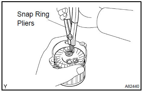
5. REMOVE STARTER ARMATURE ASSY
-
Using snap ring pliers, remove the snap ring and plate washer.
-
Remove the armature from the commutator end frame.
 Remove starter armature assy
6. REMOVE PLANETARY GEAR
a. Remove the 3 planetary gears from the starter drive housing assy.
 Remove planetary gear
7. INSPECT MAGNETIC SWITCH ASSY
a. Check the plunger.
1. Push in the plunger and check that it returns quickly to its original position.
If necessary, replace the magnetic switch.
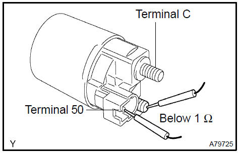
b. Check if the pull−in coil has an open circuit.
1. Check the resistance between terminals 50 and C.
Standard: Below 1 Ω
If the the result is not as specified, replace the magnetic switch.
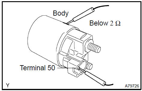
c. Check if the hold−in coil has an open circuit.
1. Check the resistance between terminal 50 and the switch body.
Standard: Below 2 Ω
If the the result is not as specified, replace the magnetic switch.
8. INSPECT STARTER ARMATURE ASSY
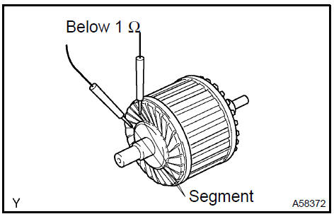
a. Check if the commutator has an open circuit.
1. Check the resistance between the segments of the commutator.
Standard: Below 1 Ω
If the result is not as specified, replace the armature assy.
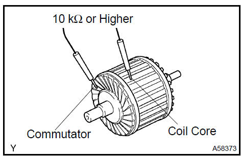
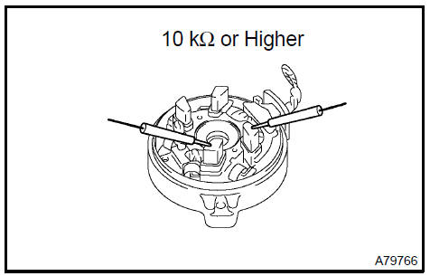
b. Check if the commutator is grounded.
1. Check the resistance between the commutator and armature coil core.
Standard: 10 kΩ or higher
If the result is not as specified, replace the armature assy.
c. Check the commutator for contamination and burns on its surface.
If the surface is dirty or burnt, correct it with sandpaper (No.400) or a lathe.
d. Using a vernier caliper, measure the commutator’s length.
Specified length: 3.1 to 3.8 mm (0.122 to 0.150 in.)
If the length is greater than the maximum, replace the starter armature.
9. INSPECT STARTER COMMUTATOR END FRAME COVER
a. Using a vernier caliper, measure the brush length.
Specified length: 4.0 to 9.0 mm (0.158 to 0.359 in.)
If the length is less than the minimum, replace the end frame assy.
b. Check the brush insulation.
1. Check the resistance between the positive (+) and negative (−) brush.
Standard: 10 kW or higher
If the result is not as specified, repair or replace the end frame assy.
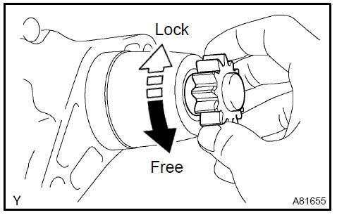
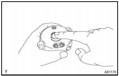
10. INSPECT AND ADJUST CLUTCH & BEARING CENTER
a. Check the starter clutch.
1. Rotate the clutch pinion gear counterclockwise and check that it turns freely. Try to rotate the clutch pinion gear clockwise and check that it locks.
If necessary, replace the clutch & bearing center.
 Inspect and adjust clutch & bearing center
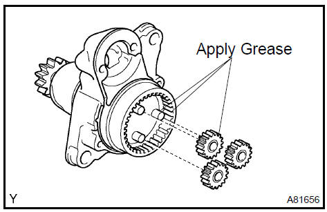
11. INSTALL PLANETARY GEAR
-
Apply grease to the planet gears and pin parts of the planetary shaft.
-
Install the 3 planetary gears.
 Install planetary gear
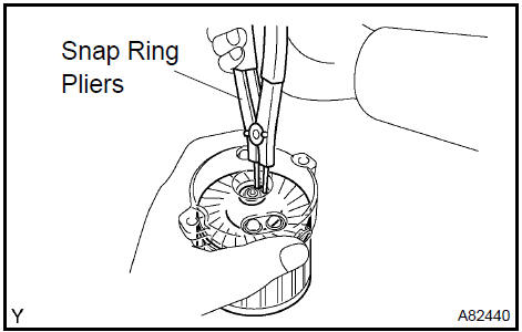
12. INSTALL STARTER ARMATURE ASSY
-
Apply grease to the plate washer and the armature shaft.
-
Install the starter armature to the starter commutator end frame.
-
Using snap ring pliers, install the plate washer and a new snap ring.
d. Using a vernier caliper, measure length of the snap ring.
Maximum length: 5.0 mm (0.197 in.)
If the length is greater than the maximum, replace it with a new snap ring.
13. INSTALL STARTER COMMUTATOR END FRAME COVER
a. Install the end frame cover to the commutator end frame.
 Install starter commutator end frame cover
14. INSTALL STARTER AMATURE PLATE
-
Insert the armature plate to the starter field frame.
-
Align the keyway of the starter plate with the key inside the starter field frame, and install the starter plate.
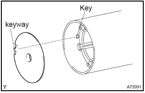 Install starter amature plate
15. INSTALL STARTER COMMUTATOR END FRAME ASSY
-
Align the rubber of the end frame with the cutout of the field frame.
-
Install the end frame to the field frame.
 Install starter commutator end frame assy
16. INSTALL STARTER FIELD FRAME ASSY
a. Align the protrusion of the starter field frame with the cut out of the starter drive housing.
b. Install the field frame with the 2 through bolts.
Torque: 6.0 N·m (61 kgf·cm, 53 in.·lbf)

17. INSTALL MAGNETIC SWITCH ASSY
-
Apply grease to the plunger and the hook.
-
Hang the plunger hook of the magnetic switch to the drive lever.
-
Install the plunger and the return spring.
d. Install the magnetic switch with the 2 screws.
Torque: 7.5 N·m (76 kgf·cm, 66 in.·lbf)
e. Connect the lead wire to the magnetic switch with the nut.
Torque: 10 N·m (102 kgf·cm, 7 ft·lbf)
Starting system (2AZ−FE)(From July, 2003)
Charging system (2AZ−FE)(From July, 2003)
Generator assy (2AZ−FE)(From July, 2003)
Starting system (1MZ−FE/3MZ−FE)
Ignition or starter switch assy (1MZ−FE/3MZ−FE)
Starter assy (1MZ−FE/3MZ−FE)
Ignition or starter switch assy (2AZ−FE)(From July, 2003)
Starter assy (1MZ−FE/3MZ−FE)
Charging system (1MZ−FE/3MZ−FE)
Starter assy (2AZ−FE)(From July, 2003)
Generator assy (1MZ−FE/3MZ−FE)
Starter assy (2AZ−FE)(From July, 2003)
Toyota Camry XV30 (2002–2006) Service Manual
- Introduction
- Audio & visual system
- Automatic transmission / trans
- Brake
- Clutch
- Communication system
- Cooling
- Cruise control
- Drive shaft / propeller shaft
- Emission control
- Engine control system
- Engine hood/door
- Engine mechanical
- Exhaust
- Exterior/interior trim
- Front suspension
- Fuel
- Heater & air conditioner
- Ignition
- Instrument panel/meter
- Intake
- Lighting
- Lubrication
- Manual transmission/transaxle
- Parking brake
- Power steering
- Rear suspension
- Seat
- Service specifications
- Sliding roof/convertible
- Starting & charging
- Steering column
- Supplemental restraint system
- Theft deterrent & door lock
- Tire & wheel
- Windshield/windowglass/mirror
- Wiper & washer
- Wiring
Categories
