 Toyota Camry XV30 (2002–2006) Service ManualSteering column
Steering column assy (TMMK MADE)
Steering column assy (TMMK MADE)
OVERHAUL
-
PRECAUTION
-
SEPARATE BATTERY NEGATIVE TERMINAL
-
REMOVE STEERING WHEEL COVER LOWER No.2
-
REMOVE STEERING WHEEL COVER LOWER No.3 (W/O STEERING PAD SWITCH 4 SPOKE STEERING WHEEL)
-
REMOVE CONNECTOR COVER (W/ STEERING PAD SWITCH 4 SPOKE STEERING WHEEL)
-
REMOVE STEERING WHEEL COVER LOWER No.3 (3 SPOKE STEERING WHEEL ASSY)
-
PLACE FRONT WHEELS FACING STRAIGHT AHEAD
-
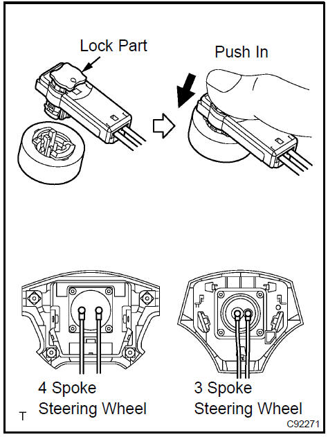
REMOVE HORN BUTTON ASSY
NOTICE: If the airbag connector is disconnected with the ignition switch at ON, DTCs will be recorded.
-
Using a torx) socket wrench, loosen the 2 torx) screws until the groove along the screw circumference catches on the screw case.
-
Pull out the horn button assy from the steering wheel.
-
Using a screwdriver, release the lock part of each airbag connector and disconnect the 2 airbag connectors.
-
Disconnect the horn connector. (4 Spoke steering wheel)
NOTICE: When removing the horn button assy, take care not to pull the airbag wire harness.
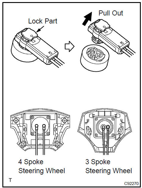
CAUTION: When storing the horn button assy, keep the upper surface of the pad facing upward.
Never disassemble the horn button assy.
9. REMOVE STEERING WHEEL ASSY
SST 09950−50013 (09951−05010, 09952−05010, 09953−05020, 09954−05021)
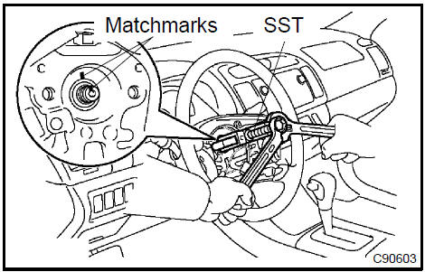 Remove steering wheel assy
-
REMOVE INSTRUMENT CLUSTER FINISH PANEL ASSY
-
REMOVE STEERING COLUMN COVER LWR
a. Remove the 2 screws and steering column cover upper.
 Remove steering column cover LWR
-
REMOVE STEERING COLUMN COVER UPR
-
DISCONNECT FLOOR SHIFT PARKING LOCK CABLE ASSY
a. Using a screwdriver, disconnect the floor shift parking lock cable from the upper bracket.
 Disconnect floor shift parking lock cable assy
-
REMOVE SPIRAL CABLE SUB−ASSY
-
REMOVE HEADLAMP DIMMER SWITCH ASSY
a. Disconnect the connector and remove the headlamp dimmer switch assy.
16. REMOVE WINDSHIELD WIPER SWITCH ASSY
a. Disconnect the connector and remove the windshield wiper switch assy.
-
REMOVE FRONT DOOR SCUFF PLATE LH
-
REMOVE COWL SIDE TRIM SUB−ASSY LH
-
REMOVE INSTRUMENT PANEL FINISH LOWER PANEL LH
-
REMOVE INSTRUMENT PNL INSERT SUB−ASSY LWR LH
-
REMOVE HEATER TO FOOT DUCT No.3
-
DISCONNECT STEERING INTERMEDIATE SHAFT ASSY
-
Loosen the bolt A and remove the clamp from the steering column hole cover No.1.
-
Separate the steering column hole cover No.2 from the steering column hole cover No.1.
-
Loosen the bolt B.
-
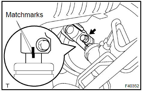
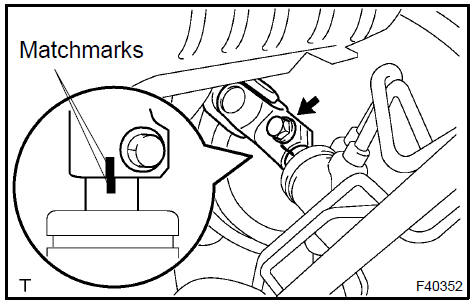
Place matchmarks on the steering intermediate shaft sub−assy and steering gear assy.
-
Remove the bolt and disconnect the steering intermediate shaft sub−assy.
23. REMOVE STEERING COLUMN ASSY
-
Disconnect the connectors and wire harness clamps from the steering column assy.
-
Remove the 3 bolts and steering column assy.
 Remove steering column assy
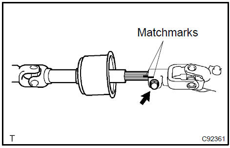
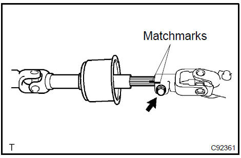
24. REMOVE STEERING INTERMEDIATE SHAFT ASSY
-
Place matchmarks on the steering intermediate shaft sub−assy and steering sliding yoke sub−assy.
-
Remove the bolt and steering intermediate shaft sub− assy.
 Remove steering intermediate shaft assy
25. REMOVE TRANSPONDER KEY AMPLIFIER (W/ ENGINE IMMOBILISER SYSTEM)
-
Disengage the claw hung on the upper bracket with a screwdriver.
-
Pull the transponder key amplifier toward the rear of the vehicle with the claw open.
NOTICE: Take care not to apply excessive force to prevent the case from being damaged.
 Remove transponder key amplifier (W/engine immobiliser system)
-
REMOVE KEY CYLINDER LAMP ASSY (W/ ILLUMINATED ENTRY SYSTEM)
-
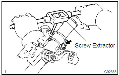
REMOVE STEERING COLUMN UPPER W/SWITCH BRACKET ASSY
-
Using a centering punch, mark the center of the 2 tapered− head bolts.
-
Using a 3 − 4 mm (0.12 − 0.16 in.) drill, drill into the 2 bolts.
-
Using a screw extractor, remove the 2 bolts and steering column upper w/ switch bracket assy.
 Remove steering column upper W/switch bracket assy
-
REMOVE STEERING COLUMN CLAMP UPPER
-
REMOVE IGNITION SWITCH LOCK CYLINDER ASSY
-
Place the ignition switch lock cylinder assy at the ACC position.
-
Push down the stop pin with a screwdriver, and pull out the cylinder assy.
 Remove ignition switch lock cylinder assy
30. REMOVE UN−LOCK WARNING SWITCH ASSY
-
Disconnect the un−lock warning switch assy connector from the ignition or starter switch assy.
-
Remove the un−lock warning switch assy.
 Remove un-lock warning switch assy
31. REMOVE IGNITION OR STARTER SWITCH ASSY
a. Remove the 2 screws and ignition or starter switch assy from the steering column bracket assy.
32. INSTALL IGNITION OR STARTER SWITCH ASSY
a. Install the ignition or starter switch assy to the steering column bracket assy with the 2 screws.
33. INSTALL UN−LOCK WARNING SWITCH ASSY
-
Install the un−lock warning switch assy.
-
Connect the un−lock warning switch assy connector to the ignition or starter switch assy.
 Install un-lock warning switch assy
34. INSTALL IGNITION SWITCH LOCK CYLINDER ASSY
-
Make sure that the ignition switch lock cylinder assy is at the ACC position.
-
Install the ignition switch lock cylinder assy.
35. INSPECT STEERING LOCK OPERATION
-
Check that the steering lock mechanism is activated when removing the key.
-
Check that the steering lock mechanism is deactivated when inserting the key and turning it to ACC position.
36. INSTALL STEERING COLUMN UPPER W/SWITCH BRACKET ASSY
-
Temporarily install the steering column upper w/switch bracket assy and steering column upper clamp with 2 new tapered−head bolts.
-
Tighten the 2 tapered−head bolts until the bolt heads break off.
 Install steering column upper W/switch bracket assy
-
INSTALL KEY CYLINDER LAMP ASSY (W/ ILLUMINATED ENTRY SYSTEM)
-
INSTALL TRANSPONDER KEY AMPLIFIER (W/ ENGINE IMMOBILISER SYSTEM)
-
Align the transponder key amplifier with the installation position of the upper bracket with the amplifier inclined.
-
Push the trasponder key amplifier up and connect it to the upper bracket.
NOTICE: Take care not to push the amplifier up with excessive force to prevent it from being damaged.
 Install transponder key amplifier (W/engine immobiliser system)
39. INSPECT STEERING COLUMN ASSY
a. Measure the length of steering main shaft.
Standard length: 474.5 ± 1 mm (18.681 ± 0.039 in.
)
 Nspect steering column assy
40. INSTALL STEERING INTERMEDIATE SHAFT ASSY
-
Align the matchmark with the one on the steering intermediate shaft sub−assy and steering main shaft assy.
-
Temporarily install the steering intermediate shaft sub− assy with the bolt.
 Install steering intermediate shaft assy
41. INSTALL STEERING COLUMN ASSY
-
Install the steering column assy with the 3 bolts.
Torque: 20.6 N·m (210 kgf·cm, 15 ft·lbf)
-
Connect the connectors and wire harness clamps.
 Install steering column assy
42. CONNECT STEERING INTERMEDIATE SHAFT ASSY
-
Align the matchmarks on the intermediate shaft sub−assy and steering gear assy.
-
Install the steering intermediate shaft sub−assy with the bolt.
Torque: 35.3 N·m (360 kgf·cm, 26 ft·lbf)
-
Tighten the bolt A.
Torque: 35.3 N·m (360 kgf·cm, 26 ft·lbf)
-
Install the steering column hole cover No. 2 to the steering hole cover No.1.
-
Connect the clamp to the steering column hole cover No.1 and tighten the bolt B.
43. INSTALL HEADLAMP DIMMER SWITCH ASSY
a. Install the windshield wiper switch assy and connect the connector.
44. INSTALL WINDSHIELD WIPER SWITCH ASSY
a. Install the headlamp dimmer switch assy and connect the connector.
-
PLACE FRONT WHEELS FACING STRAIGHT AHEAD
-
INSTALL SPIRAL CABLE SUB−ASSY
-
CONNECT FLOOR SHIFT PARKING LOCK CABLE ASSY
-
Turn the ignition switch to ACC or ON.
-
Connect the cable to the upper bracket.
 Connect floor shift parking lock cable assy
-
CHECK KEY INTERLOCK OPERATION
-
INSTALL STEERING COLUMN COVER UPR
-
INSTALL STEERING COLUMN COVER LWR
a. Install the steering column cover with the 2 screws.
 Install steering column cover LWR
-
INSTALL INSTRUMENT CLUSTER FINISH PANEL ASSY
-
INSTALL HEATER TO FOOT DUCT No.3
-
INSTALL INSTRUMENT PNL INSERT SUB−ASSY LWR LH
-
INSTALL INSTRUMENT PANEL FINISH LOWER PANEL LH
-
INSTALL COWL SIDE TRIM SUB−ASSY LH
-
INSTALL FRONT DOOR SCUFF PLATE LH
-
CENTER SPIRAL CABLE
-
Check that the ignition switch is to OFF.
-
Check that the battery negative terminal is disconnected.
NOTICE: Do not start the operation for 90 seconds after removing the terminal.
c. Turn the cable counterclockwise by hand until it becomes harder to turn.
d. Then rotate the cable clockwise about 2.5 turns to align the marks.
HINT: The cable will rotate about 2.5 turns to both right and left of the center.
58. INSTALL STEERING WHEEL ASSY
-
Align the matchmark with the one on the steering wheel assy and steering main shaft assy.
-
Install the steering wheel assy with the set nut.
Torque: 50 N·m (510 kgf·cm, 37 ft·lbf)
-
Connect the connector.
-
INSPECT HORN BUTTON ASSY
-
INSTALL HORN BUTTON ASSY
NOTICE:
-
Never use the airbag parts removed from another vehicle.
When replacing parts, replace with new ones.
-
Make sure that the horn button assy is installed with the specified torque.
-
If the horn button assy has been dropped, or there are cracks, dents or other defects in the case or connector, replace the horn button assy with a new one.
-
When installing the horn button assy, take care so that the wirings do not interfere with other parts and that they are not pinched between other parts.
-
Connect the 2 airbag connectors.
-
Connect the horn connector. (4 Spoke steering wheel)
-
Install the horn button assy after confirming that the circumference groove of the torx) screws is caught on the screw case.
-
Using a torx) socket wrench, torque the 2 screws.
Torque: 8.8 N·m (90 kgf·cm, 78 in.·lbf)
-
INSTALL STEERING WHEEL COVER LOWER No.2
-
INSTALL STEERING WHEEL COVER LOWER No.3 (W/O STEERING PAD SWITCH 4 SPOKE STEERING WHEEL)(
-
INSTALL CONNECTOR COVER (W/ STEERING PAD SWITCH 4 SPOKE STEERING WHEEL)
-
INSTALL STEERING WHEEL COVER LOWER No.3 (3 SPOKE STEERING WHEEL ASSY)
-
INSPECT STEERING WHEEL CENTER POINT
-
INSPECT SRS WARNING LIGHT
Steering
Steering column assy (TMMK MADE)
Steering
Steering column
Steering column assy (TMC MADE)
Toyota Camry XV30 (2002–2006) Service Manual
- Introduction
- Audio & visual system
- Automatic transmission / trans
- Brake
- Clutch
- Communication system
- Cooling
- Cruise control
- Drive shaft / propeller shaft
- Emission control
- Engine control system
- Engine hood/door
- Engine mechanical
- Exhaust
- Exterior/interior trim
- Front suspension
- Fuel
- Heater & air conditioner
- Ignition
- Instrument panel/meter
- Intake
- Lighting
- Lubrication
- Manual transmission/transaxle
- Parking brake
- Power steering
- Rear suspension
- Seat
- Service specifications
- Sliding roof/convertible
- Starting & charging
- Steering column
- Supplemental restraint system
- Theft deterrent & door lock
- Tire & wheel
- Windshield/windowglass/mirror
- Wiper & washer
- Wiring
Categories
