 Toyota Camry XV30 (2002–2006) Service ManualEmission control
Emission control system (1MZ−FE/3MZ−FE)
Emission control system (1MZ−FE/3MZ−FE)
ON−VEHICLE INSPECTION
1. INSPECT AIR−FUEL RATIO COMPENSATION SYSTEM
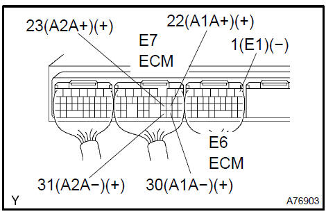
a. Measure the voltage between the terminals of the ECM connectors.
Standard:
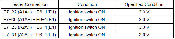
NOTICE: Connect test leads to the connector’s backside. The connectors should not be disconnected from the ECM.
HINT: Voltage between the terminals of the engine ECM is kept constant regardless of the voltage of the A/F .
-
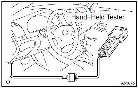
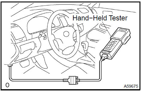
Connect the hand−held tester to the DLC3.
-
Select ”DATA MONITOR”. Then select ”A/FS B1 S1”, ”A/FS B2 S1” and ”O2S B1 S2” to display the monitors.
-
Warm up the A/F with the engine speed at 2,500 rpm for approximately 2 minutes.
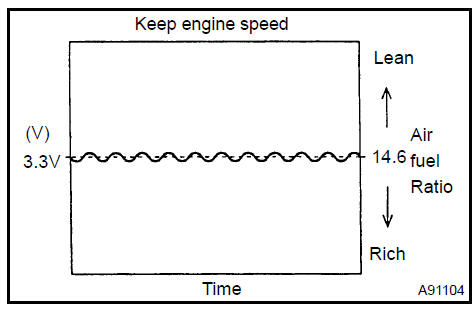
e. Keep the engine speed at 2,500 rpm and confirm that the displays of ”A/FS B1 S1” and ”A/FS B2 S1” are as shown in the illustration.
HINT:
-
The illustration may differ slightly from the display on the hand held tester.
-
Only the hand−held tester displays the waveform of A/F .
f. Confirm that the display of ”O2S B1 S2” changes between 0 V to 1 V with the engine speed at 2,500 rpm.
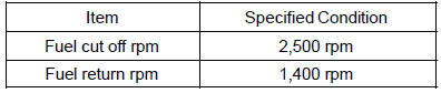
2. INSPECT FUEL CUT OFF RPM
-
Increase the engine speed to at least 3,500 rpm.
-
Use a sound scope to check for injector operating sounds.
-
Check that when the throttle lever is released, injector operation sounds stop momentarily (at 2,500 rpm) and then resume (at 1,400 rpm).
Standard
:
3. VISUALLY INSPECT HOSES, CONNECTIONS AND GASKETS
a. Check for cracks, leaks or damage.
HINT: Removal or problems with the engine oil dipstick, oil filler cap, PCV hose and other components may cause the engine to run improperly. Disconnection, looseness or cracks in the parts of the air induction system between the throttle body and cylinder head will allow air suction and cause the engine to run improperly.
If necessary, replace any damage parts.
Visually inspect hoses, connections and gaskets
4. Using Hand−Held Tester: INSPECT EVAP SYSTEM LINE
a. Warm up and stop the engine.
1. Warm up the engine to normal operating temperature.
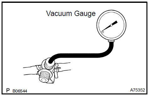
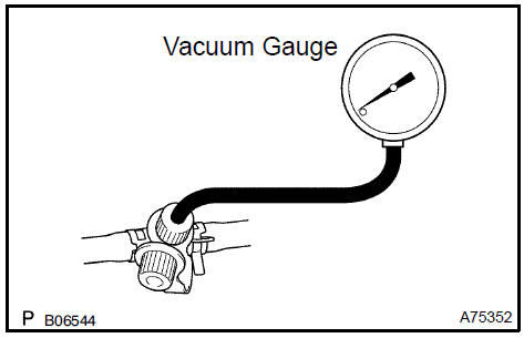
b. Install a vacuum gauge (EVAP control system test equipment vacuum gauge) to the EVAP service port on the purge line.
-
Connect the hand−held tester to the DLC3.
-
Start the engine.
-
Turn the hand−held tester main switch ON.
-
Use the ACTIVE TEST mode on the hand−held tester to operate the VSV for EVAP.
g. Check the vacuum while the engine is idling.
Standard:
Maintain at 0.368 to 19.713 in.Hg (5 to 268 in. Aq) for
over 5 seconds.
HINT: If the vacuum does not change, the hose connecting the VSV to the service port has come loose or is blocked, or the VSV is malfunctioning.
-
Stop the engine.
-
Disconnect the hand−held tester from the DLC3.
-
Disconnect the vacuum gauge from the EVAP service port on the purge line
k. Connect a pressure gauge to the EVAP service port on the purge line.
-
Connect the hand−held tester to the DLC3.
-
Turn the ignition switch ON.
-
Turn the hand−held tester main switch ON.
-
Use the ACTIVE TEST mode on the hand−held tester to operate the VSV for CCV.
NOTICE: In step m., the ignition switch should be ON, but the engine should not be running.
HINT: If the check is not completed within 10 minutes, the VSV for CCV will be reset and close automatically.
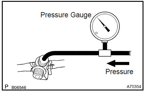
p. Check the pressure.
1. Add 13.5 to 15.5 in. Aq of pressure from the EVAP service port.
Standard:
2 minutes after the pressure is added, the gauge
should still read over 7.7 to 8.8 in. Aq.
HINT: If you cannot add pressure, the hose connecting the VSV for EVAP canister fuel tank has become disconnected or the VSV is open
2. Check if the pressure decreases when the fuel tank cap is removed while adding pressure.
HINT: If the pressure does not decrease when the fuel tank cap is removed, the hose connecting the service port to the fuel tank is blocked.
-
Turn the ignition switch OFF.
-
Disconnect the hand−held tester from the DLC3.
5. Not Using Hand−Held Tester: INSPECT EVAP SYSTEM LINE
a. Warm up and stop the engine.
1. Warm up the engine to normal operating temperature.
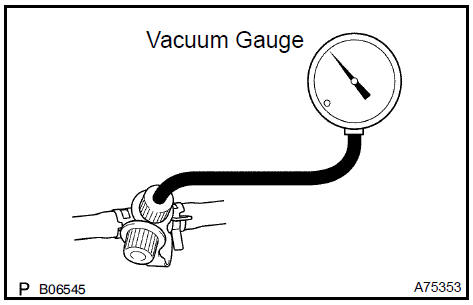
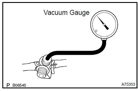
b. Install a vacuum gauge (EVAP control system test equipment vacuum gauge) to the EVAP service port on the purge line.
-
Disconnect the VSV for EVAP connector.
-
Connect the battery’s positive (+) and negative (−) leads to the VSV for EVAP terminals.
-
Start the engine.
f. Check the vacuum while the engine is idling.
Standard: Maintain at 0.368 to 19.713 in.Hg (5 to 268 in. Aq) for over 5 seconds.
HINT: If the vacuum does not change, the hose connecting the VSV to the service port has come loose or is blocked, or the VSV is malfunctioning.
-
Stop the engine.
-
Disconnect the battery’s positive (+) and negative (−) leads from the VSV for EVAP terminals.
-
Reconnect the VSV for EVAP connector.
-
Disconnect the vacuum gauge from the EVAP service port on the purge line.
k. Connect a pressure gauge to the EVAP service port on the purge line.
-
Disconnect the VSV for CCV.
-
Connect the battery’s positive (+) and negative (−) leads to the VSV for CCV terminals.
NOTICE: Incorrect electrode connection causes damage to the VSV.
Pay due attention when connecting the lead wire.
n. Check the pressure.
1. Add 13.5 to 15.5 in. Aq of pressure from the EVAP service port.
Standard:
2 minutes after the pressure is added, the gauge
should still read over 7.7 to 8.8 in. Aq.
HINT: If you cannot add pressure, the hose connecting the VSV for EVAP canister fuel tank has become disconnected or the VSV is open.
2 Check if the pressure decreases when the fuel tank cap is removed while adding pressure.
HINT: If the pressure does not decrease when the fuel tank cap is removed, the hose connecting the service port to the fuel tank is blocked.
-
Disconnect the battery’s positive (+) and negative (−) leads from the VSV for CCV terminals.
-
Reconnect the VSV for CCV connector.
-
Disconnect the pressure gauge from the EVAP service port on the purge line
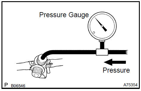
6. CHECK AIR TIGHTNESS IN FUEL TANK AND FILLER PIP
-
Disconnect the vent line hose from the fuel tank
-
Connect the pressure gauge to the fuel tank.
-
Apply pressure to the fuel tank to create an internal pressure of 4 kPa (41 gf/cm2, 0.58 psi).
-
Check that the internal pressure of the fuel tank is maintained for 1 minute.
-
Check the connected portions of each hose and pipe.
-
Check the installed parts on the fuel tank.
If malfunctions, damage or other problems are found, replace the fuel tank and filler pipe.
g. Reconnect the vent line hose to the fuel tank.
 Check air tightness in fuel tank and filler pip
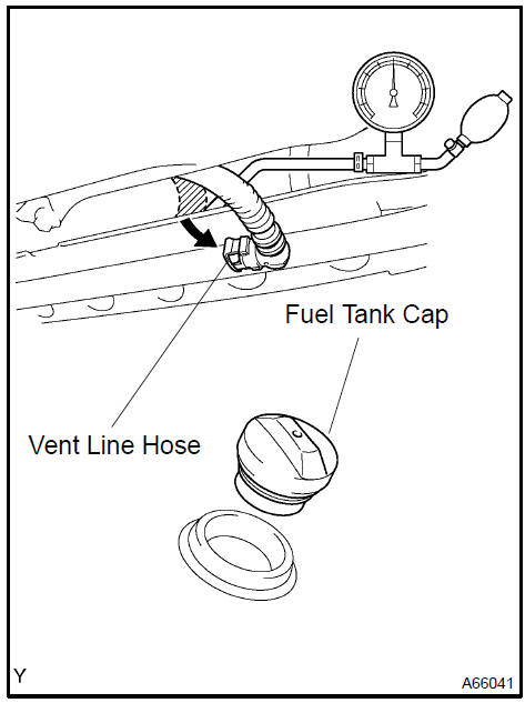
7. INSPECT FUEL CUTOFF VALVE AND FILL CHECK VALVE
-
Disconnect the vent line hose from the fuel tank
-
Connect the pressure gauge to the fuel tank.
-
Fill the fuel tank with fuel until full.
-
Apply pressure of 4 kPa (41 gf/cm2, 0.58 psi) to the vent port of the fuel tank.
HINT: It is necessary to check the amount of fuel in the fuel tank. When the fuel tank is full, the float valve of the fill check valve is closed and no air can pass through.
e. Remove the fuel tank cap, and check that pressure drops.
ressure does not drop, replace the fuel tank assembly.
f. Reconnect the vent line hose to the fuel tank.
 Inspect fuel cutoff valve and fill check valve
8. CHECK AIR INLET LINE
-
Disconnect the air inlet line hose from the charcoal canister.
-
Check that air can flow freely into the air inlet line.
If air cannot flow freely into the air inlet line, repair or replace it.
c. Reconnect the air inlet line hose to the charcoal canister.
Check air inlet line
9. INSPECT VAPOR PRESSURE
a. Check the power source voltage of the vapor pressure .
-
Turn the ignition switch ON.
-
Using a voltmeter, measure the voltage between connector terminals E8−18 (VC) and E8−28 (E2) of the ECM connectors.
Standard: 4.5 to 5.5 V
-
Turn the ignition switch OFF.
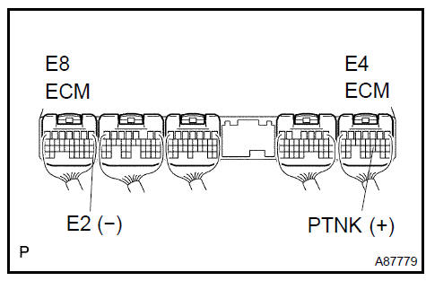
b. Check the power output of the vapor pressure .
-
Turn the ignition switch ON.
-
Remove the fuel tank cap.
-
Using a voltmeter, measure the voltage between terminals E4−21 (PTNK) and E8−28 (E2) of the ECM connectors.
Standard: 3.0 to 3.6 V
-
Reinstall the fuel tank cap.
INSPECTION
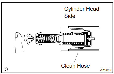
1. INSPECT VENTILATION VALVE SUB−ASSY
-
Install a clean hose to the ventilation valve.
-
Check ventilation valve operation.
1. Blow air into the cylinder head side, and check that air passes through easily.
CAUTION: Do not suck air through the valve. Petroleum substances inside the valve are harmful.
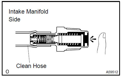
2. Blow air into the intake manifold side, and check that air passes through with difficulty.
If the result is not as specified, replace the ventilation valve.
c. Remove the clean hose from the ventilation valve.
2. INSPECT FUEL TANK CAP ASSY
a. Visually check if the cap and gasket are deformed or damaged.
Inspect fuel tank cap assy
3. INSPECT CHARCOAL CANISTER ASSY
a. Visually check the charcoal canister for cracks or damage.
If cracks or damage is found, replace the charcoal canister assy.
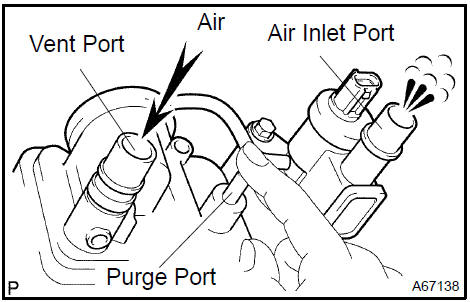
b. Check the charcoal canister operation.
1. While holding the purge port closed, blow air (0.39 kPa, 4.0 gf/cm2, 0.06 psi) into the vent port, and check that air flows from the air inlet port.
If the result is not as specified, replace the charcoal canister.
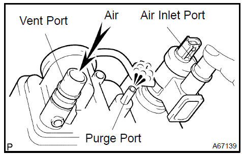
2. While holding the air inlet port closed, blow air (0.39 kPa, 4.0 gf/cm2, 0.06 psi) into the vent port, and check that air flows from the purge port.
If the result is not as specified, replace the charcoal canister.
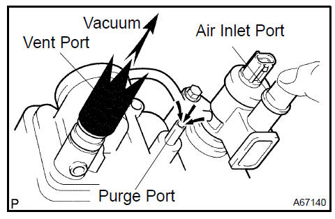
3. While holding the air inlet port closed, apply vacuum (3.43 kPa, 25.7 gf/cm2, 1.01 psi) to the vent port, and check that air is sucked in from the purge port.
If the result is not as specified, replace the charcoal canister.
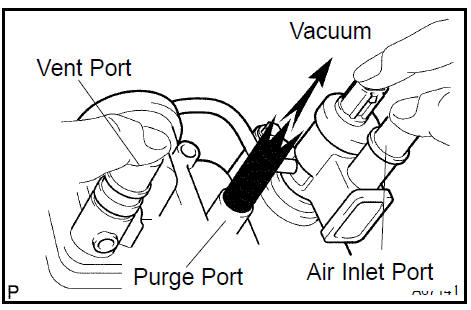
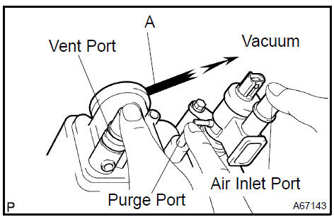
c. Check air tightness.
1. While holding the vent and air inlet ports closed, apply vacuum (3.43 kPa, 25.7 gf/cm2, 1.01 psi) to the purge port, and check that the vacuum is maintained for 1 minute.
HINT: In order to maintain air tightness, the check should be performed while holding the CCV terminal port closed.
If the result is not as specified, replace the charcoal canister.
d. Check the diaphragm.
-
Remove the air hose between ports A and B.
-
While holding the vent, purge and air inlet ports closed, apply vacuum (1.42 kPa, 11 mmHg, 0.42 in.Hg) into port A, and check that air is sucked in from port B.
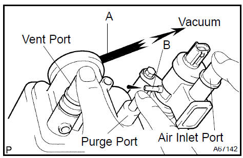
3. While holding the vent, purge and air inlet ports closed, apply vacuum (1.42 kPa, 11 mmHg, 0.42 in.Hg) into port A, and measure how long it takes for vacuum to drop.
Vacuum drop time: 10 seconds or more
If the result is not as specified, replace the charcoal canister.
4. Reinstall the air hose between ports A and B.
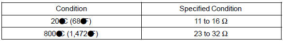
e. Check the VSV for open circuit.
1. Measure the resistance between the terminals.
Standard:
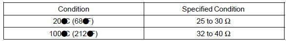
If the result is not as specified, replace the charcoal canister.
f. Check VSV operation.
1. Check that air flows from port A to ports B and C.
If the result is not as specified, replace the charcoal canister.
-
Apply battery positive voltage across the terminals.
-
Check that the valve is closed.
If the result is not as specified, replace the charcoal canister.
NOTICE: Incorrect electrode connection causes damage to the VSV.
Pay due attention when connecting the lead wire.
-
Check that air does not flow from port A to port B.
-
Check that air flows from port A to port C.
If the result is not as specified, replace the charcoal canister.
NOTICE: Incorrect electrode connection causes damage to the VSV.
Pay due attention when connecting the lead wire.
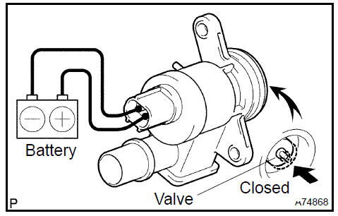
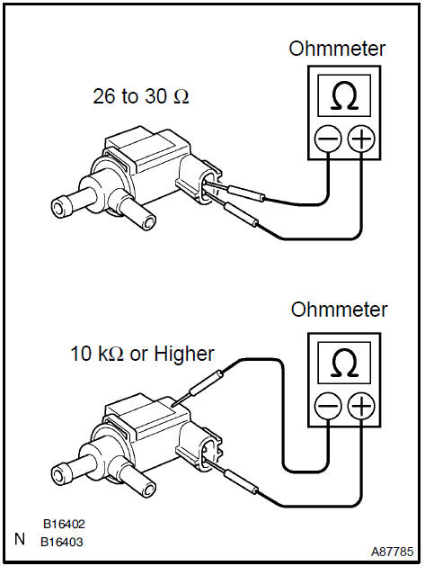
4. INSPECT VACUUM SWITCHING VALVE ASSY FOR EVAP
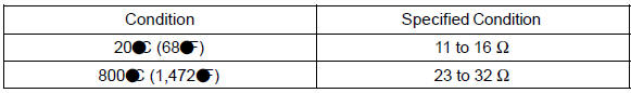
a. Check the VSV for open circuit.
1. Measure the resistance.
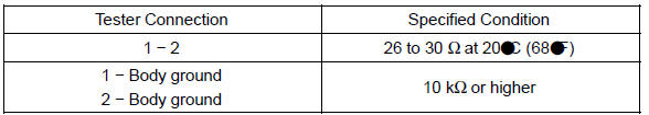
If the resistance is not as specified, replace the VSV assy.
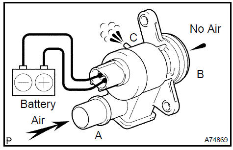
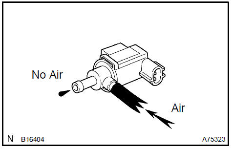
b. Check VSV operation.
1. Check that air does not flow from the port as shown in the illustration.
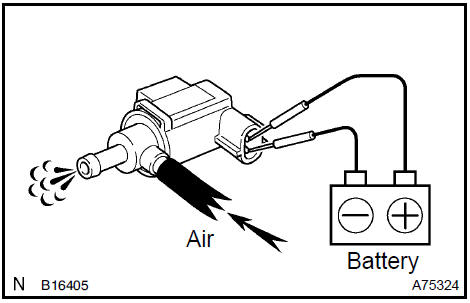
-
Apply battery positive voltage across the terminals.
-
Check that air flows from the port as shown in the illustration.
If the result is not as specified, replace the VSV assy.
5. INSPECT AIR FUEL RATIO
a. Measure the resistance between terminals 1 (HT) and 2 (+B).
Standard
:
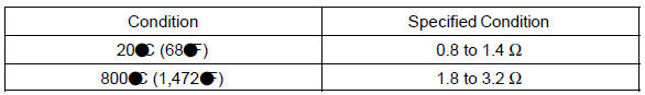
If the result is not as specified, replace the
6. INSPECT HEATED OXYGEN (BANK 1 2)
a. Measure the resistance between terminals 1 (HT) and 2 (+B).
Standard
:
If the result is not as specified, replace the .
7. INSPECT HEATED OXYGEN (BANK 2 2)
a. Measure the resistance between terminals 1 (HT) and 2 (+B).
Standard
:
If the result is not as specified, replace the .
Emission control system (2AZ−FE)(From July, 2003)
Charcoal canister assy (2AZ−FE)(From July, 2003)
Ventilation valve sub-assy (2AZ−FE)(From July, 2003)
Emission control system (1MZ−FE/3MZ−FE)
Charcoal canister assy (1MZ−FE/3MZ−FE)
Ventilation valve sub-assy (1MZ−FE/3MZ−FE)
Emission control system (2AZ−FE)(From July, 2003)
Toyota Camry XV30 (2002–2006) Service Manual
- Introduction
- Audio & visual system
- Automatic transmission / trans
- Brake
- Clutch
- Communication system
- Cooling
- Cruise control
- Drive shaft / propeller shaft
- Emission control
- Engine control system
- Engine hood/door
- Engine mechanical
- Exhaust
- Exterior/interior trim
- Front suspension
- Fuel
- Heater & air conditioner
- Ignition
- Instrument panel/meter
- Intake
- Lighting
- Lubrication
- Manual transmission/transaxle
- Parking brake
- Power steering
- Rear suspension
- Seat
- Service specifications
- Sliding roof/convertible
- Starting & charging
- Steering column
- Supplemental restraint system
- Theft deterrent & door lock
- Tire & wheel
- Windshield/windowglass/mirror
- Wiper & washer
- Wiring
Categories
