 Toyota Camry XV30 (2002–2006) Service ManualSupplemental restraint system
Horn button assy
Horn button assy
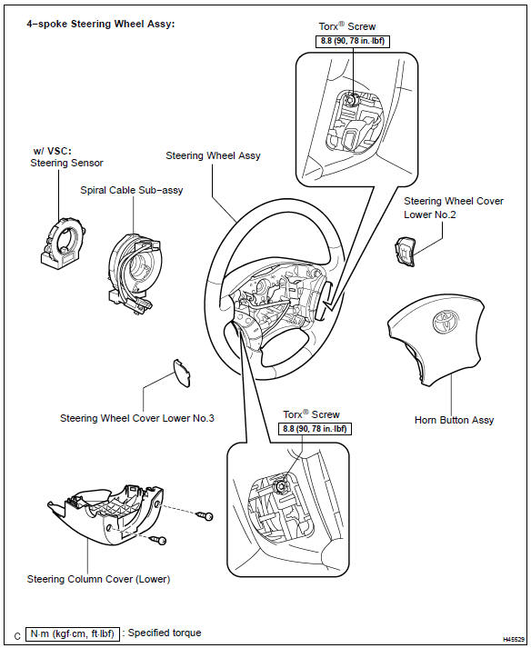
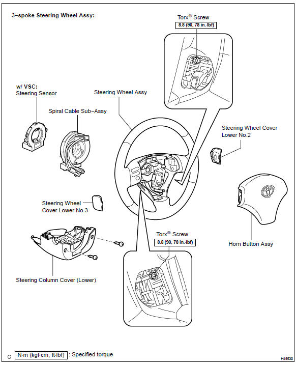
COMPONENTS
REPLACEMENT
HINT:
-
Installation is in the reverse order of removal.
-
There are two types of horn button assy: One is used with 3−spoke steering wheel assy and the other is used with 4−spoke steering wheel assy.
-
PRECAUTION
-
DISCONNECT BATTERY NEGATIVE TERMINAL
CAUTION: After removing the terminal, wait for at least 90 seconds before starting the operation.
3. REMOVE STEERING WHEEL COVER LOWER No.2
a. Using a screwdriver, remove the steering wheel cover lower No.2.
HINT: Tape up the screwdriver tip before use.
4. REMOVE STEERING WHEEL COVER LOWER No.3
a. Using a screwdriver, remove the steering wheel cover lower No.3.
HINT: Tape up the screwdriver tip before use.
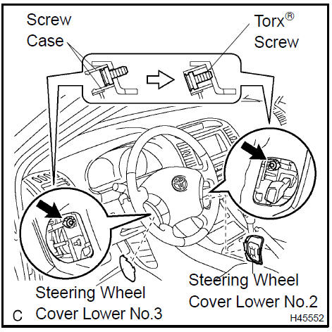
5. REMOVE HORN BUTTON ASSY
-
Place the front wheels facing straight ahead.
-
Using a torx) socket wrench (T30), loosen the 2 torx) screws until the groove along the screw circumference catches on the screw case.
-
Pull out the horn button assy from the steering wheel assy and support the horn button assy with one hand as shown in the illustration.
NOTICE: When removing the horn button assy, do not pull the airbag wire harness.
-
Disconnect the horn connector.
-
Disconnect the connector from the horn button assy.
NOTICE: When handling the airbag connector, take care not to damage the airbag wire harness.
f. Remove the horn button assy.
6. INSTALL HORN BUTTON ASSY
-
Support the horn button assy with one hand as shown in the illustration.
-
Connect the connector to the horn button assy.
NOTICE: When handling the airbag connector, take care not to damage the airbag wire harness.
c. Connect the horn connector.
-
Confirm that the circumference groove of the torx) screw fits in the screw case, and place the horn button assy onto the steering wheel assy.
-
Using a torx) socket wrench (T30), tighten the 2 torx) screws.
Torque: 8.8 N·m (90 kgf·cm, 78 in.Vlbf)
-
CONNECT BATTERY NEGATIVE TERMINAL
-
INSPECT HORN BUTTON ASSY
-
With the horn button assy installed on the vehicle, perform a visual check. If there are any defects as mentioned below, replace the horn button assy with a new one: Cuts, minute cracks or marked discoloration on the horn button assy top surface or in the grooved portion.
-
Make sure that the horn sounds.
HINT: If the horn does not sound, inspect the horn system
 Inspect horn button assy
9. INSPECT SRS WARNING LIGHT
DISPOSAL
HINT:
-
There are two types of horn button assy: One is used with 3−spoke steering wheel assy and the other is used with 4−spoke steering wheel assy.
-
The procedures listed below are for the 4−spoke steering wheel assy.
-
When scrapping a vehicle equipped with the SRS or disposing of the horn button assy, be sure to deploy the airbag first in accordance with the procedure described below. If any abnormality occurs with the airbag deployment, contact the SERVICE DEPT. of TOYOTA MOTOR SALES, U.S.A., INC.
CAUTION:
-
Never dispose of a horn button assy which has an undeployed airbag.
-
The airbag produces an exploding sound when it is deployed, so perform the operation outdoors and where it will not create a nuisance to nearby residents.
-
When deploying the airbag, always use the specified SST (SRS Airbag Deployment Tool). Perform the operation in a place away from electrical noise.
-
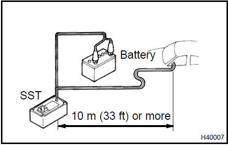
When deploying an airbag, perform the operation at least 10 m (33 ft) away from the horn button assy.
The horn button assy becomes extremely hot when the airbag is deployed, so do not touch it for at least 30 minutes after deployment.
-
Use gloves and safety glasses when handling a horn button assy with a deployed airbag.
-
Do not apply water, etc. to a horn button assy with the deployed airbag.
-
Always wash your hands with water after completing the operation.
1. DISPOSE OF HORN BUTTON ASSY (WHEN INSTALLED IN VEHICLE)
HINT: Prepare a battery as the power source to deploy the airbag.
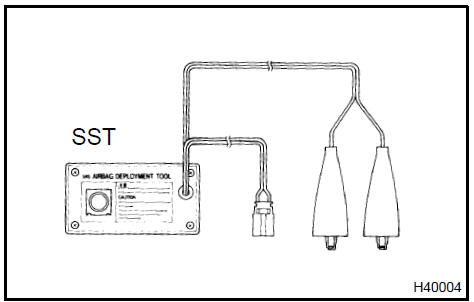
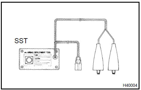
a. Check function of the SST.
SST 09082−00700
CAUTION: When deploying the airbag, always use the specified SST: SRS Airbag Deployment Tool.
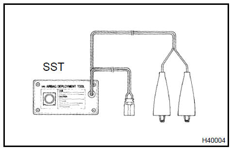
1. Connect the SST to the battery.
Connect the red clip of the SST to the battery positive (+) terminal and the black clip of the SST to the battery negative (−) terminal.
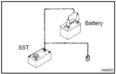
2. Check function of the SST.
Press the SST activation switch, and check that the LED of the SST activation switch comes on.
CAUTION:
-
Do not connect the SST connector (yellow colored one) to the airbag.
-
If the LED comes on when the activation switch is not being pressed, SST malfunction is possible, so replace the SST with a new one.
3. Disconnect the SST from the battery.
-
Precaution.
-
Disconnect the battery negative terminal.
CAUTION: After removing the terminal, wait for at least 90 seconds before starting the operation.
d. Remove the steering column cover (lower).
1. While turning the steering wheel assy to the right and left, remove the 2 screws and steering column cover (lower).
e. Install the SST.
CAUTION: Check that there is no looseness in the steering wheel assy and horn button assy.
1. Disconnect the airbag connector (yellow colored one) from the spiral cable sub−assy.
NOTICE: When handling the airbag connector, take care not to damage the airbag wire harness.
2. Connect the SST connector to the airbag connector of the spiral cable sub−assy.
SST 09082−00700, 09082−00780
NOTICE: To avoid damaging the SST connector and wire harness, do not lock the secondary lock of the twin lock.
-
Move the SST at least 10 m (33 ft) away from the vehicle front side window.
-
Maintaining enough clearance for the SST wire harness in the front side window, close all doors and windows of the vehicle.
NOTICE: Take care not to damage the SST wire harness.
5. Connect the red clip of the SST to the battery positive (+) terminal and the black clip of the SST to the negative (−) terminal.
f. Deploy the airbag.
-
Check that no one is inside the vehicle or within a 10 m (33 ft) radius of the vehicle.
-
Press the SST activation switch and deploy the airbag.
CAUTION:
-
When deploying the airbag, make sure that no one is near the vehicle.
-
The horn button assy becomes extremely hot when the airbag is deployed, so do not touch it for at least 30 minutes after deployment.
-
Use gloves and safety glasses when handling a horn button assy with a deployed airbag.
-
Do not apply water, etc. to a horn button assy with a deployed airbag.
-
Always wash your hands with water after completing the operation.
HINT: The airbag is deployed as the LED of the SST activation switch comes on.
2. DISPOSE OF HORN BUTTON ASSY (WHEN NOT INSTALLED IN VEHICLE)
NOTICE:
-
When disposing of the horn button assy, never use the customer’s vehicle to deploy the airbag.
-
Be sure to follow the procedure detailed below when deploying the airbag.
HINT: Prepare a battery as the power source to deploy the airbag.
-
Check the function of the SST .
-
Remove the horn button assy.
CAUTION:
-
When removing the horn button assy, work must be started 90 seconds after the ignition switch is turned to the ”LOCK” position and the negative (−) terminal cable is disconnected from the battery.
-
When storing the horn button assy, keep the airbag deployment side facing upward.
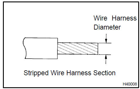
c. Using a service−purpose wire harness for the vehicle, tie down the horn button assy to the disc wheel.
Wire harness: Stripped wire harness section 1.25 mm2 or more (0.0019 in.2 or more
)
CAUTION: If the wire harness is too thin or an alternative object is used to tie down the horn button assy, it may be snapped by the shock when the airbag is deployed. Always use a wire harness for vehicle use with an area of at least 1.25 mm2 (0.0019 in.2).
HINT: To calculate the area of the stripped wire harness section: Area = 3.14 x (Diameter)2 divided by 4
1. Install the 2 bolts with washers into the 2 bolt holes on the horn button assy.
Bolt:
L: 35.0 mm (1.387 in.)
M: 6.0 mm (0.236 in.)
Pitch: 1.0 mm (0.039 in.)
NOTICE:
-
Tighten the bolts by hand until they become difficult to turn.
-
Do not tighten the bolts excessively.
2. After connecting the SST below to each other, connect them to the horn button assy.
SST 09082−00802 (09082−10801, 09082−30801)
3. Using 3 wire harnesses, wind wire harness at least 2 times each around the bolts installed on the left and right sides of the horn button assy.
CAUTION:
-
Tightly wind the wire harness around the bolts so that there is no slack.
-
Make sure that the wire harness is tight. If there is slack in wire harness, the horn button assy may become loose due to the shock when the airbag is deployed.
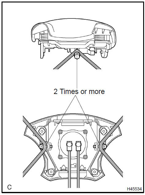
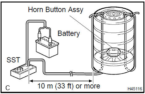
4. Face the airbag deployment side of the horn button assy upward. Separately tie the left and right sides of the horn button assy to the disc wheel through the hub nut holes. Position the SST connector so that it hangs downward through the hub hole in the disc wheel.
CAUTION:
-
Make sure that the wire harness is tight. If there is slack in wire harness, the horn button assy may become loose due to the shock when the airbag is deployed.
-
Always tie down the horn button assy with the airbag deployment side facing upward.
NOTICE: The disc wheel will be marked by the airbag deployment, so use an extra disc wheel.
d. Install the SST.
SST 09082−00700
CAUTION: Place the disc wheel on level ground.
1. Connect the connector of the SST.
NOTICE: To avoid damaging the SST connector and wire harness, do not lock the secondary lock of the twin lock. Also, secure some slack for the SST wire harness inside the disc wheel.
2. Move the SST to at least 10 m (33 ft) away from the horn button assy tied down to the disc wheel.
e. Cover the horn button assy with a cardboard box or tires.
1. Covering method using a cardboard box: Cover the horn button assy with the cardboard box and place weights on the cardboard box in 4 places totalling at least 190 N (20 kg, 44 lb).
Size of cardboard box:
Must exceed the following dimensions:
X = 460 mm (18.11 in.)
Y = 650 mm (25.59 in.)
NOTICE:
-
When the dimension Y of the cardboard box exceeds the diameter of the disc wheel with tire which the horn button assy is tied to, X should be the following size.
X = 460 mm (18.11 in.) + width of tire
-
If a cardboard box which is smaller than the specified size is used, the cardboard box will be broken by the shock from the airbag deployment.
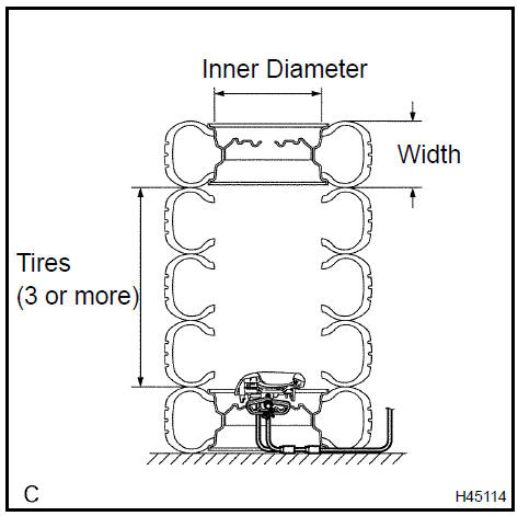
2. Covering method using tires: Place at least 3 tires without disc wheels on the tire with disc wheel which the horn button assy is tied to.
Place the tire with disc wheel on them.
Tire size: Must exceed the following dimensions Width: 185 mm (7.28 in.) Inner diameter: 360 mm (14.17 in.)
CAUTION: Do not use tires with disc wheels except on the top and bottom.
NOTICE:
-
The tires may be marked by the airbag deployment, so use an extra tire.
-
Do not place the SST connector under the tire because it could be damaged.
3. Tie the tires together with 2 wire harnesses.
CAUTION: Make sure that the wire harness is tight. Looseness in the wire harness results in the tires coming free due to the shock when the airbag is deployed.
f. Deploy the airbag.
-
Connect the red clip of the SST to the battery positive (+) terminal and the black clip of the SST to the battery negative (−) terminal.
-
Check that no one is within a 10 m (33 ft) radius of the disc wheel which the horn button assy is tied to.
-
Press the SST activation switch and deploy the airbag.
CAUTION: When deploying the airbag, make sure that no one is near the tire.
HINT: The airbag is deployed as the LED of the SST activation switch comes on.
g. Dispose of the horn button assy.
CAUTION:
-
The horn button assy becomes extremely hot when the airbag is deployed, so do not touch it for at least 30 minutes after deployment.
-
Use gloves and safety glasses when handling a horn button assy with a deployed airbag.
-
Do not apply water, etc. to a horn button assy with a deployed airbag.
-
Always wash your hands with water after completing the operation.
-
Remove the horn button assy from the disc wheel.
-
Place the horn button assy in a plastic bag, tie it tightly and dispose of it as other general part disposal.
Horn button assy
Spiral cable sub-assy
Front passenger airbag assy (From July, 2003)
Curtain shield air bag assy LH
Front seat airbag assy RH
Air bag sensor assy center
Air bag front RH sensor
Air bag sensor front LH
Air bag sensor front LH
Air bag sensor front LH
Side air bag sensor assy RH
Air bag sensor rear LH
Seat position air bag sensor (From July, 2003)
Occupant classification ecu (From July, 2003)
Toyota Camry XV30 (2002–2006) Service Manual
- Introduction
- Audio & visual system
- Automatic transmission / trans
- Brake
- Clutch
- Communication system
- Cooling
- Cruise control
- Drive shaft / propeller shaft
- Emission control
- Engine control system
- Engine hood/door
- Engine mechanical
- Exhaust
- Exterior/interior trim
- Front suspension
- Fuel
- Heater & air conditioner
- Ignition
- Instrument panel/meter
- Intake
- Lighting
- Lubrication
- Manual transmission/transaxle
- Parking brake
- Power steering
- Rear suspension
- Seat
- Service specifications
- Sliding roof/convertible
- Starting & charging
- Steering column
- Supplemental restraint system
- Theft deterrent & door lock
- Tire & wheel
- Windshield/windowglass/mirror
- Wiper & washer
- Wiring
Categories
