 Toyota Camry XV30 (2002–2006) Service ManualEngine mechanical
Camshaft (RH BANK) (1MZ−FE/3MZ−FE)
Camshaft (RH BANK) (1MZ−FE/3MZ−FE)
REPLACEMENT
-
DRAIN ENGINE COOLANT
-
REMOVE V−BANK COVER SUB−ASSY
-
REMOVE FRONT SUSPENSION UPPER BRACE CENTER (W/ FRONT SUSPENSION BRACE UPPER CENTER)
-
REMOVE AIR CLEANER ASSEMBLY WITH HOSE
-
REMOVE INTAKE AIR SURGE TANK
-
REMOVE SPARK PLUG
-
REMOVE CYLINDER HEAD COVER SUB−ASSY
-
REMOVE FRONT WHEEL RH
-
REMOVE FRONT FENDER APRON SEAL RH
-
REMOVE V (COOLER COMPRESSOR TO CRANKSHAFT PULLEY) BELT No.1
-
REMOVE VANE PUMP V BELT
-
REMOVE ENGINE MOVING CONTROL ROD
-
REMOVE ENGINE MOUNTING STAY No.2 RH
-
REMOVE GENERATOR BRACKET No.2
-
REMOVE CRANKSHAFT PULLEY
-
REMOVE TIMING BELT No.1 COVER
-
REMOVE TIMING BELT No.2 COVER
-
REMOVE ENGINE MOUNTING BRACKET RH
-
REMOVE TIMING BELT GUIDE No.2
-
REMOVE TIMING BELT
-
REMOVE TIMING BELT IDLER SUB−ASSY No.2
-
REMOVE CAMSHAFT TIMING PULLEY
a Using SST, remove the bolt and RH timing pulley.
SST 09960−10010 (09962−01000, 09963−01000), 09249−63010
b. Using SST, remove the LH timing pulley.
SST 09960−10010 (09962−01000, 09963−01000)
HINT: Arrange the camshaft timing pulleys (RH and LH sides) so that they can be returned to the original locations when reassembling.
23. REMOVE TIMING BELT No.3 COVER
-
Disconnect the 3 engine wire harness clamps from the timing belt No. 3 cover.
-
Remove the 6 bolts and the timing belt cover.
Remove timing belt No.3 Cover
24. REMOVE CAMSHAFT
NOTICE: Since the thrust clearance of the camshaft is small, the camshaft must be kept level while it is being removed. If the camshaft is not kept level, damage to the cylinder head or to the camshaft may result. To avoid this, the following steps must be carried out.
a. Align the camshaft drive and driven gear’s timing marks (2 dot marks each) by turning the camshaft with a wrench.
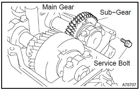
b) Secure the exhaust camshaft sub−gear to the main gear with a service bolt.
Recommended service bolt:
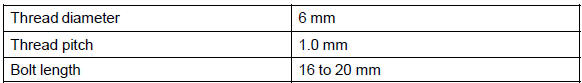
Torque: 5.4 N·m (55 kgf·cm, 48 in.·lbf)
HINT: When removing the camshaft, make certain that the torsional spring force of the sub−gear has been eliminated by installation of the service bolt.
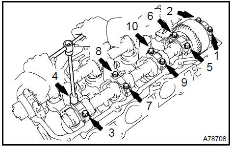
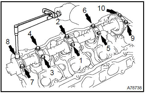
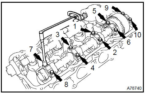
c. Uniformly loosen and remove the 10 bearing cap bolts in the sequence shown in the illustration. Remove the 5 bearing caps and the camshaft.
NOTICE:
-
Do not pry out the camshaft.
-
Be careful not to damage the portion of the cylinder head receiving the shaft thrust.
25. REMOVE No.2 CAMSHAFT
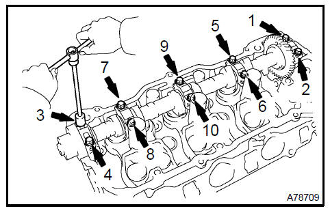
a. Uniformly loosen and remove the 10 bearing cap bolts in the sequence shown in the illustration. Remove the 5 bearing caps and the No. 2 camshaft.
NOTICE:
-
Do not pry out the camshaft.
-
Be careful not to damage the portion of the cylinder head receiving the shaft thrust.
b. Remove the oil seal from the No. 2 camshaft.
Remove No.2 Camshaft
26. REMOVE CAMSHAFT TIMING GEAR ASSY
NOTICE: Do not remove or install the camshaft timing gear (VVT−i) unless you are replacing the VVT−i or the camshaft.
a. Clamp the camshaft in a vise on the hexagonal lobe.
NOTICE: Do not damage the camshaft.
b. Using a 46 mm socket wrench, remove the lock nut by turning it clockwise.
NOTICE:
-
Remove the locknut with the lock−pin engaged and locked at the extreme retarded angle position.
-
The lock nut has LH threads.
-
Only use the socket wrench. Other tools will deform the cam angle rotor.
c. Remove the timing gear (VVT−i).
NOTICE: Never remove the 3 bolts on the gear.
If it is difficult to remove the VVT−i, tap it lightly using a plastic− faced hammer and then remove it.
27. REMOVE CAMSHAFT SUB GEAR
a. Clamp the camshaft in a vise on the hexagonal lobe.
NOTICE: Do not damage the camshaft.
b. Using SST, turn the sub gear counterclockwise, and remove the service bolt.
SST 09960−10010 (09962−01000, 09963−00500)
-
Using snap ring pliers, remove the snap ring.
-
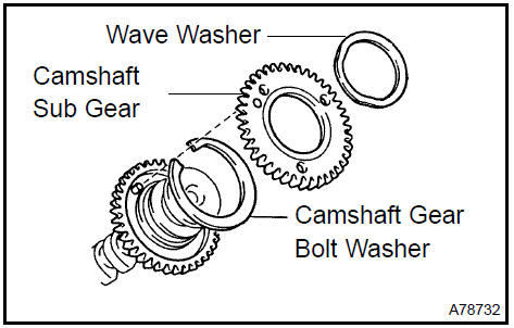
Remove the wave washer, camshaft sub gear and camshaft gear spring.
28. INSTALL CAMSHAFT SUB GEAR
a. Clamp the camshaft in a vise on the hexagonal lobe.
NOTICE: Do not damage the camshaft.
b. Install the camshaft gear bolt washer and the camshaft sub gear.
HINT: Attach the pins on the gears to the gear spring ends.
c. Install the wave washer.
d. Using snap ring pliers, install the snap ring.
-
Using SST, align the holes of the camshaft main gear and sub gear by turning the camshaft sub gear counterclockwise, and temporarily install a service bolt.
SST 09960−10010 (09962−01000, 09963−00500)
-
Align the gear teeth of the main gear and sub gear, and tighten the service bolt.
Torque: 5.4 N·m (55 kgf·cm, 48 in.·lbf)
NOTICE: Do not damage the camshaft journals.
HINT: When installing the camshaft, make certain that the torsional spring force of the sub gear has been eliminated by installation of the service bolt.
29. INSTALL CAMSHAFT TIMING GEAR ASSY
a. Align the alignment pin with the alignment pin groove and install the VVT−i on the camshaft.
NOTICE: Install the VVT−i with the lock−pin engaged and locked at the most retarded angle position.
b. Apply engine oil on the nut, the mounting surface of the VVT−i and the screw threads.
NOTICE:
-
Be sure to apply the oil, otherwise the specified torque cannot be obtained.
-
A new nut must be used when replacing the the VVT−i unit.
c. Using a 46 mm socket wrench, install and tighten the lock nut by turning it counterclockwise.
Torque: 150 N·m (1,530 kgf·cm, 111 ft·lbf)
NOTICE:
-
The lock nut has LH threads.
-
Only use the socket wrench. Other tools will deform the cam angle rotor.
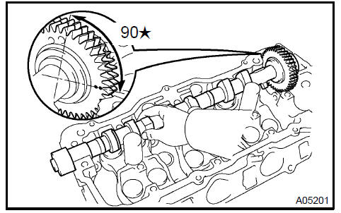
30. INSTALL No.2 CAMSHAFT
NOTICE: Since the thrust clearance of the camshaft is small, the camshaft must be held level while it is being installed. If the camshaft is not level, the portion of the cylinder head receiving the shaft thrust may crack or be damaged, causing the camshaft to seize or break. To avoid this, the following steps must be carried out.
-
Apply new engine oil to the thrust portion and journal of the camshaft.
-
Place the No. 2 camshaft at a 90 angle of the timing mark (2 dot marks) on the cylinder head.
-
Apply MP grease to a new oil seal lip.
d. Install the oil seal to the camshaft.
NOTICE:
-
Do not turn over the oil seal lip.
-
Insert the oil seal until it stops.
-
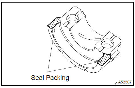
Remove any old packing material from the contact surface.
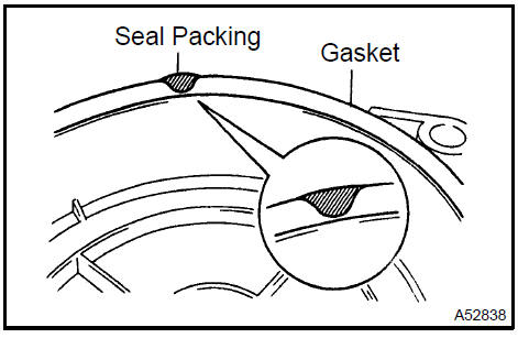
-
Apply seal packing to the No. 1 bearing cap as shown in the illustration.
Seal packing: Part No. 08826−00080 or equivalent
NOTICE:
-
Install the No. 1 bearing cap within 5 minutes after applying seal packing.
-
Do not expose the seal to engine oil for at least 2 hours after installing.
-
Install the 5 bearing caps in their proper locations.
-
Apply a light coat of engine oil on the threads of the bearing cap bolts.
i. Uniformly tighten the 10 bearing cap bolts in the sequence shown in the illustration.
Torque: 16 N·m (163 kgf·cm, 12 ft·lbf)
31. INSTALL CAMSHAFT
NOTICE: Since the thrust clearance of the camshaft is small, the camshaft must be held level while it is being installed. If the camshaft is not level, the portion of the cylinder head receiving the shaft thrust may crack or be damaged, causing the camshaft to seize or break. To avoid this, the following steps must be carried out.
-
Apply new engine oil to the thrust portion and journal of the camshaft.
-
Align the camshaft drive and driven gear’s timing marks (2 dot marks each).
-
Place the camshaft on the cylinder head.
-
Install the 5 bearing caps in their proper locations.
-
Apply a light coat of engine oil on the threads of the bearing cap bolts.
-
Uniformly tighten the 10 bearing cap bolts in the sequence shown in the illustration.
Torque: 16 N·m (163 kgf·cm, 12 ft·lbf)
-
Remove the service bolt.
32. INSTALL TIMING BELT No.3 COVER
a. Visually check for cracks and breaks in the gasket of the timing belt cover.
HINT: If water is entering through cracks or breaks in the gasket, repair according to these guidelines: 1) if the crack length is within 2 to 3 cm (0.79 to 1.18 in.), repair with seal packing; or 2) if the crack length is over 3 cm (1.18 in.), replace the gasket.
b. When repairing the timing belt cover gasket, follow the procedure below.
1. Repair the cracks and breaks by applying the seal packing to the damaged area.
Seal packing: Part No. 08826−00080 or equivalent
NOTICE: When applying the seal packing, apply it as wide and high as the gasket.
c. If the timing belt cover gasket needs to be replaced, follow the procedure below.
1. Using a screwdriver and gasket scraper, remove the remaining gasket.
NOTICE: Be careful not to damage the timing belt cover.
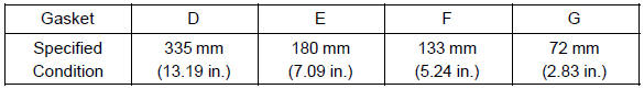
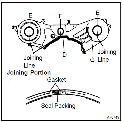
2. Remove the backing paper from a new gasket, and affix the gasket along the groove of the timing belt cover as shown in the illustration.
NOTICE:
-
Affix the gasket in the center of the groove.
-
At the corners, try to keep the gasket thickness uniform.
Length:
3. If there is a gap on the joint of the gasket, apply seal packing to close the gap.
Seal packing: Part No. 08826−00080 or equivalent
NOTICE: When applying the seal packing, apply it as wide and high as the gasket.
d. Install the timing belt cover with the 6 bolts.
Torque: 8.5 N·m (87 kgf·cm, 76 in.·lbf)
33. INSTALL CAMSHAFT TIMING PULLEY
a. Install the camshaft timing pulley with the belt guide properly oriented and tighten the bolt temporarily.
HINT:
-
Face the belt guide of the RH timing pulley towards the front of the engine.
-
Face the belt guide of the LH timing pulley towards the rear of the engine.
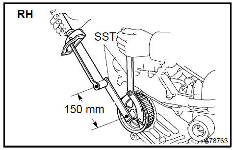
b. Using SST, tighten the RH pulley bolt.
SST 09960−10010 (09962−01000, 09963−01000),
09249−63010
Torque: 125 N·m (1,275 kgf·cm, 92 ft·lbf)
NOTICE: The torque specification above is the SST without extension tool specification. Use the special formula to calculate the SST with extension tool torque specification.
Extended length of SST (09249−63010): 150 mm (5.91 in.)
c. Using SST, tighten the LH pulley bolt.
SST 09960−10010 (09962−01000, 09963−01000) Torque: 125 N·m (1275 kgf·cm, 92 ft·lbf)
-
INSTALL TIMING BELT IDLER SUB−ASSY No.2 Torque: 43 N·m (438 kgf·cm, 32 ft·lbf)
-
INSPECT TIMING BELT
-
INSTALL TIMING BELT
-
INSTALL TIMING BELT TENSIONER ASSY
-
INSTALL TIMING BELT GUIDE No.2
-
INSTALL ENGINE MOUNTING BRACKET RH Torque: 28 N·m (286 kgf·cm, 21 ft·lbf)
-
INSTALL TIMING BELT No.2 COVER
-
INSTALL TIMING BELT No.1 COVER
-
INSTALL CRANKSHAFT PULLEY
-
INSTALL GENERATOR BRACKET No.2 Torque: 28 N·m (286 kgf·cm, 21 ft·lbf)
-
INSTALL ENGINE MOUNTING STAY No.2 RH
-
INSTALL ENGINE MOVING CONTROL ROD
-
INSPECT VALVE CLEARANCE
-
ADJUST VALVE CLEARANCE
-
INSTALL VANE PUMP V BELT
-
INSTALL V (COOLER COMPRESSOR TO CRANKSHAFT PULLEY) BELT No.1
-
INSPECT DRIVE BELT TENSION
-
INSTALL CYLINDER HEAD COVER SUB−ASSY
-
INSTALL SPARK PLUG Torque: 8.0 N·m (82 kgf·cm, 71 in.·lbf)
-
INSTALL INTAKE AIR SURGE TANK
-
INSTALL AIR CLEANER ASSEMBLY WITH HOSE
-
CONNECT VACUUM HOSES
-
INSTALL FRONT SUSPENSION UPPER BRACE CENTER (W/ FRONT SUSPENSION BRACE UPPER CENTER) Torque: 80 N·m (816 kgf·cm, 59 ft·lbf)
-
INSTALL V−BANK COVER SUB−ASSY
-
INSTALL FRONT WHEEL RH
-
ADD ENGINE COOLANT
-
CHECK FOR ENGINE COOLANT LEAKS
Engine (2AZ−FE) (From July, 2003)
Timing gear case or timing chain case oil seal (2AZ−FE)(From July, 2003)
Engine rear oil seal (2AZ−FE)(From July, 2003)
Cylinder head assy (2AZ−FE) (From July, 2003)
Cylinder block assy (2AZ−FE)(From July, 2003)
Engine (1MZ−FE/3MZ−FE)
Drive belt (1MZ−FE/3MZ−FE)
Valve clearance (1MZ−FE/3MZ−FE)
Partial engine assy (1MZ−FE/3MZ−FE)
Partial engine assy (2AZ−FE)(From July, 2003)
Partial engine assy (1MZ−FE/3MZ−FE)
Timing belt (1MZ−FE/3MZ−FE)
Camshaft (RH BANK) (1MZ−FE/3MZ−FE)
Camshaft (LH BANK) (1MZ−FE/3MZ−FE)
Cylinder head gasket (1MZ−FE/3MZ−FE)
Cylinder head gasket No.2 (1MZ−FE/3MZ−FE)
Oil pump seal (1MZ−FE/3MZ−FE)
Engine rear oil seal (1MZ−FE/3MZ−FE)
Cylinder head assy (1MZ−FE/3MZ−FE)
Cylinder block assy (1MZ−FE/3MZ−FE)
Partial engine assy (2AZ−FE)(From July, 2003)
Drive belt (2AZ−FE)(From July, 2003)
Valve clearance (2AZ−FE)
Chain (2AZ−FE)(From July, 2003)
Camshaft (2AZ−FE)(From July, 2003)
Cylinder head gasket (2AZ−FE)(From July, 2003)
Toyota Camry XV30 (2002–2006) Service Manual
- Introduction
- Audio & visual system
- Automatic transmission / trans
- Brake
- Clutch
- Communication system
- Cooling
- Cruise control
- Drive shaft / propeller shaft
- Emission control
- Engine control system
- Engine hood/door
- Engine mechanical
- Exhaust
- Exterior/interior trim
- Front suspension
- Fuel
- Heater & air conditioner
- Ignition
- Instrument panel/meter
- Intake
- Lighting
- Lubrication
- Manual transmission/transaxle
- Parking brake
- Power steering
- Rear suspension
- Seat
- Service specifications
- Sliding roof/convertible
- Starting & charging
- Steering column
- Supplemental restraint system
- Theft deterrent & door lock
- Tire & wheel
- Windshield/windowglass/mirror
- Wiper & washer
- Wiring
Categories
