 Toyota Camry XV30 (2002–2006) Service ManualEngine mechanical
Cylinder block assy (1MZ−FE/3MZ−FE)
Cylinder block assy (1MZ−FE/3MZ−FE)
COMPONENTS
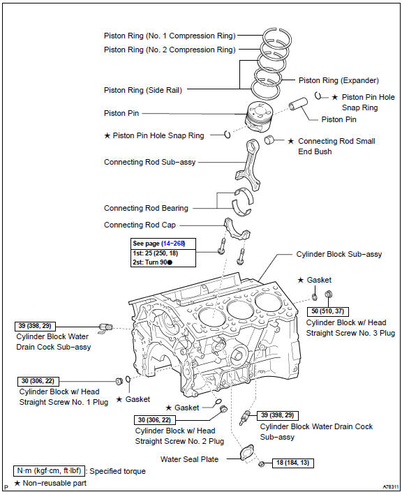
OVERHAUL
-
REMOVE CYLINDER BLOCK WATER DRAIN COCK SUB−ASSY
-
REMOVE WATER SEAL PLATE
-
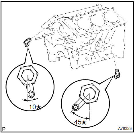
REMOVE CYLINDER BLOCK W/HEAD STRAIGHT SCREW No.1 PLUG
a. Using a socket hexagon wrench 10, remove the screw plug.
4. REMOVE CYLINDER BLOCK W/HEAD STRAIGHT SCREW No.2 PLUG
a. Using a socket hexagon wrench 10, remove the screw plug.
5. REMOVE CYLINDER BLOCK W/HEAD STRAIGHT SCREW No.3 PLUG
a. Using a socket hexagon wrench 10, remove the screw plug.
6. INSPECT CONNECTING ROD THRUST CLEARANCE
a. Using a dial indicator, measure the thrust clearance while moving the connecting rod back and forth.
Specified thrust clearance: 0.15 to 0.35 mm (0.0059 to 0.0138 in.)
If the thrust clearance is greater than the maximum, replace the connecting rod assemblys.. If necessary, replace the crankshaft.
Connecting rod thickness: 20.80 to 20.85 mm (0.8189 to 0.8209 in.)
7. INSPECT CONNECTING ROD OIL CLEARANCE
-
Check that the matchmarks on the connecting rod and cap are aligned to ensure correct reassembly.
-
Remove the 2 connecting rod cap bolts.
-
Clean the crank pin, the bearing and the connecting rod.
-
Check the crank pin and bearing for pitting and scratches.
e. Lay a strip of plastigage across the crank pin.
-
Check that the protrusion of the connecting rod cap is facing the correct direction.
-
Apply a light coat of engine oil on the threads of the connecting rod cap bolts.
h. Tighten the bolts in several steps by the specified torque.
Torque: 25 N·m (250 kgf·cm, 18 ft·lbf)
-
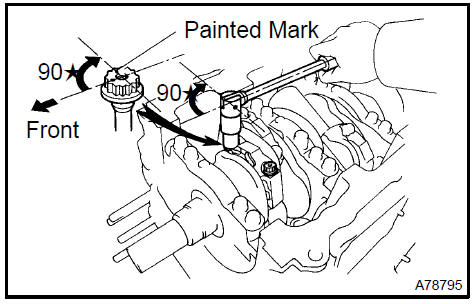
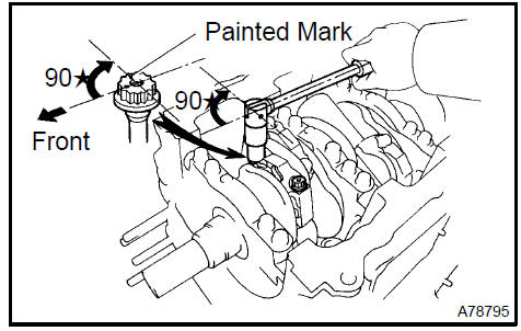
Mark the front side of each connecting cap bolt with paint.
-
Retighten the cap bolts by 90 as shown in the illustration.
NOTICE: Do not turn the crankshaft.
k. Remove the 2 bolts, the connecting rod cap and the lower bearing.
l. Measure the plastigage at its widest point.
Specified oil clearance: 0.038 to 0.080 mm (0.0015 to 0.0031 in.)
If the oil clearance is greater than the maximum, replace the bearings. If necessary, grind or replace the crankshaft.
m. Completely remove the plastigage.
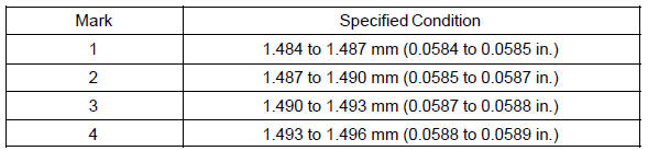
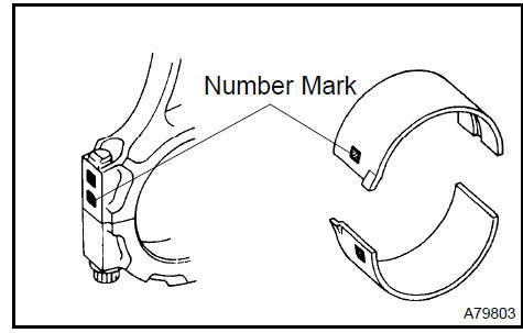
HINT: If replacing the bearing, replace it with one that has the same number as the connecting rod. There are 4 sizes of standard bearings: 1, 2, 3 and 4.
Standard bearing center wall thickness:
8. REMOVE PISTON SUB−ASSY W/CONNECTING ROD
-
Using a ridge reamer, remove all the carbon from the top of the cylinder.
-
Push out the piston and the connecting rod assembly from the top of the cylinder block.
HINT:
-
Keep the bearings, the connecting rod and the cap together.
-
Arrange the piston and the connecting rod assemblies in correct order so they can be returned to the original locations when reassembling.
Remove piston sub-assy W/connecting rod
-
REMOVE CONNECTING ROD BEARING
-
REMOVE PISTON RING SET
-
Using a piston ring expander, remove the 2 compression rings.
-
Remove the 2 side rails and oil ring by hand.
 Remove piston ring set
11. REMOVE PISTON PIN HOLE SNAP RING
a. Using a small screwdriver, pry out the 2 snap rings.
Remove piston pin hole snap ring
12. REMOVE W/PIN PISTON SUB−ASSY
a. Gradually heat the piston to approximately 80 C(176 F).
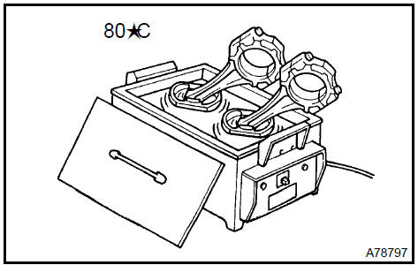
b. Using a plastic−faced hammer and a brass bar, lightly tap out the piston pin and remove the connecting rod.
HINT:
-
The piston and pin are a matched set.
-
Store the pistons, the pins, the rings, the connecting rods and the bearings in correct order so that they can be returned to the original locations when re assembling.
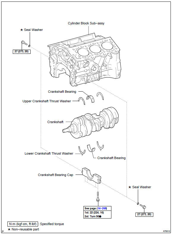
13. INSPECT CRANKSHAFT THRUST CLEARANCE
a. Using a dial indicator, measure the thrust clearance while prying the crankshaft back and forth with a screwdriver.
Specified thrust clearance: 0.04 to 0.30 mm (0.0016 to 0.0118 in.)
If the thrust clearance is greater than the maximum, replace the thrust washers as a set. Check the crankshaft for wear, repair or replace if necessary.
Thrust washer thickness: 1.93 to 1.98 mm (0.0760 to 0.0780 in.).
Inspect crankshaft thrust clearance
14. CHECK OIL CLEARANCE
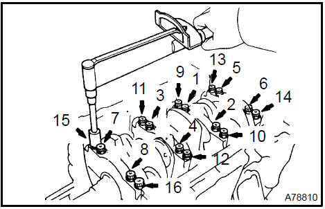
a. Uniformly loosen and remove the 8 main bearing cap bolts and seal washers in the sequence shown in the illustration.
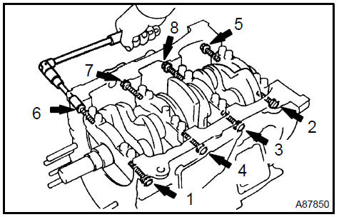
b. Uniformly loosen and remove the 16 main bearing cap bolts the sequence shown in the illustration.
c. Remove the 4 main bearing caps and 4 lower bearings.
Also remove the 2 lower thrust washers, located under the No. 2 main bearing cap.
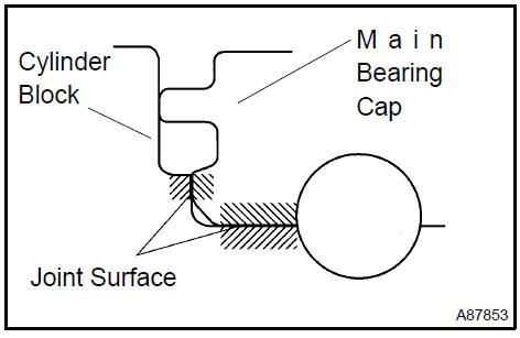
NOTICE: Using a screwdriver, push up on the cap little by little, alternating from the right and left side until the cap is free. Take care not to damage the contact surfaces of the cap and cylinder block.
HINT:
-
Keep the lower bearing and main bearing cap together.
-
Arrange the main bearing caps and lower thrust washers in correct order.
d. Lift out the crankshaft.
HINT: Keep the upper bearings together with the cylinder block.
-
Clean each main journal and bearing.
-
Check each main journal and bearing for pitting and scratches.
If the journal or bearing is damaged, replace the bearings. If necessary, replace the crankshaft.
-
Place the crankshaft on the cylinder block.
-
Lay a strip of Plastigage across each journal.
i. Install the 4 main bearing caps.
NOTICE: Do not turn the crankshaft.
j. Remove the main bearing caps (see steps a. to c.).
k. Measure the Plastigage at its widest point.
Specified oil clearance:
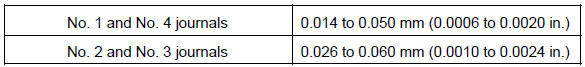
If the oil clearance is greater than the maximum, replace the bearings. If necessary, replace the crankshaft.
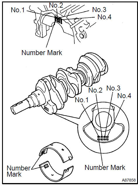
HINT: If using a bearing, replace it with one that has the same number.
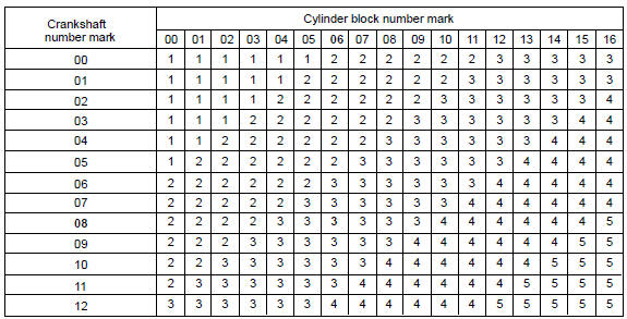
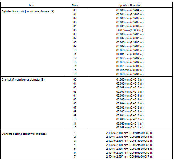
If the number of the bearing cannot be determined, select the correct bearing by adding together the numbers imprinted on the cylinder block and crankshaft, then refer to the table on the next page for the appropriate bearing number. The No. 1 and No. 4 journal bearings have 5 standard bearing sizes, marked 3, 4, 5, 6 and 7 accordingly. The No. 2 and No. 3 journal bearings have 5 standard bearing sizes, marked 1, 2, 3, 4 and 5 accordingly.
No. 1 and No. 4 journal bearings
HINT:
EXAMPLE:
Cylinder block imprinted number mark is 06
Crankshaft imprinted number mark is 08
6 + 8 = 14
Select the bearing marked ”5”
No. 1 and No. 4 journal standard bearings selection chart
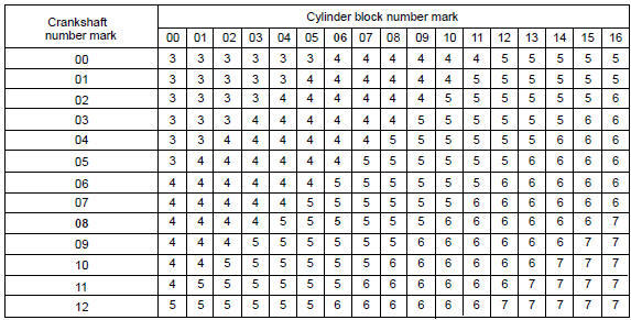
EXAMPLE: Cylinder block ”06”, Crankshaft ”08” = Use bearing ”5”
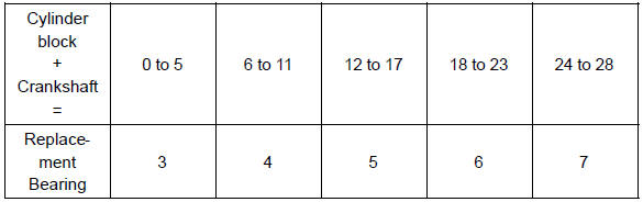
No. 2 and No. 3 journal bearings
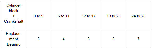
HINT:
EXAMPLE
Cylinder block imprinted number mark is 06
Crankshaft imprinted number mark is 08
6 + 8 = 14
Select the bearing marked ”3”
No.2 and No.3 journal standard bearings selection chart
EXAMPLE: Cylinder block ”06”, Crankshaft ”08” = Use bearing ”3”
Reference
l. Completely remove the Plastigage.
15. REMOVE CRANKSHAFT
-
Lift the crankshaft.
-
Remove the 4 upper main bearings and 2 upper thrust washers from the cylinder block.
HINT: Arrange the main bearing caps, bearings and thrust washers in the correct order.
-
REMOVE CRANKSHAFT THRUST WASHER SET
-
REMOVE CRANKSHAFT BEARING
-
CLEAN CYLINDER BLOCK
NOTICE: If the cylinder is washed at high temperatures, the cylinder liner sticks out beyond the cylinder block.
Always wash the cylinder block at a temperature of 45 C (113 F) or less.
19. INSPECT CYLINDER BLOCK FOR FLATNESS
a. Using a precision straight edge and feeler gauge, measure the surface contacting the cylinder head gasket for warpage.
Maximum warpage: 0.05 mm (0.0020 in.)
If the warpage is greater than the maximum, replace the cylinder block.
Inspect cylinder block for flatness
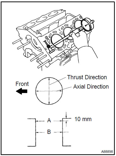
20. INSPECT CYLINDER BORE
a. Using a cylinder gauge, measure the cylinder bore diameter at positions A and B in the thrust and axial directions.
Specified diameter:
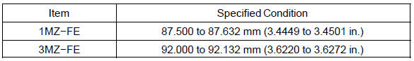
If the average of the measured diameters is greater than the maximum, replace the cylinder block.
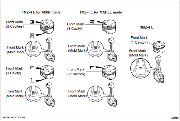
21. INSPECT W/PIN PISTON SUB−ASSY
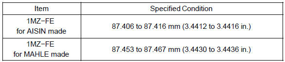
a. 1MZ−FE: Using a micrometer, measure the diameter at right angles to the piston pin center line and the distance from the piston head.
Distance:
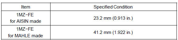
Piston diameter:
HINT: The shape of the piston varies for the RH and LH banks. The RH piston is marked with ”R”, the LH piston with ”L”.
b. 3MZ−FE: Using a micrometer, measure a diameter at right angles to the piston pin center line and the distance from the piston bottom.
Distance: 13.0 mm (0.512 in.)
Piston diameter:
91.953 to 91.967 mm (3.6202 to 3.6207 in.)
22. INSPECT PISTON OIL CLEARANCE
a. Subtract the piston diameter measurement from the cylinder bore diameter measurement.
Specified oil clearance: 0.033 to 0.130 mm (0.0013 to 0.0051 in.)
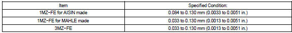
If the oil clearance is greater than the maximum, replace all the 6 pistons. If necessary, replace the cylinder block.
23. INSPECT CONNECTING ROD SUB−ASSY
a. Using a rod aligner and feeler gauge, check the connecting rod alignment.
1. Check for misalignment.
Maximum misalignment: 0.05 mm (0.0020 in.) per 100 mm (3.94 in.)
If misalignment is greater than the maximum, replace the connecting rod assembly.
2. Check for twist.
Maximum twist: 0.15 mm (0.0059 in.) per 100 mm (3.94 in.)
If the twist is greater than the maximum, replace the connecting rod assembly.
24. INSPECT PISTON PIN OIL CLEARANCE
a. Using a caliper gauge, measure the inside diameter of the connecting rod bushing.
Bushing inside diameter: 22.005 to 22.014 mm (0.8663 to 0.8667 in.)
-
Using a micrometer, measure the piston pin diameter.
Piston pin diameter: 21.997 to 22.006 mm (0.8660 to 0.8664 in.)
-
Subtract the piston pin diameter measurement from the bushing inside diameter measurement.
Specified oil clearance: 0.005 to 0.050 mm (0.0002 to 0.0020 in.)
If the oil clearance is greater than the maximum, replace the bushing. If necessary, replace the piston and the piston pin together.
25. REMOVE CONNECTING ROD SMALL END BUSH
a. Using SST and a press, press out the bushing.
SST 09222−30010
Remove connecting rod small end bush
26. INSTALL CONNECTING ROD SMALL END BUSH
a. Align the oil holes of a new bushing and the connecting rod.
b. Using SST and a press, press in the bushing.
SST 09222−30010
c. Using a pin hole grinder, hone the bushing to obtain the standard specified clearance between the bushing and piston pin.
Standard oil clearance: 0.005 to 0.011 mm (0.0002 to 0.0004 in.)
d. Check that the piston pin fits at normal room temperature.
Coat the piston pin with engine oil, and push it into the connecting rod with your thumb.
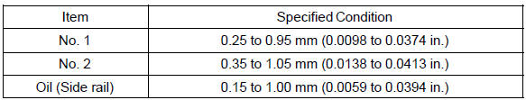
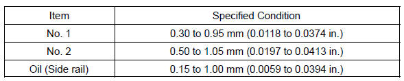
27. INSPECT RING GROOVE CLEARANCE
a. Using a feeler gauge, measure the clearance between new piston ring and the wall of the ring groove.
Ring groove clearance:
1MZ−FE
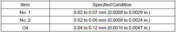
3MZ−FE:
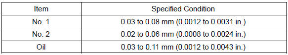
If the clearance is not as specified, replace the piston.
28. INSPECT PISTON RING END GAP
a. Using a piston, push the piston ring a little beyond the bottom of the ring travel, 110 mm (4.33 in.) from the top of the cylinder block.
b. Using a feeler gauge, measure the end gap.
Specified end gap:
1MZ−FE
3MZ−FE:
If the end gap is greater than the maximum, replace the piston ring.
If the end gap is greater than the maximum even with a new piston ring, replace the cylinder block.
29. INSPECT CONNECTING ROD BOLT
a. Using a vernier caliper, measure the tension portion diameter of the bolt.
Specified diameter: 7.2 to 7.6 mm (0.283 to 0.299 in.)
If the diameter is less than the minimum, replace the bolt.
Inspect connecting rod bolt
30. INSPECT CRANKSHAFT BEARING CAP SET BOLT
a. Using a dial indicator and V−blocks, measure the runout as shown in the illustration.
Maximum circle runout: 0.06 mm (0.0024 in.)
If the circle runout is greater than the maximum, replace the crankshaft.
Inspect crankshaft bearing cap set bolt
31. INSPECT CRANKSHAFT
a. Using a dial indicator and V−blocks, measure the runout as shown in the illustration.
Maximum circle runout: 0.06 mm (0.0024 in.)
If the circle runout is greater than the maximum, replace the crankshaft.
b. Using a micrometer, measure the diameter of each main journal.
Diameter: 60.988 to 61.000 mm (2.4011 to 2.4016 in.)
If the diameter is not as specified, check the oil clearance (see step 7).
If necessary, replace the crankshaft.
c. Check each main journal for taper and out−of−round as shown in the illustration.
Maximum taper and out−of−round: 0.02 mm (0.0008 in.)
If the taper and out−of−round is greater than the maximum, replace the crankshaft.
d. Using a micrometer, measure the diameter of each crank pin.
Diameter: 52.992 to 53.000 mm (2.0863 to 2.0866 in.)
If the diameter is not as specified, check the oil clearance (see step 7).
e. Check each crank pin for taper and out−of−round as shown in the illustration.
Maximum taper and out−of−round: 0.02 mm (0.0008 in.)
If the taper and out−of−round is greater than the maximum, replace the crankshaft.
32. INSTALL STUD BOLT
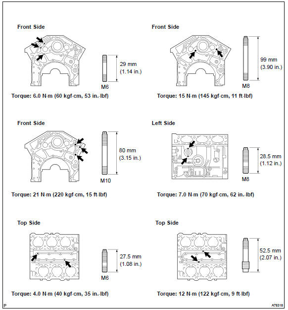
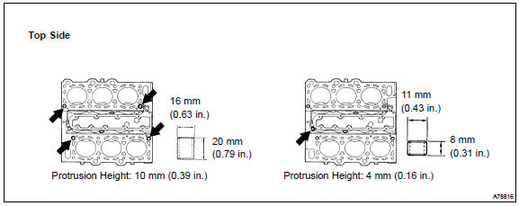
33. INSTALL STRAIGHT PIN
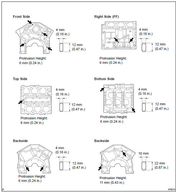
34. INSTALL RING PIN
35. INSTALL PISTON PIN HOLE SNAP RING
a. Using a small screwdriver, install a new snap ring at one end of the piston pin hole.
HINT: Be sure that the end gap of the snap ring is not aligned with the pin hole cutout portion of the piston.
Install piston pin hole snap ring
36. INSTALL W/PIN PISTON SUB−ASSY
a. Gradually heat the piston to about 80 C (176 F).

b. Coat the piston pin with engine oil.
c. Align the front marks of the piston and connecting rod, and push in the piston pin with your thumb until the pin contacts the snap ring.
37. INSTALL PISTON PIN HOLE SNAP RING
a. Using a small screwdriver, install a new snap ring on the other end of the piston pin hole.
HINT: Be sure that the end of gap of the snap ring is not aligned with the pin hole cutout portion of the piston.
Install piston pin hole snap ring
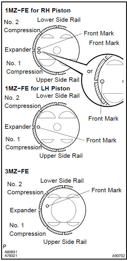
38. INSTALL PISTON RING SET
-
Install the oil ring expander and the 2 side rails by hand.
-
Using a piston ring expander, install the 2 compression rings.
HINT: The No. 1 and No. 2 compression rings are installed with code mark faced upward as shown in the illustration.
Code mark:
1MZ−FE:
3MZ−FE

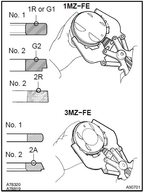
c. Position the piston rings so that the ring ends are arranged as shown in the illustration.
NOTICE: Do not align the ring ends.
39. INSTALL CONNECTING ROD BEARING
a. Align the key of the bearing with the keyway of the connecting rod or connecting cap.
NOTICE: Clean the backside of the bearing and the bearing surface of the connecting rod. The surface should be free of dust and oils.
Install connecting rod bearing
40. INSTALL CRANKSHAFT BEARING
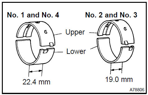
HINT: Main bearings come in width of 22.4 mm (0.882 in.) and 19.0 mm (0.748 in.). Install the 22.4mm (0.882 in.) bearings in the No. 1 and No. 4 cylinder block journal positions with the main bearing cap. Install the 19.0 mm (0.748 in.) bearings in the No.
2 and No. 3 positions.
a. Align the key of the bearing with the keyway of the cylinder block, and push in the 4 upper bearings.
NOTICE: Do not apply engine oil to the bearing and its contact surface.
b. Align the key of the bearing with the keyway of the main bearing cap, and push in the 4 lower bearings.
NOTICE: Do not apply engine oil to the bearing and its contact surface.
HINT: A number is marked on each main bearing cap to indicate the installation position.
41. INSTALL CRANKSHAFT THRUST WASHER SET
a. Install the 2 thrust washers under the No. 2 journal position of the cylinder block with the oil grooves facing outward.
b. Install the 2 thrust washers on the No. 2 bearing cap with the grooves facing outward.
42. INSTALL CRANKSHAFT
-
Apply engine oil to the upper bearing and install the crankshaft on the cylinder block.
-
Examine the front marks and numbers and install the bearing caps on the cylinder block.
-
Apply a light coat of engine oil on the threads of the bearing cap bolts.
-
Temporarily install the 8 main bearing cap bolts to the inside positions.
e. Install the main bearing cap by hand using the inner bolt as a guide. Stop the main bearing cap is about 6 mm (0.23 in.) away from contacting with the block.

-
Using a plastic−faced hammer, lightly tap the bearing cap to ensure a proper fit.
-
Apply a light coat of engine oil on the threads of the main bearing cap bolts.
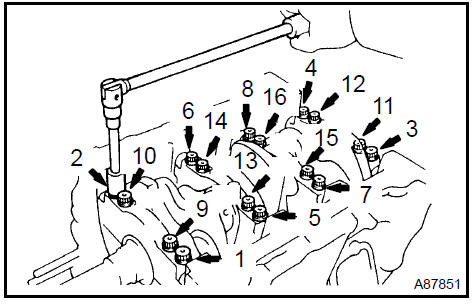
h. Uniformly install and tighten the 16 main bearing cap bolts in the sequence shown in the illustration.
Torque: 22 N·m (224 kgf·cm, 16 ft·lbf)
-
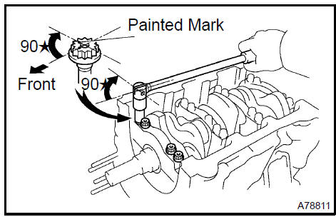
Mark the front side of the bearing cap bolts with paint.
-
Retighten the bearing cap bolts by 90 in the same sequence as step h..
-
Check that each painted mark is now at a 90 angle to the front.
-
Check that the crankshaft turns smoothly.
-
Install a new seal washer to the main bearing cap bolt
n. Uniformly install and tighten the 8 main bearing cap bolts in the sequence shown in the illustration.
Torque: 27 N·m (275 kgf·cm, 20 ft·lbf)
HINT: Use the short bolt for the marked position (arrow).
43. INSTALL PISTON SUB−ASSY W/CONNECTING ROD
-
Apply engine oil to the cylinder walls, the pistons, and the surfaces of connecting rod bearings.
-
Check the position of the piston ring ends.
-
Using a piston ring compressor, push the correctly numbered piston and connecting rod assemblies into each cylinder with the front mark of the piston facing forward.
NOTICE: Match the numbered connecting rod cap with the connecting rod.
-
Check that the protrusion of the connecting rod cap is facing the correct direction.
-
Apply a light coat of engine oil on the threads of the connecting rod cap bolts.
f. Tighten the bolts in several steps by the specified torque.
Torque: 25 N·m (250 kgf·cm, 18 ft·lbf)
-
Mark the front side of each connecting cap bolt with paint.
-
Retighten the cap bolts by 90 as shown in the illustration.
-
Check that the crankshaft turns smoothly.
44. INSTALL CYLINDER BLOCK W/HEAD STRAIGHT SCREW No.1 PLUG
a. Using a socket hexagon wrench 10, install a new gasket and the screw plug.
Torque: 30 N·m (306 kgf·cm, 22 ft·lbf)
 Install cylinder block w/head straight screw No.1 Plug
45. INSTALL CYLINDER BLOCK W/HEAD STRAIGHT SCREW No.2 PLUG
a. Using a socket hexagon wrench 10, install a new gasket and the screw plug.
Torque: 30 N·m (306 kgf·cm, 22 ft·lbf)
Install cylinder block w/head straight screw No.2 Plug
46. INSTALL CYLINDER BLOCK W/HEAD STRAIGHT SCREW No.3 PLUG
a. Using a socket hexagon wrench 10, install a new gasket and the screw plug.
Torque: 50 N·m (510 kgf·cm, 37 ft·lbf)
 Install cylinder block w/head straight screw No.3 Plug
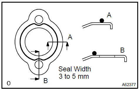
47. INSTALL WATER SEAL PLATE
a. Remove any old seal packing from the contact surface.
b. Apply a continuous bead of seal packing (diameter 3 to 5 mm (0.12 to 0.20 in.)) as shown in the illustration.
Seal packing: Part No. 08826−00100 or equivalent
NOTICE:
-
Remove any oil from the contact surface.
-
Install the seal plate within 3 minutes after applying seal packing.
-
Do not expose the seal to engine oil for at least 2 hours after installing.
c. Install the seal plate with the 2 nuts.
Torque: 18 N·m (184 kgf·cm, 13 ft·lbf)
48. INSTALL CYLINDER BLOCK WATER DRAIN COCK SUB−ASSY
a. Apply adhesive to 2 or 3 threads of the drain cock end.
Adhesive: Part No. 08833−00070, THREE BOND 1324 or equivalent
b. After applying the specified torque, rotate the drain cock clockwise as shown in the illustration.
Torque: 39 N·m (398 kgf·cm, 29 ft·lbf)
NOTICE:
-
Install the drain cock within 3 minutes after applying adhesive.
-
Do not expose the seal to coolant for at least 1 hour after installing.
-
Do not rotate the drain cock more than 1 revolution (360 ) after tightening the drain cock with the specified torque.
-
Do not loosen the drain cock after setting it correctly.
Engine (2AZ−FE) (From July, 2003)
Timing gear case or timing chain case oil seal (2AZ−FE)(From July, 2003)
Engine rear oil seal (2AZ−FE)(From July, 2003)
Cylinder head assy (2AZ−FE) (From July, 2003)
Cylinder block assy (2AZ−FE)(From July, 2003)
Engine (1MZ−FE/3MZ−FE)
Drive belt (1MZ−FE/3MZ−FE)
Valve clearance (1MZ−FE/3MZ−FE)
Partial engine assy (1MZ−FE/3MZ−FE)
Partial engine assy (2AZ−FE)(From July, 2003)
Partial engine assy (1MZ−FE/3MZ−FE)
Timing belt (1MZ−FE/3MZ−FE)
Camshaft (RH BANK) (1MZ−FE/3MZ−FE)
Camshaft (LH BANK) (1MZ−FE/3MZ−FE)
Cylinder head gasket (1MZ−FE/3MZ−FE)
Cylinder head gasket No.2 (1MZ−FE/3MZ−FE)
Oil pump seal (1MZ−FE/3MZ−FE)
Engine rear oil seal (1MZ−FE/3MZ−FE)
Cylinder head assy (1MZ−FE/3MZ−FE)
Cylinder block assy (1MZ−FE/3MZ−FE)
Partial engine assy (2AZ−FE)(From July, 2003)
Drive belt (2AZ−FE)(From July, 2003)
Valve clearance (2AZ−FE)
Chain (2AZ−FE)(From July, 2003)
Camshaft (2AZ−FE)(From July, 2003)
Cylinder head gasket (2AZ−FE)(From July, 2003)
Toyota Camry XV30 (2002–2006) Service Manual
- Introduction
- Audio & visual system
- Automatic transmission / trans
- Brake
- Clutch
- Communication system
- Cooling
- Cruise control
- Drive shaft / propeller shaft
- Emission control
- Engine control system
- Engine hood/door
- Engine mechanical
- Exhaust
- Exterior/interior trim
- Front suspension
- Fuel
- Heater & air conditioner
- Ignition
- Instrument panel/meter
- Intake
- Lighting
- Lubrication
- Manual transmission/transaxle
- Parking brake
- Power steering
- Rear suspension
- Seat
- Service specifications
- Sliding roof/convertible
- Starting & charging
- Steering column
- Supplemental restraint system
- Theft deterrent & door lock
- Tire & wheel
- Windshield/windowglass/mirror
- Wiper & washer
- Wiring
Categories
