 Toyota Camry XV30 (2002–2006) Service ManualHeater & air conditioner
Air conditioning system
Air conditioning system
ON−VEHICLE INSPECTION
1. INSPECT PRESSURE SWITCH No.1
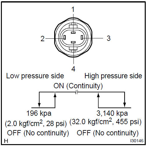
a. Magnetic clutch control: Inspect pressure switch operation.
- Set on the manifold gauge set.
- Connect the positive (+) lead from the ohmmeter to terminal 4 and the negative (−) lead to terminal 1.
- Check continuity between terminals when refrigerant
pressure is changed, as shown in the illustration.
If operation is not as specified, replace the pressure switch.
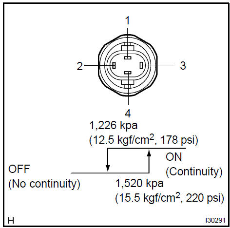
b. Cooling fan control: Inspect pressure switch operation.
- Connect the positive (+) lead from the ohmmeter to terminal 2 and the negative (−) lead to terminal 3.
- Check continuity between terminals when refrigerant pressure is changed, as shown in the illustration.
If operation is not as specified, replace the pressure switch.
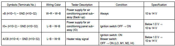
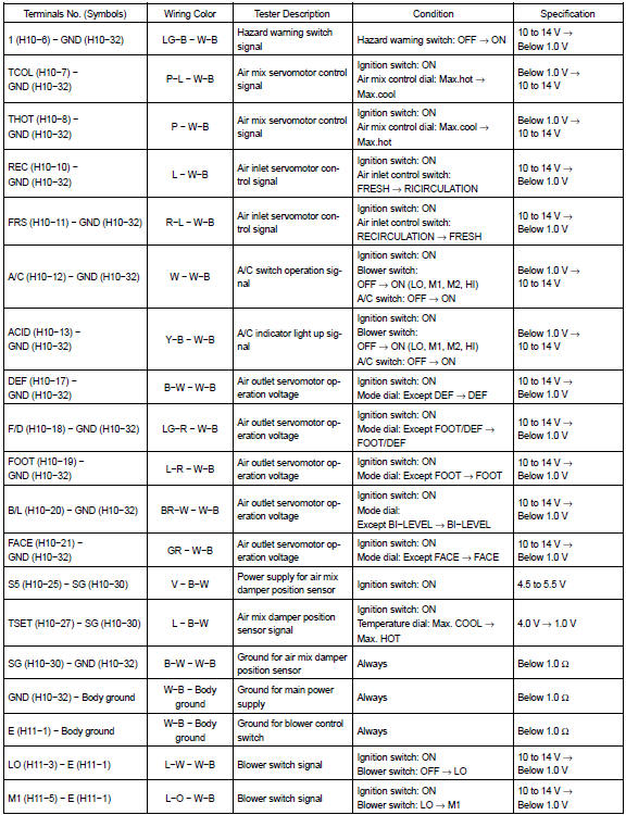
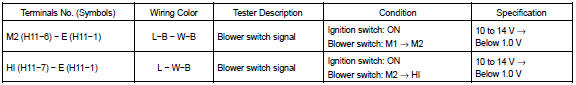
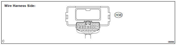
2. INSPECT AIR CONDITIONING CONTROL PANEL SUB−ASSY
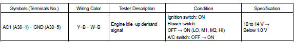
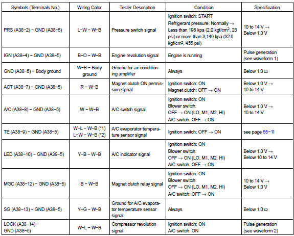
a. Disconnect the connector from controller and inspect the connector on wire harness side, as shown in the chart below.
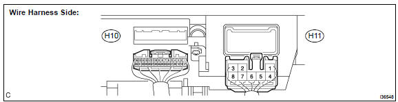
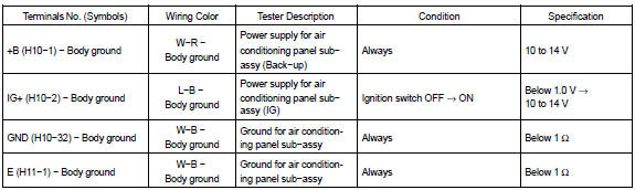
If the circuit is not as specified, inspect the circuits connected to other parts.
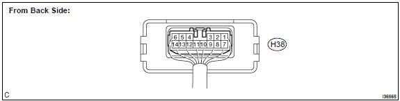
b. Connect the connector to heater controller and inspect wire harness side from the back side, as shown in the chart below.
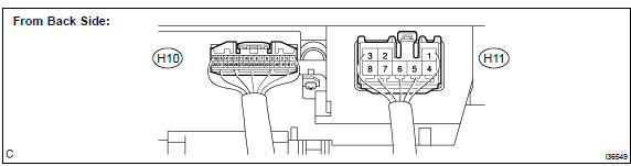
If circuit is as specified, replace the controller with a new one. If the circuit is not as specified, inspect the circuits connected to other parts.
3. INSPECT AIR CONDITIONING AMPLIFIER (2AZ−FE)
a. Disconnect the connector from controller and inspect the connector on wire harness side, as shown in the chart below.

If the circuit is not as specified, inspect the circuits connected to other parts.
b. Connect the connector to air conditioning amplifier and inspect wire harness side from the back side, as shown in the chart below.
If circuit is as specified, replace the controller with a new one. If the circuit is not as specified, inspect the circuits connected to other parts.
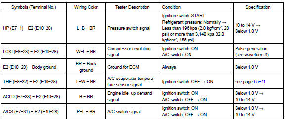
4. INSPECT ECM (1MZ−FE, 3MZ−FE)
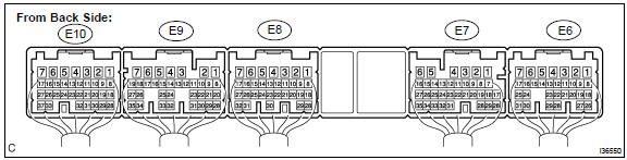
If circuit is as specified, replace the controller with a new one. If the circuit is not as specified, inspect the circuits connected to other parts.
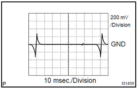
waveform 1: Measure the waveform between terminal IGN of the A/C amplifier assy connector and body ground.
OK: A waveform should be output as shown in the illustration.
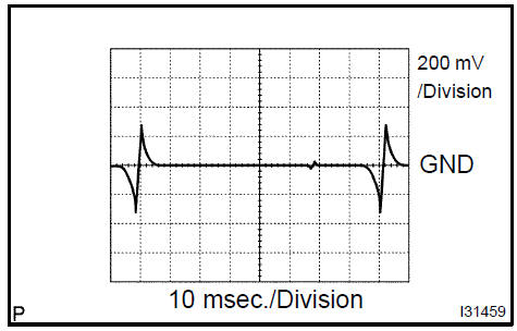
waveform 2: Measure the waveform between terminal LOCK of the A/C amplifier assy connector and body ground.
OK: A waveform should be output as shown in the illustration.
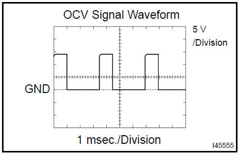
waveform 3: Measure the waveform between terminal LCKI of the ECM connector and body ground.
OK: A waveform should be output as shown in the illustration.
Air conditioning system
Refrigerant
Air conditioning system
Refrigerant
Refrigerant line
V (cooler compressor to crankshaft pulley) beltNNo.1
Air conditioner control assembly
Air conditioning panel sub-assy
Air conditioning radiator assy
Air conditioning system
Blower assy
Cooler compressor assy (3MZ−FE)
Cooler compressor assy (1MZ−FE)
Cooler compressor assy (2AZ−FE)
Cooler condenser assy
Toyota Camry XV30 (2002–2006) Service Manual
- Introduction
- Audio & visual system
- Automatic transmission / trans
- Brake
- Clutch
- Communication system
- Cooling
- Cruise control
- Drive shaft / propeller shaft
- Emission control
- Engine control system
- Engine hood/door
- Engine mechanical
- Exhaust
- Exterior/interior trim
- Front suspension
- Fuel
- Heater & air conditioner
- Ignition
- Instrument panel/meter
- Intake
- Lighting
- Lubrication
- Manual transmission/transaxle
- Parking brake
- Power steering
- Rear suspension
- Seat
- Service specifications
- Sliding roof/convertible
- Starting & charging
- Steering column
- Supplemental restraint system
- Theft deterrent & door lock
- Tire & wheel
- Windshield/windowglass/mirror
- Wiper & washer
- Wiring
Categories
