 Toyota Camry XV30 (2002–2006) Service ManualHeater & air conditioner
Cooler condenser assy
Cooler condenser assy
ON−VEHICLE INSPECTION
1. INSPECT COOLER CONDENSER ASSY
a. If a fin of the cooler condenser assy is dirty, clean it with water and dry it with compressor air.
NOTICE: Do not damage the fin of the condenser assy.
b. If a fin of the condenser assy is bent, make it straight using a screwdriver or pliers.
2. INSPECT CONDENSER FOR LEAKAGE OF REFRIGERANT
- Using a halogen leak detector, check pipe joints for gas leakage.
- If gas leakage is detected in a joint, check the torque of the joint.
COMPONENTS
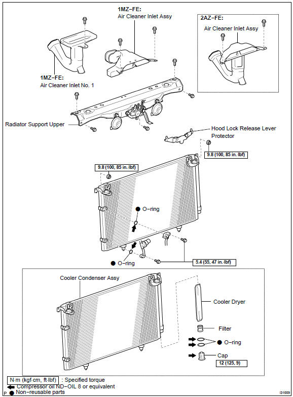
OVERHAUL
HINT: COMPONENTS
- DISCHARGE REFRIGERANT FROM REFRIGERATION SYSTEM
SST 07110−58060 (07117−58080, 07117−58090, 07117−78050, 07117−88060, 07117−88070, 07117−88080)
- REMOVE COOLER REFRIGERANT DISCHARGE HOSE No.1
- Remove the bolt and disconnect the cooler refrigerant discharge hose No. 1 from the cooler condenser assy.
- Remove the O−ring from the cooler refrigerant discharge hose No. 1.
NOTICE: Seat the opening of the disconnected parts using vinyl tape to prevent moisture and foreign matter from entering.
 Remove cooler refrigerant discharge hose No.1
3. DISCONNECT COOLER REFRIGERANT LIQUID PIPE A
- Remove the bolt and disconnect the cooler refrigerant liquid pipe A from the cooler condenser assy.
- Remove the O−ring from the cooler refrigerant liquid pipe A.
NOTICE: Seal the opening of the disconnected parts using vinyl tape to prevent moisture and foreign matter from entering.
 Disconnect cooler refrigerant liquid pipe A
- REMOVE AIR CLEANER INLET ASSY
3MZ−FE:
1MZ−FE:
2AZ−FE: - REMOVE RADIATOR SUPPORT UPPER
3MZ−FE:
1MZ−FE:
2AZ−FE: - REMOVE COOLER CONDENSER ASSY
a. Remove the 2 nuts and cooler condenser assy.
 Remove cooler condenser assy
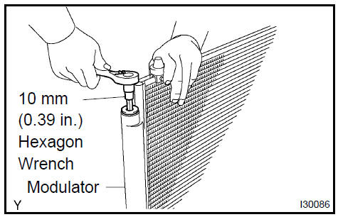
7. REMOVE COOLER DRYER
a. Using hexagon wrench 10 mm (0.39 in.), remove the cap and filter from the modulator.
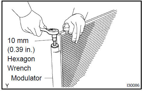
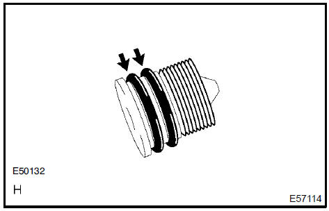
b. Remove the 2 O−rings from the cap.
c. Using a needle nose pliers, remove the cooler dryer.
SST 99999−60018
8. INSTALL COOLER DRYER
a. Using a needle nose pliers, install the cooler dryer.
- Install 2 new O−rings to the cap.
- Sufficiently apply compressor oil to the fit surfaces of the
O−ring and the cap.
Compressor oil: ND−OIL 8 or equivalent
d. Using hexagon wrench 10 mm (0.39 in.), install the cap to the cooler condenser assy.
Torque: 12 N·m (125 kgf·cm, 9 ft·lbf)
SST 99999−60018
9. INSTALL COOLER CONDENSER ASSY
a. Install the cooler condenser assy with the 2 nuts.
Torque: 9.8 N·m (100 kgf·cm, 85 in.·lbf)
 Install cooler condenser assy
10. INSTALL RADIATOR SUPPORT UPPER
3MZ−FE:
1MZ−FE:
2AZ−FE:
11. INSTALL COOLER REFRIGERANT LIQUID PIPE A
- Remove the attached vinyl tape from the tube and connecting part of the cooler condenser assy.
- Sufficiently apply compressor oil to the new O−ring and
pipe joint.
Compressor oil: ND−OIL 8 or equivalent
- Install a O−ring to the cooler refrigerant liquid pipe A.
- Connect the cooler refrigerant liquid pipe A to the cooler
condenser assy with the bolt.
Torque: 5.4 N·m (55 kgf·cm, 47 in.·lbf)
12. INSTALL COOLER REFRIGERANT DISCHARGE HOSE No.1
- Remove the attached vinyl tape from the tube and connecting part of the cooler condenser assy.
- Sufficiently apply compressor oil to the new O−ring and
hose joint.
Compressor oil: ND−OIL 8 or equivalent
- Install a O−ring to the cooler refrigerant discharge hose No. 1.
d. Connect the cooler refrigerant discharge hose No. 1 to the cooler condenser assy with the bolt.
Torque: 5.4 N·m (55 kgf·cm, 47 in.·lbf)
- CHARGE REFRIGERANT
SST 07110−58060 (07117−58060, 07117−58070, 07117−58080, 07117−58090, 07117−78050, 07117−88060, 07117−88070, 07117−88080)
Specified amount: 550 50 g (19.37 1.76 oz.)
- WARM UP ENGINE
- INSPECT LEAKAGE OF REFRIGERANT
Air conditioning system
Refrigerant
Air conditioning system
Refrigerant
Refrigerant line
V (cooler compressor to crankshaft pulley) beltNNo.1
Air conditioner control assembly
Air conditioning panel sub-assy
Air conditioning radiator assy
Air conditioning system
Blower assy
Cooler compressor assy (3MZ−FE)
Cooler compressor assy (1MZ−FE)
Cooler compressor assy (2AZ−FE)
Cooler condenser assy
Toyota Camry XV30 (2002–2006) Service Manual
- Introduction
- Audio & visual system
- Automatic transmission / trans
- Brake
- Clutch
- Communication system
- Cooling
- Cruise control
- Drive shaft / propeller shaft
- Emission control
- Engine control system
- Engine hood/door
- Engine mechanical
- Exhaust
- Exterior/interior trim
- Front suspension
- Fuel
- Heater & air conditioner
- Ignition
- Instrument panel/meter
- Intake
- Lighting
- Lubrication
- Manual transmission/transaxle
- Parking brake
- Power steering
- Rear suspension
- Seat
- Service specifications
- Sliding roof/convertible
- Starting & charging
- Steering column
- Supplemental restraint system
- Theft deterrent & door lock
- Tire & wheel
- Windshield/windowglass/mirror
- Wiper & washer
- Wiring
Categories
