 Toyota Camry XV30 (2002–2006) Service ManualPower steering
Rack & pinion power steering gear assy
Rack & pinion power steering gear assy
COMPONENTS
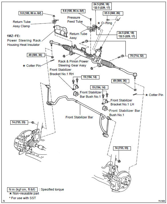
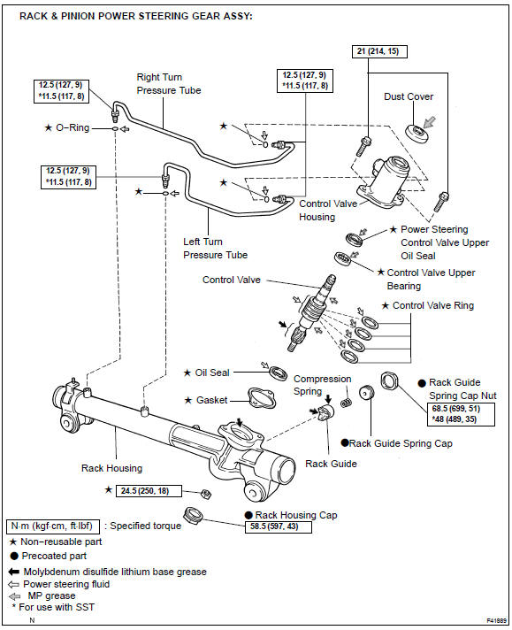
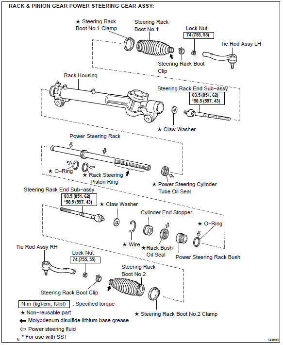
OVERHAUL
NOTICE: When installing , coat the parts indicated by the arrow with power steering fluid or molybdenum disulfide lithium base grease .
-
PRECAUTION
-
DISCONNECT BATTERY NEGATIVE TERMINAL
-
REMOVE HORN BUTTON ASSY
-
REMOVE STEERING WHEEL ASSY
SST 09950−50013 (09951−05010, 09952−05010, 09953−05020, 09954−05021)
-
REMOVE FRONT WHEEL
-
REMOVE SPIRAL CABLE SUB−ASSY
-
DISCONNECT TIE ROD ASSY LH
-
Remove the cotter pin and nut.
-
Using SST, remove the tie rod assy LH from the steering knuckle.
SST 09628−62011
 Disconnect tie rod assy LH
8. DISCONNECT TIE ROD ASSY RH
SST 09628−62011
HINT: Remove the RH side by the same procedures with LH side.
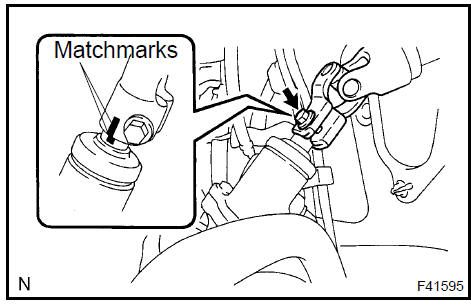
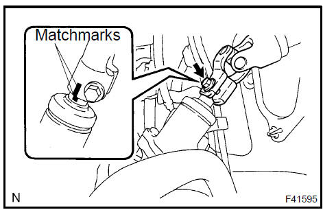
9. DISCONNECT STEERING INTERMEDIATE SHAFT SUB−ASSY
-
Loosen the bolt and remove the clamp from the steering column hole cover No.1.
-
Disconnect the steering column hole cover No.2 from the steering column hole cover No.1.
-
Loosen the bolt.
-
Place matchmarks on the steering intermediate shaft sub−assy and rack & pinion power steering gear assy.
-
Remove the bolt and separate the steering intermediate shaft sub−assy.
10. DISCONNECT FRONT STABILIZER LINK ASSY LH
a. Remove the nut and disconnect the front stabilizer link assy from the absorber.
HINT: If the ball joint turns together with the nut, use a hexagon wrench (6 mm) to hold the stud.
 Disconnect front stabilizer link assy LH
11. DISCONNECT FRONT STABILIZER LINK ASSY RH
HINT: Remove the RH side by the same procedures with LH side.
12. REMOVE FRONT STABILIZER BRACKET No.1 LH
a. Remove the 2 bolts and disconnect the front stabilizer bracket No.1 LH.
 Remove front stabilizer bracket No.1 LH
13. REMOVE FRONT STABILIZER BRACKET No.1 RH
HINT: Remove the RH side by the same procedures with LH side.
14. DISCONNECT PRESSURE FEED TUBE ASSY
a. Using SST, disconnect the return tube assy from the rack & pinion power steering gear assy.
SST 09023−12701
b. Using SST, disconnect the pressure feed tube assy from the rack & pinion power steering gear assy.
SST 09023−12701
c. Remove the nut and disconnect the return tube clamp.
15. REMOVE RACK & PINION POWER STEERING GEAR ASSY
a. Remove the bolt and disconnect the tube clamp.
b. Remove the 2 bolts, nuts and rack & pinion power steering gear assy.
16. REMOVE POWER STEERING RACK HOUSING HEAT INSULATOR (1MZ−FE ENGINE TYPE)
a. Remove the power steering rack housing heat insulator.
17. REMOVE STEERING LEFT TURN PRESSURE TUBE
-
Using SST, renove the left turn pressure tube.
SST 09023−38201
-
Remove the 2 O−rings from the left turn pressure tube.
18. REMOVE STEERING RIGHT TURN PRESSURE TUBE
-
Using SST, renove the right turn pressure tube.
SST 09023−38201
-
Remove the 2 O−rings from the right turn pressure tube.
19. FIX RACK & PINION POWER STEERING GEAR ASSY
a. Using SST, secure the rack & pinion power steering gear assy.
SST 09612−00012
HINT: Tape the SST before use.
 Fix rack & pinion power steering gear assy
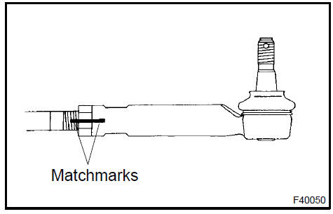
20. REMOVE TIE ROD ASSY LH
-
Place matchmarks on the tie rod assy LH and steering rack end sub−assy.
-
Loosen the lock nut, and remove the tie rod assy LH and lock nut.
 Remove tie rod assy LH
21. REMOVE TIE ROD ASSY RH
HINT: Remove the RH side by the same procedures with LH side.
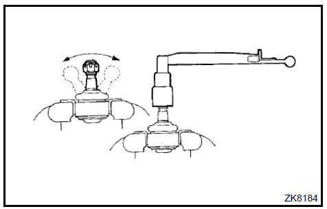
22. INSPECT TIE ROD ASSY LH
-
Secure the tie rod assy LH in a vise.
-
Install the nut to the stud bolt.
-
Flip the ball joint stud back and forth 5 times.
-
Using a torque wrench, turn the nut continuously at a rate of 3 − 5 seconds per 1 turn and take the torque reading of the 5th turn.
Turning torque: 0.83 − 3.43 N·m (8.5 − 35.0 kgf·cm, 7.3 − 30.4 in.·lbf)
 Inspect tie rod assy LH
23. INSPECT TIE ROD ASSY RH
HINT: Remove the RH side by the same procedures with LH side.
24. REMOVE STEERING RACK BOOT CLIP
a. Remove the 2 steering rack boot clips.
25. REMOVE STEERING RACK BOOT No.2 CLAMP
a. Using pliers, remove the steering rack boot No.2 clamp.
NOTICE: Be careful not to damage the steering rack boot No.2.
26. REMOVE STEERING RACK BOOT No.1 CLAMP
HINT: Remove the steering rack boot No.1 clamp by the same procedures with the steering rack boot No.2 clamp.
NOTICE: Be careful not to damage the steering rack boot No.1.
27. REMOVE STEERING RACK BOOT No.2
a. Remove the steering rack boot No.2.
28. REMOVE STEERING RACK BOOT No.1
HINT: Remove the steering rack boot No.1 by the same procedures with the steering rack boot No.2.
29. REMOVE STEERING RACK END SUB−ASSY
a. Using a screwdriver and a hammer, unstake the claw washer.
NOTICE: Avoid any impact to the power steering rack.
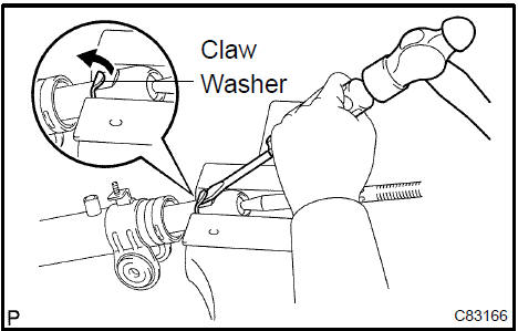
b. Using 2 SSTs, remove the 2 steering rack ends sub−assy and 2 claw washers.
SST 09922−10010
NOTICE:
-
Use SST 09922−10010 in the direction shown in the illustration.
-
Securely hold the power steering rack end with a SST.
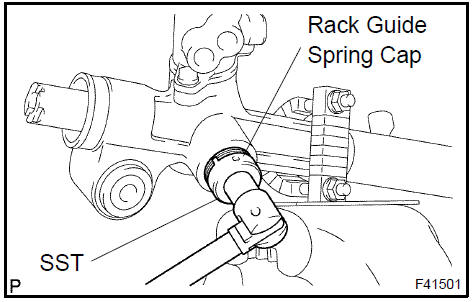
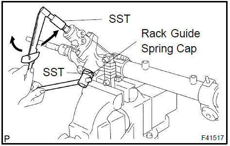
30. REMOVE RACK GUIDE
a. Using SST, remove the rack guide spring cap nut.
SST 09922−10010
NOTICE: Use SST 09922−10010 in the direction shown in the illustration.
b. Using SST, remove the rack guide spring cap.
SST 09631−10021 c. Remove the compression spring and rack guide.
31. REMOVE POWER STEERING CONTROL VALVE
a. Using a socket wrench (27 mm), remove the rack housing cap.
b. Using SST, hold the control valve and remove the nut.
SST 09616−00011
-
Wind vinyl tape around the serrated part of the control valve.
-
Remove the dust cover from the control valve housing.
-
Remove the 2 bolts and control valve.
-
Remove the gasket.
-
To prevent oil seal lip damage, wind vinyl tape around the serrated part of the control valve.
-
Using a plastic hammer, remove the control valve with oil seal from the control valve housing.
-
Remove the oil seal from the control valve.
j. Using a screwdriver, remove the 4 control valve rings.
NOTICE: Be careful not to damage the grooves for the control valve rings.
32. REMOVE POWER STEERING CONTROL VALVE UPPER OIL SEAL
a. Using SST and a press, remove the control valve upper bearing and power steering control valve upper oil seal from the control valve housing.
SST 09950−70010 (09951−07150), 09950−60010 (09951−00250)
 Remove power steering control valve upper oil seal
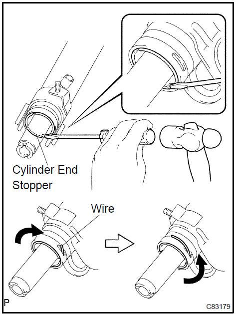
33. REMOVE CYLINDER END STOPPER
-
Using a screwdriver and a hammer, turn the cylinder end stopper clockΩise until the wire end is visible through the service hole.
-
Using a screwdriver and a hammer, turn the cylinder end stopper counterclockΩise, and remove the wire and cylinder end stopper.
 Remove cylinder end stopper
-
REMOVE POWER STEERING RACK
-
REMOVE POWER STEERING RACK BUSH
-
Remove the power steering rack bush from the power steering rack.
-
Using SST, remove the rack bush oil seal.
SST 09527−21011, 09612−24014 (09613−22011)
-
Using a screwdriver, remove the O−ring from the power steering rack bush.
 Remove power steering rack bush
36. INSPECT POWER STEERING RACK
-
Using a dial indicator, check the power steering rack for runout and for teeth wear and damage.
Maximum runout: 0.3 mm (0.012 in.)
-
Check the back surface for wear and damage.
 Inspect power steering rack
37. REMOVE POWER STEERING CYLINDER TUBE OIL SEAL
a. Using SST and a press, remove the power steering cylinder tube oil seal.
SST 09950−70010 (09951−07360), 09950−60010 (09951−00290)
 Remove power steering cylinder tube oil seal
38. REMOVE RACK STEERING PISTON RING
a. Using a screwdriver, remove the rack steering piston ring and O−ring.
NOTICE: Be careful not to damage the grooves for rack steering piston ring.
 Remove rack steering piston ring
39. INSTALL RACK STEERING PISTON RING
-
Coat a new O−ring with power steering fluid and install it to the power steering rack.
-
Expand a new rack steering piston ring with your fingers.
NOTICE: Be careful not to over expand the rack steering piston ring.
c. Coat a new rack steering piston ring with power steering fluid.
d. Install the rack steering piston ring to the power steering rack, and settle it down with your fingers.
40. INSTALL POWER STEERING CYLINDER TUBE OIL SEAL
-
Coat a new power steering cylinder tube oil seal lip with power steering fluid.
SST 09950−60010 (09951−00420, 09951−00250, 09952−06010), 09950−70010 (09951−07360)
-
Using SST and a press, install the power steering cylinder tube oil seal.
NOTICE:
-
Make sure that the power steering cylinder tube oil seal is installed facing in the correct direction.
-
Take care so that the power steering cylinder tube oil seal will not be reversed as you install it.
 Install power steering cylinder tube oil seal
41. INSTALL POWER STEERING RACK
a. Install SST to the power steering rack.
SST 09631−33010
HINT: If necessary, scrape the burrs off the power steering rack teeth end and burnish.
-
Coat the SST with power steering fluid.
-
Install the power steering rack into the rack housing.
-
Remove the SST.
 Install power steering rack
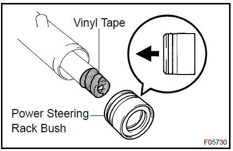
42. INSTALL POWER STEERING RACK BUSH
a. Using SST and a press, install the rack bush oil seal to the power steering rack bush.
SST 09950−60010 (09951−00400), 09950−70010 (09951−07100)
NOTICE: Make sure that the rack bush oil seal is installed facing in the correct direction.
b. Coat a new O−ring with power steering fluid and install it to the power steering rack bush.
-
To prevent rack bush oil seal lip damage, wind vinyl tape around the power steering rack end, and apply power steering fluid.
-
Install the power steering rack bush to the power steering rack.
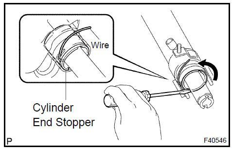
43. INSTALL CYLINDER END STOPPER
-
Align the installation hole for the wire of the cylinder end stopper with the slot of the rack housing.
-
Install a new wire into the cylinder end stopper.
-
Using a screwdriver, turn the cylinder end stopper clockΩise by 450 50 .
 Install cylinder end stopper
44. AIR TIGHTNESS TEST
-
Install SST to the rack housing.
SST 09631−12071 (09633−00010)
-
Apply vacuum of 53 kPa (400 mmHg, 15.75 in.Hg) for about 30 seconds.
-
Check that there is no change in the vacuum.
If there is a change in the vacuum, check the installation of the oil seals.
 Air tightness test
45. INSTALL POWER STEERING CONTROL VALVE UPPER OIL SEAL
-
Coat a control valve upper bearing and a new power steering control valve upper oil seal with power steering fluid.
-
Using SST and a press, install the power steering control valve upper oil seal.
SST 09950−70010 (09951−07150), 09950−60010 (09951−00180, 09952−06010, 09951−00320)
c. Using SST and a press, install the control valve upper bearing.
SST 09950−70010 (09951−07150), 09950−60010 (09951−00180, 09952−06010, 09951−00340)
46. INSTALL POWER STEERING CONTROL VALVE
a. Expand 4 new control valve rings with your fingers.
NOTICE: Be careful not to over expand the control valve ring.
-
Coat the 4 control valve rings with power steering fluid.
-
Install the 4 control valve rings to the control valve, and settle them down with your fingers.
d. Carefully slide the tapered end of SST over the control valve rings until they fit to the control valve.
SST 09631−22081
NOTICE: Be careful not to damage the control valve rings.
-
To prevent power steering control valve upper oil seal lip damage, wind vinyl tape around the serrated part of the control valve.
-
Coat the power steering control valve upper oil seal lip with power steering fluid.
-
Install the control valve to the control valve housing.
NOTICE: Be careful not to damage the control valve ring and power steering control valve upper oil seal lip.
-
Coat a new oil seal lip with power steering fluid.
-
Using SST and a press, install the oil seal.
SST 09612−22011
NOTICE: Make sure that the oil seal is installed facing in the correct direction.
-
Apply grease to the needle bearing.
-
Install a new gasket to the control valve housing.
-
Wind vinyl tape around the serration part of the control valve.
-
Install the control valve housing to the rack housing with the 2 bolts.
Torque: 21 N·m (214 kgf·cm, 15 ft·lbf)
-
Using SST, stop the control valve rotation and install a new lock nut.
Torque: 24.5 N·m (250 kgf·cm, 18 ft·lbf)
SST 09616−00011
-
Apply sealant to 2 or 3 threads of the rack housing cap.
Sealant: Part No. 08833−00080, THREE BOND 1344, LOCTITE 242 or equivalent
p. Using a socket wrench (27 mm), install the rack housing cap.
Torque: 58.5 N·m (597 kgf·cm, 43 ft·lbf)
q. Using a punch and a hummer, stake the rack housing cap and rack housing.
47. INSTALL RACK GUIDE
-
Install the rack guide.
-
Install the compression spring.
-
Apply sealant to 2 or 3 threads of the rack guide spring cap.
Sealant: Part No. 08833−00080, THREE BOND 1344, LOCTITE 242 or equivalent
-
Temporarily install the rack guide spring cap.
48. ADJUST TOTAL PRELOAD
-
To prevent the steering rack teeth from damaging the oil seal lip, temporarily install the RH and LH steering rack ends sub−assy.
-
Using SST, torque the rack guide spring cap.
SST 09631−10021 Torque: 25 N·m (254 kgf·cm, 18 ft·lbf)
c. Using SST, loosen the rack guide spring cap.
SST 09631−10021
-
Using SST, turn the control valve to the right and left 1 or 2 times.
SST 09616−00011
-
Using SST, loosen the rack guide spring cap until the compression spring is not functioning.
SST 09631−10021
-
Using SST and a torque wrench, tighten the rack guide spring cap until the preload is within specification.
SST 09616−00011, 09631−10021 Preload (turning): 1.2 − 1.5 N·m (12.2 − 15.3 kgf·cm, 10.6 − 13.3 in.·lbf)
-
Apply sealant to 2 or 3 threads of the rack guide spring cap nut.
Sealant: Part No. 08833−00080, THREE BOND 1344, LOCTITE 242 or equivalent
-
Temporarily install the rack guide spring cap nut.
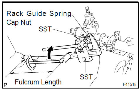
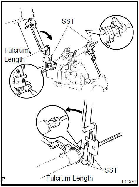
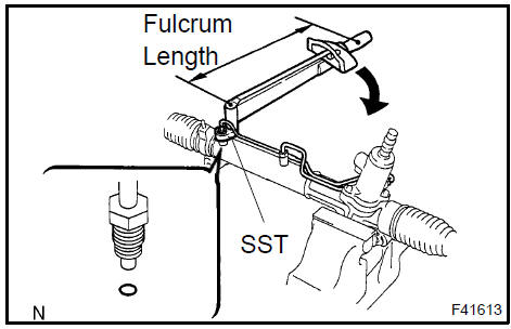
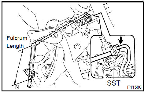
i. Using SST, hold the rack guide spring cap and using another SST, torque the rack guide spring cap nut.
SST 09616−00011, 09922−10010 Torque: 48 N·m (489 kgf·cm, 35 ft·lbf)
NOTICE: Use SST 09922−10010 in the direction shown in the illustration.
HINT: Use a torque wrench with a fulcrum length of 345 mm (13.58 in.).
-
Precheck the total preload.
Preload (turning): 1.2 − 1.5 N·m (12.2 − 15.3 kgf·cm, 10.6 − 13.3 in.·lbf)
-
Remove the RH and LH steering rack ends sub−assy.
l. Apply MP grease into the control valve, as shown in the illustration.
-
Wind vinyl tape around the serration part of the control valve.
-
Install the dust cover to the control valve housing.
49. INSTALL STEERING RACK END SUB−ASSY
a. Install a new 2 claw washers, and temporarily install the 2 steering rack ends sub−assy.
HINT: Align the claws of the claw washer with the power steering rack grooves.
b. Using 2 SSTs, install the 2 steering rack ends sub−assy.
SST 09922−10010 Torque: 58.5 N·m (597 kgf·cm, 43 ft·lbf)
NOTICE: Use SST 09922−10010 in the direction shown in the illustration.
HINT:
-
Using SST, hold the power steering rack and install the steering rack end sub−assy.
-
Use a torque wrench with a fulcrum length of 345 mm (13.58 in.).
c. Using a brass bar and a hammer, stake the claw washer.
NOTICE: Avoid any impact to the power steering rack.
50. INSPECT STEERING RACK END SUB−ASSY
a. Ensure that the steering rack end sub−assy hole is not clogged with grease.
HINT: If the hole is clogged, the pressure inside the boot will change after it is assembled and steering wheel is turned.
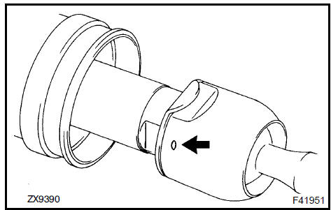 Inspect steering rack end sub-assy
51. INSTALL STEERING RACK BOOT No.2
a. Install the steering rack boot No.2.
52. INSTALL STEERING RACK BOOT No.1
HINT: Remove the steering rack boot No.1 by the same procedures with steering rack boot No.2.
53. INSTALL STEERING RACK BOOT No.2 CLAMP
a. Using SST, tighten the steering rack boot No.2 clamp, as shown in the illustration.
SST 09521−24010 Clearance: 3.0 mm (0.118 in.) or less
NOTICE: Be careful not to damage the boot No.2.
54. INSTALL STEERING RACK BOOT No.1 CLAMP
SST 09521−24010
NOTICE: Be careful not to damage the boot No.1.
HINT: Install the steering rack boot No.1 clamp by the same procedures with steering rack boot No.2 clamp.
55. INSTALL STEERING RACK BOOT CLIP
a. Using pliers, install the 2 steering rack boot clips.
56. INSTALL TIE ROD ASSY LH
a. Screw the lock nut and tie rod assy LH onto the steering rack end sub−assy until the matchmarks are aligned.
HINT: After adjusting toe−in, torque the lock nut.
57. INSTALL TIE ROD ASSY RH
HINT: Install the RH side by the same procedures with LH side.
58. INSTALL STEERING LEFT TURN PRESSURE TUBE
-
Coat 2 new O−rings with power steering fluid and install them to the left turn pressure tube.
-
Using SST, install the left turn pressure tube to the rack & pinion power steering gear assy.
SST 09023−38201 Torque: 11.5 N·m (117 kgf·cm, 8 ft·lbf)
HINT:
-
Use a torque wrench with a fulcrum length of 345 mm (13.58 in.).
-
This torque value is effective in the case that SST is parallel to a torque wrench.
59. INSTALL STEERING RIGHT TURN PRESSURE TUBE
-
Coat 2 new O−rings with power steering fluid and install them to the right turn pressure tube.
-
Using SST, install the right turn pressure tube to the rack & pinion power steering gear assy.
SST 09023−38201 Torque: 11.5 N·m (117 kgf·cm, 8 ft·lbf)
HINT:
-
Use a torque wrench with a fulcrum length of 345 mm (13.58 in.).
-
This torque value is effective in the case that SST is parallel to a torque wrench.
 Install steering right turn pressure tube
60. INSTALL POWER STEERING RACK HOUSING HEAT INSULATOR (1MZ−FE ENGINE TYPE)
a. Install power steering rack housing heat insulator.
HINT: Install nut when installing the return tube clamp.
61. INSTALL RACK & PINION POWER STEERING GEAR ASSY
a. Install the rack & pinion power steering gear assy with the 2 bolts and nuts.
Torque: 70 N·m (714 kgf·cm, 52 ft·lbf)
b. Connect the tube clamp with the bolt.
Torque: 9.8 N·m (100 kgf·cm, 86 in.·lbf)
62. CONNECT PRESSURE FEED TUBE ASSY
a. Using SST, connect the pressure feed tube assy to the rack & pinion power steering gear assy.
SST 09023−12701 Torque: 22.5 N·m (229 kgf·cm, 17 ft·lbf)
HINT:
-
Use a torque wrench with a fulcrum length of 300 mm (11.81 in.).
-
This torque value is effective in the case that SST is parallel to a torque wrench.
b. Using SST, connect the return tube assy to the rack & pinion power steering gear assy.
SST 09023−12701 Torque: 22.5 N·m (229 kgf·cm, 17 ft·lbf)
HINT:
-
Use a torque wrench with a fulcrum length of 300 mm (11.81 in.).
-
This torque value is effective in the case that SST is parallel to a torque wrench.
c. Install the return tube clamp with the nut.
Torque: 9.8 N·m (100 kgf·cm, 86 in.·lbf)
63. INSTALL FRONT STABILIZER BRACKET No.1 LH
a. Install the front stabilizer bracket No. 1 LH with the 2 bolts.
Torque: 19 N·m (194 kgf·cm, 14 ft·lbf)
 Install front stabilizer bracket No.1 LH
64. INSTALL FRONT STABILIZER BRACKET No.1 RH
HINT:
Install the RH side by the same procedures with LH side.
65. CONNECT FRONT STABILIZER LINK ASSY LH
a. Connect the stabilizer link assy LH to the stabilizer bar with the nut.
Torque: 74 N·m (755 kgf·cm, 55 ft·lbf)
HINT: If the ball joint turns together with the nut, use a hexagon wrench (6 mm) to hold the stud.
 Connect front stabilizer link assy LH
66. CONNECT FRONT STABILIZER LINK ASSY RH
HINT: Connect the RH side by the same procedures with LH side.
67. CONNECT STEERING INTERMEDIATE SHAFT SUB−ASSY
-
Align the matchmarks on the intermediate shaft sub−assy and rack & pinion power steering gear assy.
-
Install the bolt.
Torque: 35.3 N·m (360 kgf·cm, 26 ft·lbf)
-
Tighten the bolt.
Torque: 35.3 N·m (360 kgf·cm, 26 ft·lbf)
-
Install the steering column hole cover No.2 to the steering hole cover No.1.
-
Connect the clamp to the steering column hole cover No.1 and tighten the bolt.
68. CONNECT TIE ROD ASSY LH
-
Connect the tie rod assy LH with the nut.
Torque: 49 N·m (500 kgf·cm, 36 ft·lbf)
-
Install a new cotter pin.
NOTICE: If the holes for a new cotter pin are not aligned, tighten the nut further up 60 .
69. CONNECT TIE ROD ASSY RH
HINT: Connect the RH side by the same procedures with LH side.
-
INSTALL FRONT WHEEL Torque: 103 N·m (1,050 kgf·cm, 76 ft·lbf)
-
ADD POWER STEERING FLUID
-
BLEED POWER STEERING FLUID
-
CHECK POWER STEERING FLUID LEAKAGE
-
INSTALL SPIRAL CABLE SUB−ASSY
-
CENTER SPIRAL CABLE
-
INSTALL STEERING WHEEL ASSY
-
INSTALL HORN BUTTON ASSY
-
INSPECT AND ADJUST FRONT WHEEL ALIGNMENT
-
INSPECT STEERING WHEEL CENTER POINT
-
INSPECT SRS WARNING LIGHT
Power steering system
Vane pump assy (1MZ−FE/3MZ−FE)
Power steering system
Rack & pinion power steering gear assy
Power steering system
Vane pump assy (2AZ−FE)
Toyota Camry XV30 (2002–2006) Service Manual
- Introduction
- Audio & visual system
- Automatic transmission / trans
- Brake
- Clutch
- Communication system
- Cooling
- Cruise control
- Drive shaft / propeller shaft
- Emission control
- Engine control system
- Engine hood/door
- Engine mechanical
- Exhaust
- Exterior/interior trim
- Front suspension
- Fuel
- Heater & air conditioner
- Ignition
- Instrument panel/meter
- Intake
- Lighting
- Lubrication
- Manual transmission/transaxle
- Parking brake
- Power steering
- Rear suspension
- Seat
- Service specifications
- Sliding roof/convertible
- Starting & charging
- Steering column
- Supplemental restraint system
- Theft deterrent & door lock
- Tire & wheel
- Windshield/windowglass/mirror
- Wiper & washer
- Wiring
Categories
