 Toyota Camry XV30 (2002–2006) Service ManualPower steering
Vane pump assy (1MZ−FE/3MZ−FE)
Vane pump assy (1MZ−FE/3MZ−FE)
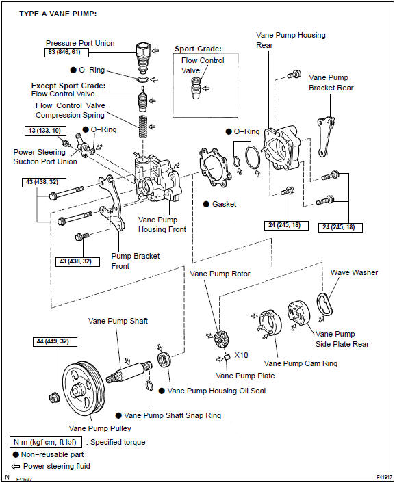
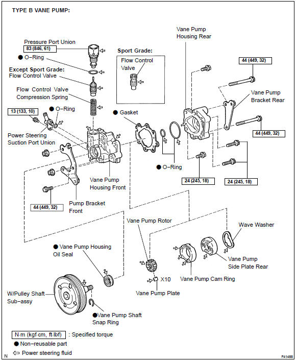
COMPONENTS
OVERHAUL
NOTICE:
-
When using a vise, do not over tighten.
-
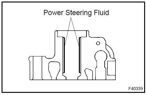
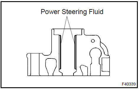
When installing, coat the parts indicated by the arrows with power steering fluid
-
REMOVE FRONT WHEEL RH
-
DRAIN POWER STEERING FLUID
-
REMOVE FRONT FENDER LINER RH
-
REMOVE FRONT FENDER APRON SEAL RH
-
DISCONNECT OIL RESERVOIR TO PUMP HOSE No.1
a. Remove the clip and disconnect the oil reservoir to pump hose No.1.
NOTICE: Take care not to spill fluid on the V belt.
6. REMOVE POWER STEERING OIL PRESSURE SWITCH
-
Disconnect the connector.
-
Remove the power steering oil pressure switch from the union bolt.
NOTICE: Be careful not to drop the power steering oil pressure switch.
If the power steering oil pressure switch is dropped or strongly damaged, replace it with a new one.
7. DISCONNECT PRESSURE FEED HOSE
a. Using a spanner (24 mm) to hold the pressure port union, remove the union bolt and gaske
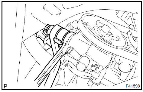 Disconnect pressure feed hose
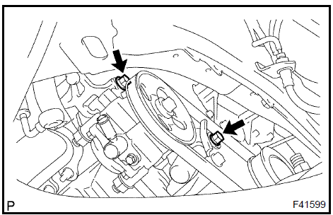
8. REMOVE VANE PUMP V BELT
a. Loosen the 2 bolts and remove the vane pump V belt.
9. REMOVE VANE PUMP ASSY
a. Remove the 2 bolts and vane pump assy.
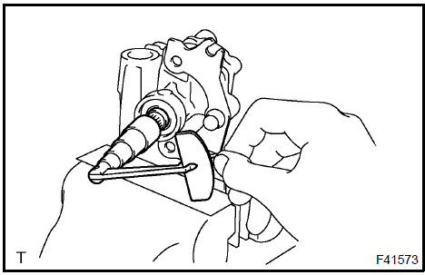
10. REMOVE VANE PUMP PULLEY (TYPE A VANE PUMP)
-
Using SST, stop the vane pump pulley rotation and loosen the nut.
SST 09960−10010 (09962−01000, 09963−01000)
-
Remove the nut and vane pump pulley from the vane pump shaft.
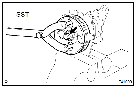 Remove vane pump pulley (type a vane pump)
11. REMOVE POWER STEERING SUCTION PORT UNION
-
Remove the bolt and power steering suction port union.
-
Remove the O−ring from the power steering suction port union.
12. REMOVE PRESSURE PORT UNION
-
Remove the pressure port union.
-
Remove the O−ring from the pressure port union.
-
REMOVE FLOW CONTROL VALVE
-
REMOVE FLOW CONTROL VALVE COMPRESSION SPRING
-
REMOVE VANE PUMP BRACKET REAR (TYPE A VANE PUMP)
a. Remove the 2 bolts, vane pump bracket rear from the vane pump assy.
16. REMOVE VANE PUMP BRACKET REAR (TYPE B VANE PUMP)
a. Remove the 2 bolts and 2 nuts, vane pump bracket rear from the vane pump assy.
17. REMOVE VANE PUMP HOUSING REAR
-
Remove the 4 bolts and vane pump housing rear from the vane pump housing front.
-
Remove the gasket.
-
Remove the 2 O−rings from the vane pump housing rear.
18. REMOVE VANE PUMP SIDE PLATE REAR
-
Remove the wave washer from the vane pump side plate rear.
-
Remove the vane pump side plate rear.
-
REMOVE VANE PUMP CAM RING
-
REMOVE VANE PUMP ROTOR
-
Remove the 10 vane pump plates from the vane pump rotor.
-
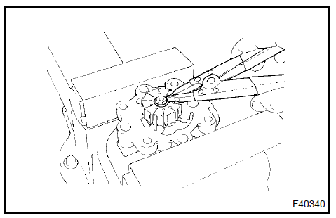
Using a screwdriver, remove the vane pump shaft snap ring from the vane pump shaft.
-
Remove the vane pump rotor.
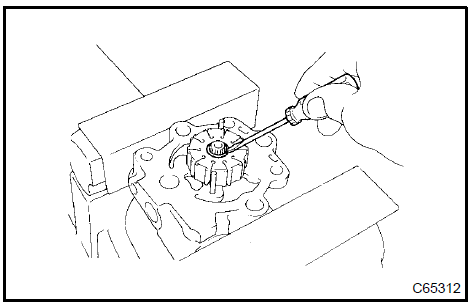 Remove vane pump rotor
-
REMOVE VANE PUMP SHAFT (TYPE A VANE PUMP)
-
REMOVE W/PULLEY SHAFT SUB−ASSY (TYPE B VANE PUMP)
-
REMOVE PUMP BRACKET FRONT
a. Remove the bolt, pump bracket front from the vane pump housing front.
24. REMOVE VANE PUMP HOUSING OIL SEAL
a. Using SST and a hammer, tap out the vane pump housing oil seal from the vane pump housing front.
SST 09631−10030
NOTICE: Be careful not to damage the bushing of the vane pump housing front.
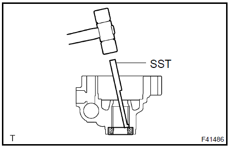 Remove vane pump housing oil seal
25. INSPECT OIL CLEARANCE
a. Using a micrometer and a caliper gauge, measure the oil clearance.
Standard clearance: 0.027 − 0.054 mm (0.00106 − 0.00213 in.) Maximum clearance: 0.07 mm (0.0028 in.)
If it is more than the maximum, replace the vane pump assy.
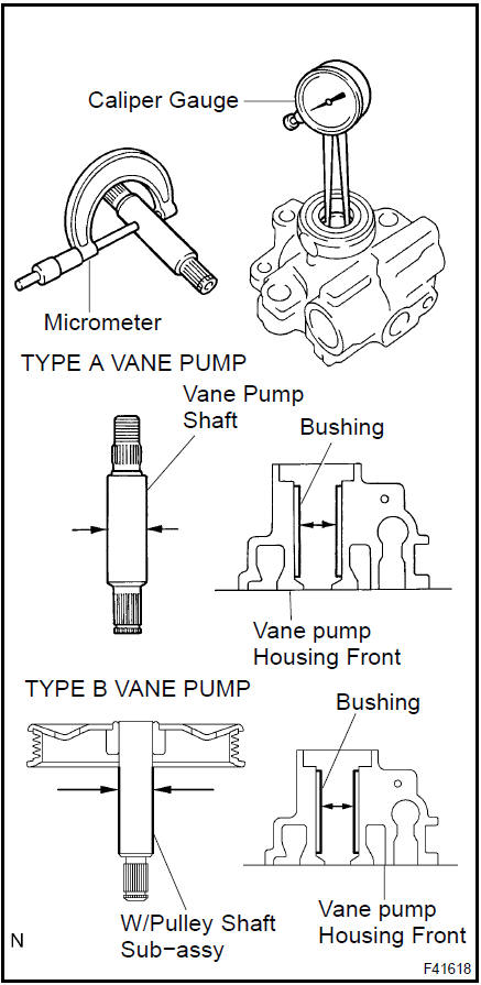 Inspect oil clearance
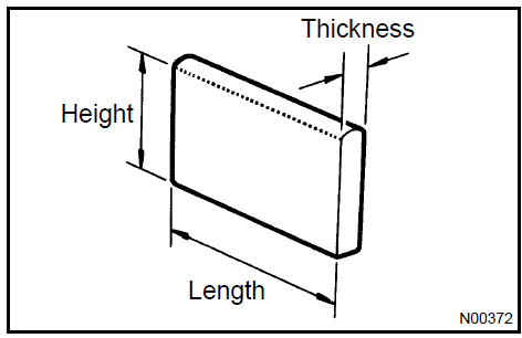
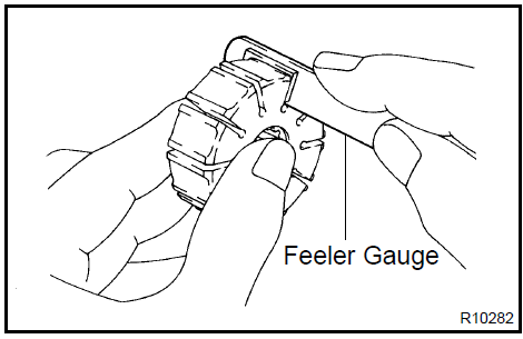
26. INSPECT VANE PUMP ROTOR AND VANE PUMP PLATES
a. Using a micrometer, measure the height, thickness and length of the vane pump plates.
Minimum height: 8.7 mm (0.343 in.) Minimum thickness: 1.4 mm (0.055 in.) Minimum length: 14.991 mm (0.59020 in.)
b. Using a feeler gauge, measure the clearance between the vane pump rotor groove and vane pump plate.
Maximum clearance: 0.03 mm (0.0012 in.)
If it is more than the maximum, replace the vane pump assy.
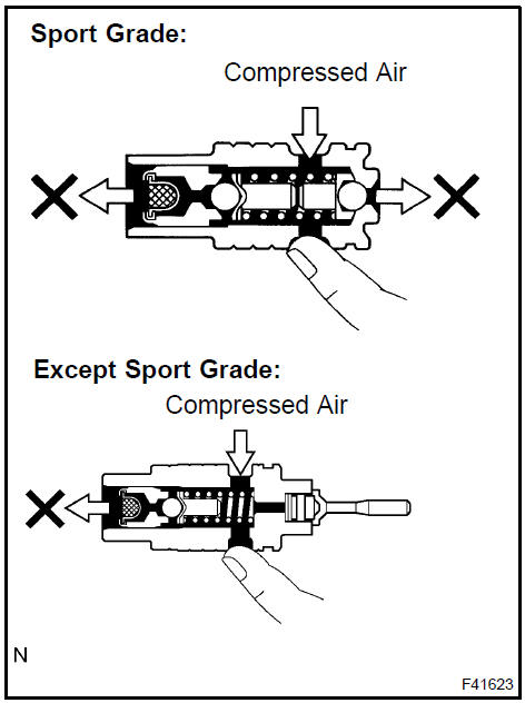
27. INSPECT FLOW CONTROL VALVE
a. Coat the flow control valve with power steering fluid and check that it falls smoothly into the flow control valve hole by its own weight.
b. Check the flow control valve for leakage. Close one of the holes and apply compressed air of 392 − 490 kPa (4 − 5 kgf/cm2, 57 − 71 psi) into the opposite side hole, and confirm that air does not come out from the end holes.
If necessary, replace the vane pump assy.
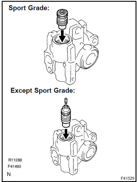
28. INSPECT FLOW CONTROL VALVE COMPRESSION SPRING
a. Using vernier calipers, measure the free length of the flow control valve compression spring.
Minimum free length: 32.24 mm (1.2693 in.) If it is not within the specification, replace the vane pump assy.
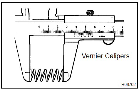 Inspect flow control valve compression spring
29. INSPECT PRESSURE PORT UNION
If the union seat in the pressure port union is remarkably damaged and it may cause fluid leakage, replace the vane pump assy.
30. INSTALL VANE PUMP HOUSING OIL SEAL
-
Coat a new vane pump housing oil seal lip with power steering fluid.
-
Using SST and a press, install the new vane pump housing oil seal.
SST 09950−60010 (09951−00330), 09950−70010 (09951−07100)
NOTICE: Make sure that the vane pump housing oil seal is installed facing the correct direction.
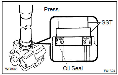 Install vane pump housing oil seal
31. INSTALL PUMP BRACKET FRONT
a. Install the pump bracket front with the bolt.
Torque: Type A Vane Pump: 43 N·m (438 kgf·cm, 32 ft·lbf) Type B Vane Pump: 44 N·m (449 kgf·cm, 32 ft·lb
f)
32. INSTALL VANE PUMP SHAFT (TYPE A VANE PUMP)
-
Coat inside bushing surface of the vane pump housing front with power steering fluid.
-
Gradually insert the vane pump shaft from the pulley side.
NOTICE: Do not damage the vane pump housing oil seal lip in the vane pump housing front.
 Install vane pump shaft (type a vane pump)
33. INSTALL W/PULLEY SHAFT SUB−ASSY (TYPE B VANE PUMP)
-
Coat inside bushing surface of the vane pump housing front with power steering fluid.
-
Gradually insert the w/pulley shaft sub−assy from the pulley side.
NOTICE: Do not damage the vane pump housing oil seal lip in the vane pump housing front.
 Install W/pulley shaft sub-assy (type b vane pump)
34. INSTALL VANE PUMP ROTOR
-
Install the vane pump rotor.
-
Using a shaft snap ring expander, install a new vane pump shaft snap ring to the vane pump shaft.
 Install vane pump rotor
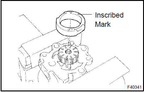
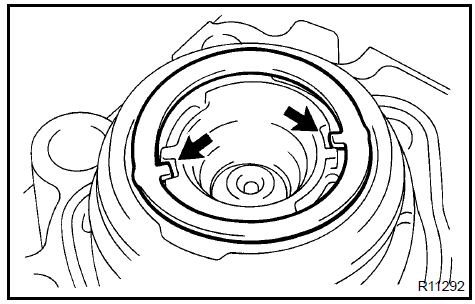
35. INSTALL VANE PUMP CAM RING
a. Align the holes of the vane pump cam ring with 2 straight pins, and install the vane pump cam ring with inscribed mark facing outward.
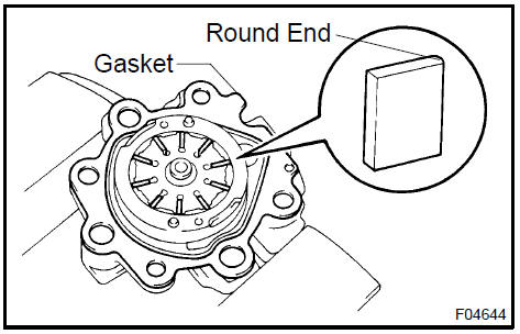
-
Coat 10 vane pump plates with power steering fluid.
-
Install the vane pump plates with the round end facing outward.
-
Install a new gasket.
36. INSTALL VANE PUMP SIDE PLATE REAR
-
Coat a new O−ring with power steering fluid and install it to the vane pump side plate rear.
-
Align the groove of the vane pump cam ring with that of the vane pump side plate rear, install the vane pump side plate rear.
c. Install the wave washer so that its protrusions fit into the slots in the vane pump side plate rear.
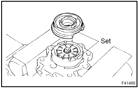
37. INSTALL VANE PUMP HOUSING REAR
-
Coat a new O−ring with power steering fluid and install it to the vane pump housing rear.
-
Install the vane pump housing rear with the 4 bolts.
Torque: 24 N·m (245 kgf·cm, 18 ft·lbf)
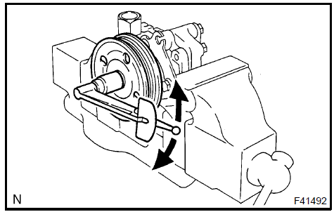
38. MEASURE VANE PUMP ROTATION TORQUE (TYPE A VANE PUMP)
-
Check that the vane pump rotates smoothly without abnormal noise.
-
Temporarily install the pulley set nut.
-
Using a torque wrench, check the vane pump rotating torque.
Rotating torque: 0.27 N·m (2.8 kgf·cm, 2.4 in.·lbf) or less
 Measure vane pump rotation torque (type a vane pump)
39. MEASURE VANE PUMP ROTATION TORQUE (TYPE B VANE PUMP)
-
Check that the vane pump rotates smoothly without abnormal noise.
-
Temporarily install the service bolt.
Recommended service bolt: Thread diameter: 10 mm (0.39 in.) Thread pitch: 1.25 mm (0.0492 in.) Bolt length: 50 mm (1.97 in.)
-
Using a torque wrench, check the vane pump rotating torque.
Rotating torque: 0.27 N·m (2.8 kgf·cm, 2.4 in.·lbf) or less
 Measure vane pump rotation torque (type b vane pump)
40. INSTALL VANE PUMP BRACKET REAR (TYPE A VANE PUMP)
a. Install the vane pump bracket rear with the 2 bolts.
Torque: 43 N·m (438 kgf·cm, 32 ft·lbf)
41. INSTALL VANE PUMP BRACKET REAR (TYPE B VANE PUMP)
a. Install the vane pump bracket rear with the 2 bolts and 2 nuts.
Torque: 44 N·m (449 kgf·cm, 32 ft·lbf)
42. INSTALL FLOW CONTROL VALVE COMPRESSION SPRING
a. Coat the flow control valve compression spring with power steering fluid and install it.
43. INSTALL FLOW CONTROL VALVE
-
Coat the flow control valve with power steering fluid.
-
Install the flow control valve.
44. INSTALL PRESSURE PORT UNION
-
Coat a new O−ring with power steering fluid and install it to the pressure port union.
-
Install the pressure port union.
Torque: 83 N·m (846 kgf·cm, 61 ft·lbf)
45. INSTALL POWER STEERING SUCTION PORT UNION
-
Coat a new O−ring with power steering fluid and install it to the power steering suction port union.
-
Install the power steering suction port union with the bolt.
Torque: 13 N·m (133 kgf·cm, 10 ft·lbf)
46. INSTALL VANE PUMP PULLEY (TYPE A VANE PUMP)
-
Install the vane pump pulley to the vane pump shaft.
-
Using SST, stop the vane pump pulley rotation and install the nut.
SST 09960−10010 (09962−01000, 09963−01000) Torque: 44 N·m (449 kgf·cm, 32 ft·lbf)
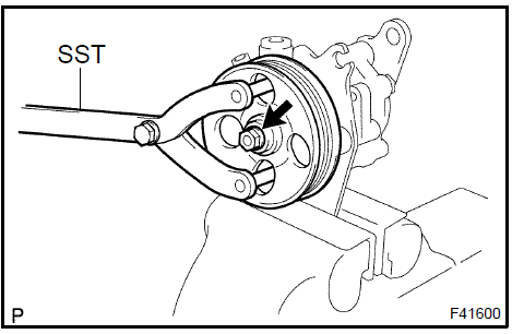 Install vane pump pulley (type a vane pump
47. INSTALL VANE PUMP ASSY
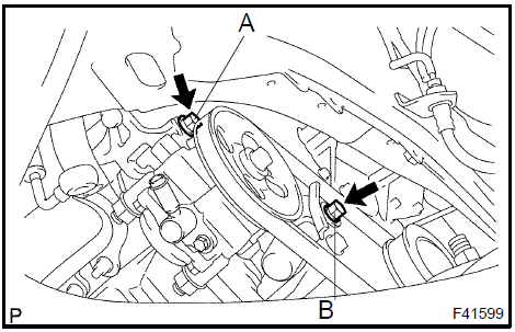
a. Temporarily install the vane pump assy with the 2 (A and B) bolts.
48. INSTALL VANE PUMP V BELT
-
Install the vane pump V belt and adjust the V belt tension.
-
Torque the bolt A.
Torque: 43 N·m (438 kgf·cm, 32 ft·lbf)
-
Torque the bolt B.
Torque: 43 N·m (438 kgf·cm, 32 ft·lbf)
 Install vane pump v belt
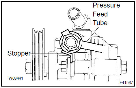
49. CONNECT PRESSURE FEED HOSE
a. Using a spanner (24 mm) to hold the pressure port union, connect the pressure feed tube assy with the union bolt and a new gasket.
Torque: 51.5 N·m (525 kgf·cm, 38 ft·lbf)
HINT: Make sure the stopper of the pressure feed tube touches the front bracket as shown in the illustration, then install the union bolt.
 Connect pressure feed hose
50. INSTALL POWER STEERING OIL PRESSURE SWITCH
a. Install the power steering oil pressure switch to the union bolt.
Torque: 21 N·m (214 kgf·cm, 15 ft·lbf)
NOTICE: Be careful not to prevent oil from being attached to the connector.
b. Connect the connector.
51. CONNECT OIL RESERVOIR TO PUMP HOSE No.1
-
Connect the oil reservoir to pump hose No.1.
-
Install the clip.
-
INSTALL FRONT FENDER APRON SEAL RH
-
INSTALL FRONT FENDER LINER RH
-
INSTALL FRONT WHEEL RH Torque: 103 N·m (1,050 kgf·cm, 76 ft·lbf)
-
BLEED POWER STEERING FLUID
-
INSPECT FLUID LEA
Power steering system
Vane pump assy (1MZ−FE/3MZ−FE)
Power steering system
Rack & pinion power steering gear assy
Power steering system
Vane pump assy (2AZ−FE)
Toyota Camry XV30 (2002–2006) Service Manual
- Introduction
- Audio & visual system
- Automatic transmission / trans
- Brake
- Clutch
- Communication system
- Cooling
- Cruise control
- Drive shaft / propeller shaft
- Emission control
- Engine control system
- Engine hood/door
- Engine mechanical
- Exhaust
- Exterior/interior trim
- Front suspension
- Fuel
- Heater & air conditioner
- Ignition
- Instrument panel/meter
- Intake
- Lighting
- Lubrication
- Manual transmission/transaxle
- Parking brake
- Power steering
- Rear suspension
- Seat
- Service specifications
- Sliding roof/convertible
- Starting & charging
- Steering column
- Supplemental restraint system
- Theft deterrent & door lock
- Tire & wheel
- Windshield/windowglass/mirror
- Wiper & washer
- Wiring
Categories
