 Toyota Camry XV30 (2002–2006) Service ManualEngine control system
Knock (1MZ−FE/3MZ−FE)
Knock (1MZ−FE/3MZ−FE)
REPLACEMENT
-
DISCHARGE FUEL SYSTEM PRESSURE
-
DRAIN ENGINE COOLANT
-
REMOVE V−BANK COVER SUB−ASSY
-
REMOVE AIR CLEANER CAP SUB−ASSY
-
REMOVE EMISSION CONTROL VALVE SET
-
REMOVE INTAKE AIR SURGE TANK
-
REMOVE INTAKE MANIFOLD
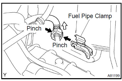
a. Disconnect the fuel pipe No. 1.
-
Remove the fuel pipe clamp.
-
Pinch the tube connector and then pull out the fuel pipe No. 1.
NOTICE:
-
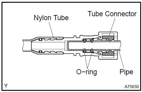
Check the connector for dirt, mud or other contamination. Clean if necessary.
-
Be sure to keep the tube connector, pipe and O−ring clean. They can become contaminated easily.
-
Do not use tools when disconnecting the fuel pipe.
-
Do not bend or twist the nylon tube. Protect the connector by covering it with a vinyl or plastic bag.
-
When the pipe and the connector are stuck, push and pull the connector to release it. Then pull the connector out carefully.
-
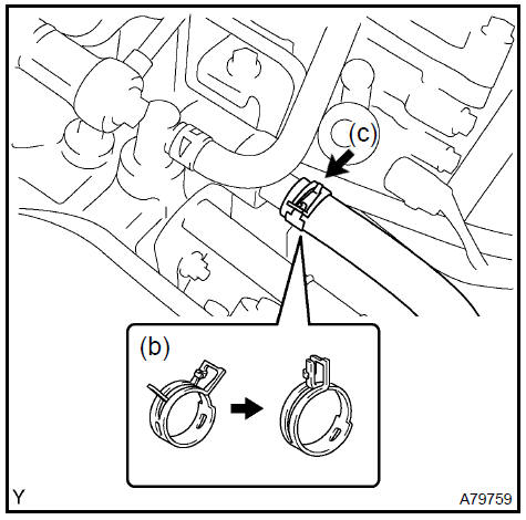
Lock the hose clamp, as shown in the illustration.
-
Disconnect the heater inlet water hose.
-
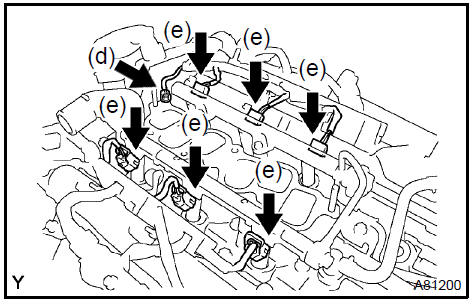
Remove the nut and disconnect the ground cable.
-
Disconnect the 6 fuel injector connectors.
-
Loosen and remove the intake manifold’s 9 bolts and 2 nuts little by little in the numerical order shown in the illustration.
-
Remove the intake manifold.
NOTICE: Fully removing each bolt and nut one by one may damage the intake manifold, bolts and nuts.
8. REMOVE WATER OUTLET
a. Disconnect the radiator hose inlet.
-
Disconnect the ECT connector.
-
Remove the clamp.
-
Remove the 2 bolts, 2 nuts and 2 washers.
-
Lock the hose clamp as shown in the illustration. Then remove the water outlet together with the water bypass hose No. 1.
-
Remove the 2 gaskets from the 2 cylinder heads.
9. REMOVE KNOCK (1MZ−FE ENGINE TYPE)
-
Disconnect the 2 knock connectors.
-
Using SST, remove the 2 knock s.
SST 09249−63010, 09816−30010
Remove knock (1MZ-FE engine type
10. REMOVE KNOCK (3MZ−FE ENGINE TYPE)
-
Disconnect the 2 knock connectors.
-
Remove the 2 nuts and 2 knock s.
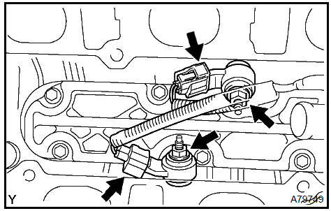
Remove knock (3MZ-FE engine type)
11. INSTALL KNOCK (1MZ−FE ENGINE TYPE)
-
Using SST, install the 2 knock s.
SST 09249−63010, 09816−30010 Torque: 39 N·m (398 kgf·cm, 29 ft·lbf)
-
Connect the 2 knock s.
 Install knock (1MZ-FE engine type)
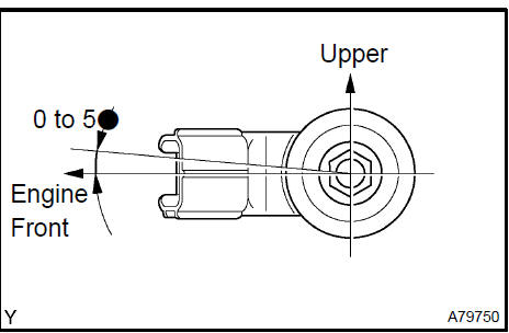
12. INSTALL KNOCK (3MZ−FE ENGINE TYPE)
-
Install the 2 knock s with the 2 nuts, as shown in the illustration.
Torque: 20 N·m (199 kgf·cm, 14 ft·lbf)
-
Connect the 2 knock connectors.
13. INSTALL WATER OUTLET
-
Install 2 new gaskets to the 2 cylinder heads.
-
Install the water outlet together with the water bypass hose No. 1 and unlock the hose clamp.
-
Tighten the 2 bolts, 2 nuts and 2 washers.
Torque: 15 N·m (153 kgf·cm, 11 ft·lbf)
-
Install the clamp.
-
Connect the ECT connector.
-
Connect the radiator hose inlet.
14. INSTALL INTAKE MANIFOLD
a. Tighten the intake manifolds’s 9 bolts and 2 nuts little by little in the numerical order shown in the illustration.
Torque: 15 N·m (153 kgf·cm, 11 ft·lbf)
NOTICE: In this case, fully tightening one of these bolts or nuts without partially tightening the other bolts or nuts in the group may damage the intake manifold, bolts and nuts.
-
Retighten the water outlet mounting bolts and nuts.
Torque: 15 N·m (153 kgf·cm, 11 ft·lbf)
-
Install the ground cable with the nut.
Torque: 8.4 N·m (86 kgf·cm, 74 in.·lbf)
-
Connect the heater inlet water hose.
e. Connect the fuel pipe No. 1.
1. Push the quick connector into the pipe until it makes ”click” sound.
NOTICE:
-
Check if there is any damage or contamination on the connected part.
-
After connecting, confirm that the connector and pipe are securely connected by trying to pull them apart.
2. Install the fuel pipe clamp.
-
INSTALL INTAKE AIR SURGE TANK
-
INSTALL EMISSION CONTROL VALVE SET
-
INSTALL AIR CLEANER CAP SUB−ASSY
-
CHECK CONNECTION OF VACUUM HOSE
-
ADD ENGINE COOLANT
-
CHECK FOR ENGINE COOLANT LEAKS
-
CHECK FOR FUEL LEAKS
-
INSTALL V−BANK COVER SUB−ASSY
SFI system (2AZ−FE)
Accelerator pedal assy (2AZ−FE)
SFI system (1MZ−FE/3MZ−FE)
Throttle body assy (1MZ−FE/3MZ−FE)
SFI system (2AZ−FE)
Knock (1MZ−FE/3MZ−FE)
ECM (1MZ−FE/3MZ−FE)
Accelerator pedal assy (1MZ−FE/3MZ−FE)
Throttle body assy (2AZ−FE)
Knock (2AZ−FE)
ECM (2AZ−FE)
Toyota Camry XV30 (2002–2006) Service Manual
- Introduction
- Audio & visual system
- Automatic transmission / trans
- Brake
- Clutch
- Communication system
- Cooling
- Cruise control
- Drive shaft / propeller shaft
- Emission control
- Engine control system
- Engine hood/door
- Engine mechanical
- Exhaust
- Exterior/interior trim
- Front suspension
- Fuel
- Heater & air conditioner
- Ignition
- Instrument panel/meter
- Intake
- Lighting
- Lubrication
- Manual transmission/transaxle
- Parking brake
- Power steering
- Rear suspension
- Seat
- Service specifications
- Sliding roof/convertible
- Starting & charging
- Steering column
- Supplemental restraint system
- Theft deterrent & door lock
- Tire & wheel
- Windshield/windowglass/mirror
- Wiper & washer
- Wiring
Categories
