 Toyota Camry XV30 (2002–2006) Service ManualCooling
Radiator assy (1MZ−FE/3MZ−FE)
Radiator assy (1MZ−FE/3MZ−FE)
ON−VEHICLE CLEANING
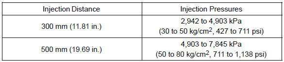
1. INSPECT FINS BLOCKAGE
a. If the fins are clogged, wash them with water or a steam cleaner. Dry with compressed air.
NOTICE:
-
If the distance between the steam cleaner and the core is too close, the fins may become damaged.
Keep the following injection distance.
Standard:
-
If the fins are bent, straighten them with a screwdriver or pliers.
-
Never apply water directly onto the electronic components.
COMPONENTS
REPLACEMENT
-
DRAIN ENGINE COOLANT
-
DISCONNECT BREATHER HOSE
-
DISCONNECT RADIATOR HOSE INLET
-
DISCONNECT RADIATOR HOSE OUTLET
-
DISCONNECT OIL COOLER OUTLET HOSE No.2
-
DISCONNECT OIL COOLER OUTLET HOSE No.3
-
REMOVE AIR CLEANER INLET ASSY
a. Remove the 3 bolts, 2 air cleaner inlets.
 Remove air cleaner inlet assy
8. REMOVE RADIATOR SUPPORT UPPER
-
Disconnect the 2 horn connectors.
-
Remove the hood lock release lever cover.
-
Remove the bolt shown in the illustration.
-
Remove the 4 bolts and radiator support upper.
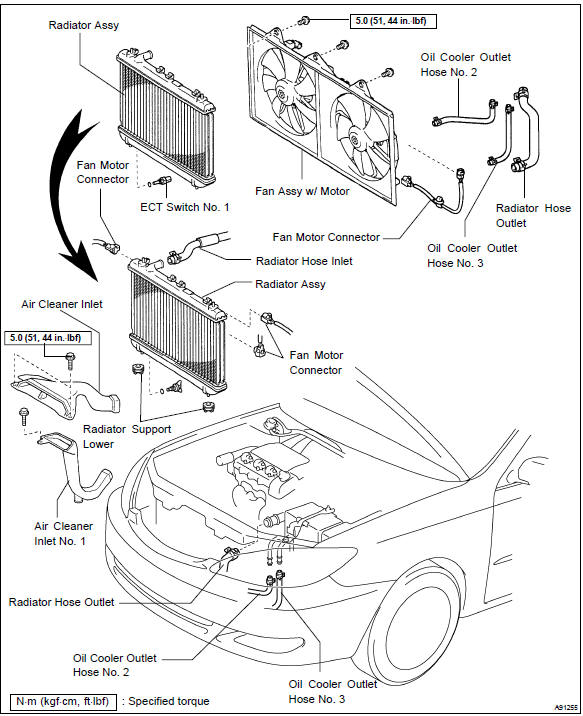
9. REMOVE RADIATOR ASSY
-
Disconnect the fan motor connector.
-
Disconnect the ECT switch No. 1 connector.
-
Remove the radiator from the body.
-
REMOVE RADIATOR SUPPORT LOWER
-
REMOVE FAN ASSY W/MOTOR
a. Remove the 3 bolts and fan w/ motor from the radiator.
12. INSTALL FAN ASSY W/MOTOR
a. Install the fan w/ motor to the radiator with the 3 bolts.
Torque: 5.0 N·m (51 kgf·cm, 44 in.·lbf)
13. INSTALL RADIATOR ASSY
-
Install the radiator to the body.
-
Connect the ECT switch No. 1 connector.
-
Connect the fan motor connector.
14. INSTALL RADIATOR SUPPORT UPPER
-
Install the radiator support upper with the 4 bolts.
Torque: 14 N·m (142 kgf·cm,10 ft·lbf)
-
Connect the 2 horn connectors.
15. INSTALL AIR CLEANER INLET ASSY
a. Install the 2 air cleaner inlets with the 3 bolts.
Torque: 5.0 N·m (51 kgf·cm, 44 in.·lbf)
 Install air cleaner inlet assy
-
ADJUST HOOD SUB−ASSY
-
ADD ENGINE COOLANT
-
CHECK FOR ENGINE COOLANT LEAKS
OVERHAUL
1. REMOVE DRAIN PLUG
-
Remove the drain plug.
-
Remove the O−ring.
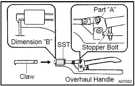
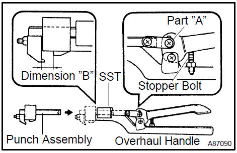
2. ASSEMBLE SST
SST 09230−01010 (09231−01010, 09231−01030)
-
Install the claw to the overhaul handle, inserting it in the hole in part ”A” as shown in the illustration.
-
While gripping the handle, adjust the stopper bolt so that dimension ”B” is as shown in the illustration.
Dimension: 0.2 to 0.3 mm (0.008 to 0.012 in.)
NOTICE: If the stopper bolt is not adjusted, the claw may be damaged.
Assemble SST
3. REMOVE UNCAULK LOCK PLATE
Using SST to release the caulking, grip the handle until stopped by the stopper bolt.
SST 09230−01010 (09231−01010, 09231−01030)
Remove uncaulk lock plate
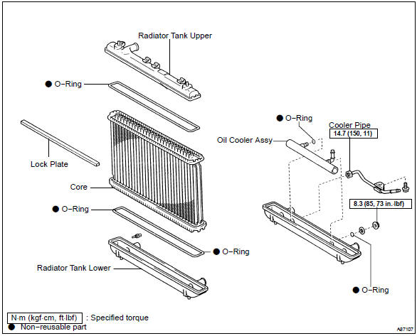
4. REMOVE RADIATOR TANK UPPER AND TANK LOWER
-
Lightly tap the bracket of the radiator (or radiator hose inlet or outlet) with a soft−faced hammer and remove the tank.
-
Remove the O−ring.
Remove radiator tank upper and tank lower
5. REMOVE OIL COOLER ASSY
-
Remove the screw and pipe.
-
Remove the nut and plate washer.
-
Remove the oil cooler.
-
Remove the 2 O−rings from the oil cooler.
Remove oil cooler assy
6. INSTALL OIL COOLER ASSY
-
Clean the O−ring contact surface of the lower tank and oil cooler.
-
Install 2 new O−rings 1. to the oil cooler 2..
-
Install the oil cooler to the lower tank 3..
-
Install the plate washer 4. and nut 5..
Torque: 8.3 N·m (85 kgf·cm, 73 in.·lbf)
-
Install the pipe 6..
Torque: 14.7 N·m (150 kgf·cm, 11 ft·lbf)
-
Install the screw 7..
Install oil cooler assy
7. INSPECT LOCK PLATE FOR DAMAGE
Inspect the lock plate for damage.
HINT:
-
If the sides of the lock plate groove are deformed, reassembly of the tank will be impossible.
Therefore, correct any deformation with pliers or similar object first.
-
Water leakage will result if the bottom of the lock plate groove is damaged or dented. Repair or replace if necessary.
NOTICE: The radiator can only be recaulked 2 times. After the 2nd time, the radiator core must be replaced.
Inspect lock plate for damage
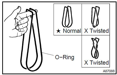
8. INSTALL RADIATOR TANK UPPER AND TANK LOWER
a. After checking that there are no foreign objects in the lock plate groove, install a new O−ring without twisting it.
HINT: When cleaning the lock plate groove, lightly rub it with sand paper without scratching it.
-
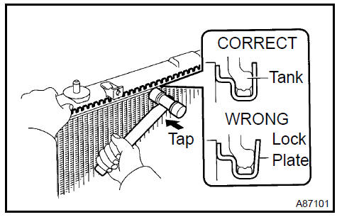
Install the tank without damaging the O−ring.
-
Tap the lock plate with a soft−faced hammer so that there is no gap between the lock plate and the tank.
9. ASSEMBLE SST
SST 09230−01010, 09231−14010
-
Install the punch assembly to the overhaul handle, inserting it in the hole in part ”A” as shown in the illustration.
-
While gripping the handle, adjust the stopper bolt so that dimension ”B” shown in the illustration.
Dimension ”B”: 8.4 mm (0.331 in.)
Assemble SST
10. CAULK LOCK PLATE
a. Lightly press SST against the lock plate in the order shown in the illustration. After repeating this a few times, fully caulk the lock plate by gripping the handle until stopped by the stopper plate.
SST 09230−01010
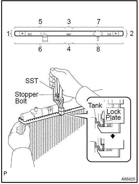
HINT:
-
Do not tap the areas protruding around the pipes, brackets or tank ribs.
-
The points shown in the illustration and oil cooler near here cannot be tapped with the SST. Use pliers or similar objects and be careful not to damage the core plates.
b. Check the lock plate height h. after completing the caulking.
Plate height h.: 7.40 to 7.80 mm (0.2913 to 0.3071 in.)
If not within the specified height, adjust the stopper bolt of the handle again and caulk again.
11. INSTALL DRAIN PLUG
-
Install a new O−ring to the drain plug.
-
Install the drain plug.
12. INSPECT FOR WATER LEAKS
-
Plug the inlet and outlet pipes of the radiator with SST.
SST 09230−01010
-
(Using a radiator cap tester, apply pressure to the radiator.
Test pressure: 177 kPa (1.8 kgf/cm2, 26 psi)
-
Submerge the radiator in water.
d. Inspect for leaks.
HINT: On radiators with resin tanks, there is a clearance between the tank and lock plate where a minute amount of air will remain, giving the appearance of an air leak when the radiator is submerged in water. Therefore, before doing the water leak test, swish the radiator around in the water first until all air bubbles disappear.
Cooling system (2AZ−FE)(From July, 2003)
Water pump assy (2AZ−FE)(From July, 2003)
Thermostat (2AZ−FE)(From July, 2003)
Radiator assy (2AZ−FE)(From July, 2003)
Cooling system (2AZ−FE)(From July, 2003)
Cooling system (1MZ−FE/3MZ−FE)
Cooling fan system (1MZ−FE/3MZ−FE)
Coolant (1MZ−FE/3MZ−FE)
Water pump assy (1MZ−FE/3MZ−FE)
Thermostat (1MZ−FE/3MZ−FE)
Radiator assy (1MZ−FE/3MZ−FE)
Cooling fan system (2AZ−FE)(From July, 2003)
Coolant (2AZ−FE)(From July, 2003)
Water pump assy (2AZ−FE)(From July, 2003)
Toyota Camry XV30 (2002–2006) Service Manual
- Introduction
- Audio & visual system
- Automatic transmission / trans
- Brake
- Clutch
- Communication system
- Cooling
- Cruise control
- Drive shaft / propeller shaft
- Emission control
- Engine control system
- Engine hood/door
- Engine mechanical
- Exhaust
- Exterior/interior trim
- Front suspension
- Fuel
- Heater & air conditioner
- Ignition
- Instrument panel/meter
- Intake
- Lighting
- Lubrication
- Manual transmission/transaxle
- Parking brake
- Power steering
- Rear suspension
- Seat
- Service specifications
- Sliding roof/convertible
- Starting & charging
- Steering column
- Supplemental restraint system
- Theft deterrent & door lock
- Tire & wheel
- Windshield/windowglass/mirror
- Wiper & washer
- Wiring
Categories
