 Toyota Camry XV30 (2002–2006) Service ManualAutomatic transmission / trans
Automatic transaxle assy (U250E)
Automatic transaxle assy (U250E)
COMPONENTS
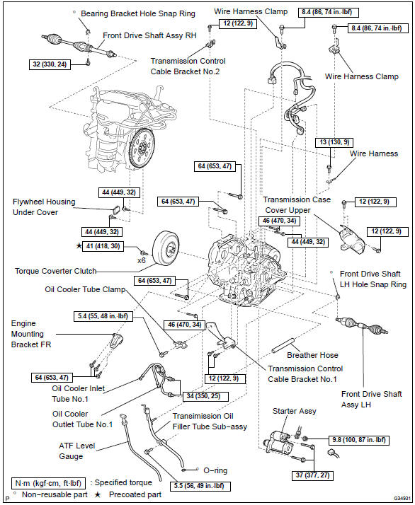 Components
REPLACEMENT
- REMOVE ENGINE ASSEMBLY WITH TRANSAXLE
- REMOVE FRONT DRIVE SHAFT ASSY RH
- REMOVE FRONT DRIVE SHAFT ASSY LH
SST 09520−01010, 09520−24010 (09520−32040)
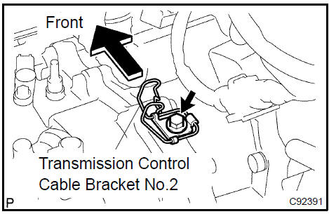
4. REMOVE TRANSMISSION CONTROL CABLE BRACKET No.2
- Remove the bolt and transmission control cable bracket No.2.
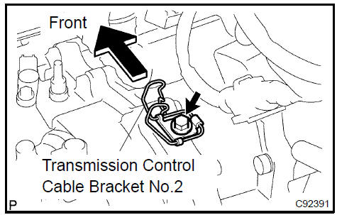
Remove transmission control cable bracket No.2
5. REMOVE WIRE HARNESS CLAMP
- Disconnect the wire harnesses from the 2 clamps.
- Remove the 2 bolts and 2 clamps.
Remove wire harness clamp
6. DISCONNECT WIRE HARNESS
- Remove the bolt and disconnect the wire harness.
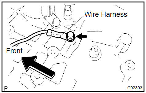
Disconnect wire harness
7. REMOVE STARTER ASSY
- Remove the nut and disconnect the starter wire.
- Disconnect the connector.
- Remove the 2 bolts and starter assy.
Remove starter assy
8. DISCONNECT CONNECTOR
- Disconnect the transmission wire connector.
- Disconnect the park/neutral position switch connector.
- Disconnect the 2 speed connectors.
- Disconnect the speedometer driven gear connector.
Disconnect connector
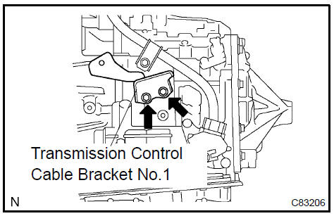
9. REMOVE TRANSMISSION CONTROL CABLE BRACKET No.1
- Remove the bolt and oil cooler tube clamp.
- Remove the 2 bolts and transmission control cable bracket No.1.
Remove transmission control cable bracket No.1
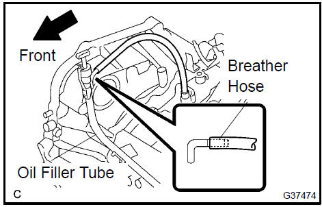
10. REMOVE TRANSMISSION OIL FILLER TUBE SUB−ASSY
- Remove the ATF level gauge.
- Remove the breather hose from the automatic transaxle.
- Remove the bolt and transmission oil filler tube sub−assy.
- Remove the O−ring from the oil filler tube.
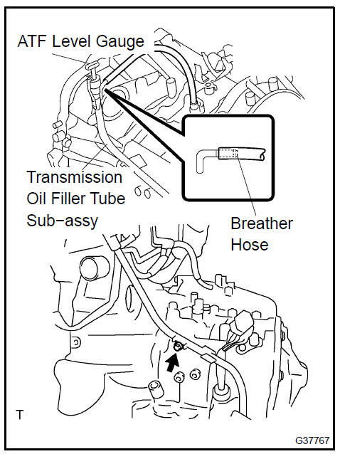 Remove transmission oil filler tube sub-assy
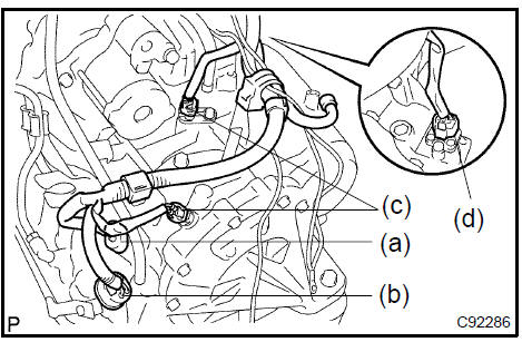
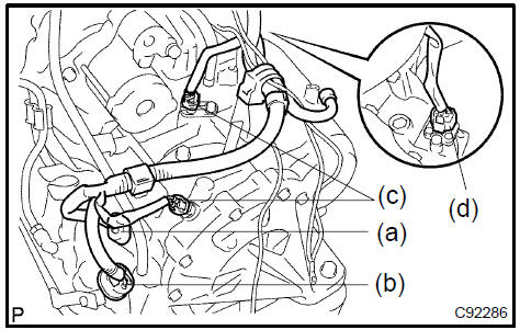
11. REMOVE OIL COOLER INLET TUBE No.1
- Remove the oil cooler inlet tube No.1.
Remove oil cooler inlet tube No.1
12. REMOVE OIL COOLER OUTLET TUBE No.1
- Remove the oil cooler outlet tube No.1.
13. REMOVE ENGINE MOUNTING BRACKET FR
- Remove the 3 bolts and engine mounting bracket FR.
 Remove engine mounting bracket FR
14. REMOVE FLYWHEEL HOUSING UNDER COVER
- Remove the flywheel housing under cover.
Remove flywheel housing under cover
15. REMOVE AUTOMATIC TRANSAXLE ASSY
- Turn the crankshaft to gain access and remove the 6 bolts while holding the crankshaft pulley bolt with a wrench.
HINT: There will be one green colored bolt.
- remove the 8 bolts.
- separate and remove the automatic transaxle.
- REMOVE TORQUE CONVERTER CLUTCH ASSY
- INSPECT TORQUE CONVERTER CLUTCH ASSY
SST 09350−32014 (09351−32010, 09351−32020)
18. REMOVE TRANSAXLE CASE COVER UPPER
- Remove the 3 bolts and transmission case cover upper.
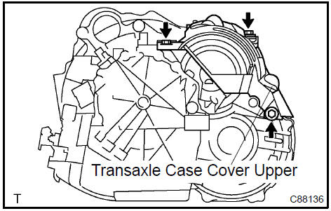
Remove transaxle case cover upper
19. INSTALL TRANSAXLE CASE COVER UPPER
- Install the transmission case cover upper with the 3 bolts.
Torque: 12 N·m (122 kgf·cm, 9 ft·lbf)
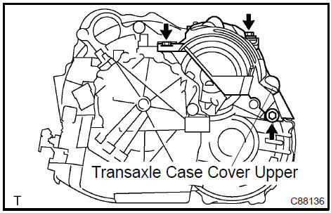 Install transaxle case cover upper
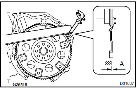
20. INSTALL TORQUE CONVERTER CLUTCH ASSY
- Using vernier calipers and a straight edge, measure the dimension ”A” between the transaxle fitting part of the engine and the converter fitting part of the drive plate.
- Set the key of the front oil pump drive gear to the top and put a mark on the housing.
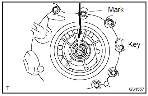
- Put a mark on the torque converter clutch so that its groove can be clearly indicated.
- Match the 2 marks on the transaxle case and the torque converter clutch and fit the splined part of the input shaft to the spline part of the turbine runner.
- Rotating the torque converter clutch, fit the spline part of
the stator shaft with the spline part of the stator.
HINT: Rotate it about 180 degrees.
- Rotating the torque converter clutch, match the 2 marks on the case and the torque converter clutch again and fit the key of the oil pump drive gear into the key way of the torque converter clutch.
NOTICE: When rotating the torque converter clutch, do not push it by excessive force.
- Using vernier calipers and a straight edge, measure the
dimension B shown in the illustration and check that B is
greater than A measured in step a.
Standard: A + 1 mm (0.04 in.) or more
21. INSTALL AUTOMATIC TRANSAXLE ASSY
- Install the automatic transaxle to the engine with the 8
bolts.
Torque: Bolt A: 64 N·m (653 kgf·cm, 47 ft·lbf) Bolt B: 44 N·m (449 kgf·cm, 32 ft·lbf) Bolt C: 46 N·m (470 kgf·cm, 34 ft·lbf)
- Apply a few drops of adhesive to 2 threads on the tip of
the 6 torque converter clutch mounting bolts.
Adhesive: Part No. 08833−00070, THREE BOND 1324 or equivalent
- Install the 6 torque converter clutch mounting bolts.
Torque: 41 N·m (418 kgf·cm, 30 ft·lbf)
NOTICE: First install the green colored bolt and then the remaining 5 bolts.
22. INSTALL FLYWHEEL HOUSING UNDER COVER
- Install the flywheel housing under cover.
Install flywheel housing under cover
23. INSTALL ENGINE MOUNTING BRACKET FR
- Install the engine mounting bracket FR with the 3 bolts to
the automatic transaxle.
Torque: 64 N·m (653 kgf·cm, 47 ft·lbf)
 Install engine mounting bracket FR
24. INSTALL TRANSMISSION OIL FILLER TUBE SUB−ASSY
- Coat a new O−ring with ATF, and install it to the oil filler tube.
- Install the oil filler tube to the automatic transaxle with the
bolt.
Torque: 5.5 N·m (56 kgf·cm, 49 in.·lbf)
- Install the breather hose to the automatic transaxle.
- Install the ATF level gauge.
25. INSTALL TRANSMISSION CONTROL CABLE BRACKET No.1
- Install the control cable bracket No.1 with the 2 bolts.
Torque: 12 N·m (122 kgf·cm, 9 ft·lbf)
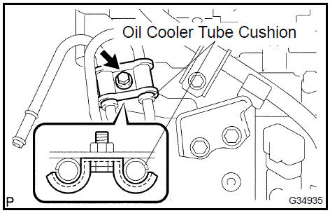
26. INSTALL OIL COOLER INLET TUBE No.1
- Temporarily install the oil cooler outlet tube No.1.
- Temporarily install the oil cooler inlet tube No.1.
- Install the oil cooler tube clamp with the bolt.
Torque: 5.4 N·m (55 kgf·cm, 48 in.·lbf)
HINT: Install them so that the oil cooler tube cushion is positioned as shown in the illustration.
- Torque the oil cooler inlet tube No.1.
Torque: 34 N·m (350 kgf·cm, 25 ft·lbf)
27. INSTALL OIL COOLER OUTLET TUBE No.1
- Torque the oil cooler outlet tube No.1.
Torque: 34 N·m (350 kgf·cm, 25 ft·lbf)
28. CONNECT CONNECTOR
- Connect the transmission wire connector.
- Connect the park/neutral position switch connector.
- Connect the 2 speed connectors.
- Connect the speedometer driven gear connector.
Install oil cooler outlet tube No.1
29. INSTALL STARTER ASSY
- Install the starter assy with the 2 bolts.
Torque: 37 N·m (377 kgf·cm, 27 ft·lbf)
- Connect the connecter.
- Connect the starter wire with the nut.
Torque: 9.8 N·m (100 kgf·cm, 87 in.·lbf)
Install starter assy
30. CONNECT WIRE HARNESS
- Connect the wire harness with the bolt.
Torque: 13 N·m (130 kgf·cm, 9 ft·lbf)

Connect wire harness
31. INSTALL WIRE HARNESS CLAMP
- Install the 2 clamps with the 2 bolts.
Torque: 8.4 N·m (86 kgf·cm, 74 in.·lbf)
- Connect the wire harnesses to the clamps
Install wire harness clamp
32. INSTALL TRANSMISSION CONTROL CABLE BRACKET No.2
- Install the transmission control cable bracket No.2 with
the bolt.
Torque: 12 N·m (122 kgf·cm, 9 ft·lbf)
 Install transmission control cable bracket No.2
- INSTALL FRONT DRIVE SHAFT ASSY LH
- INSTALL FRONT DRIVE SHAFT ASSY RH
- INSTALL ENGINE ASSEMBLY WITH TRANSAXLE
- RESET MEMORY
NOTICE: Perform the RESET MEMORY (AT initialization) when replacing the automatic transmission assy, engine assy or ECM .
HINT: RESET MEMORY can not be completed by only disconnecting the battery terminal.
Automatic transaxle assy (ATM)
Automatic transaxle assy (U250E)
Automatic transaxle fluid (ATM)
Torque converter clutch and drive plate (ATM)
Transmission revolution (ATM)
Park/neutral position switch assy (ATM)
Transmission wire (U151E)
Transmission wire (U250E)
Transmission valve body assy (U151E)
Transmission valve body assy (U151E)
Transmission valve body assy (U250E)
Front differential oil seal (U151E)
Front differential oil seal (U250E)
Shift lock system (ATM)
Floor shift assy (ATM)
Floor shift assy (ATM)
Transmission control cable assy (ATM)
Floor shift parking lock cable assy (ATM)
Park/neutral position switch assy (ATM)
Automatic transaxle assy (U151E)
Toyota Camry XV30 (2002–2006) Service Manual
- Introduction
- Audio & visual system
- Automatic transmission / trans
- Brake
- Clutch
- Communication system
- Cooling
- Cruise control
- Drive shaft / propeller shaft
- Emission control
- Engine control system
- Engine hood/door
- Engine mechanical
- Exhaust
- Exterior/interior trim
- Front suspension
- Fuel
- Heater & air conditioner
- Ignition
- Instrument panel/meter
- Intake
- Lighting
- Lubrication
- Manual transmission/transaxle
- Parking brake
- Power steering
- Rear suspension
- Seat
- Service specifications
- Sliding roof/convertible
- Starting & charging
- Steering column
- Supplemental restraint system
- Theft deterrent & door lock
- Tire & wheel
- Windshield/windowglass/mirror
- Wiper & washer
- Wiring
Categories
