 Toyota Camry XV30 (2002–2006) Service ManualAutomatic transmission / trans
Floor shift assy (ATM)
Floor shift assy (ATM)
COMPONENTS
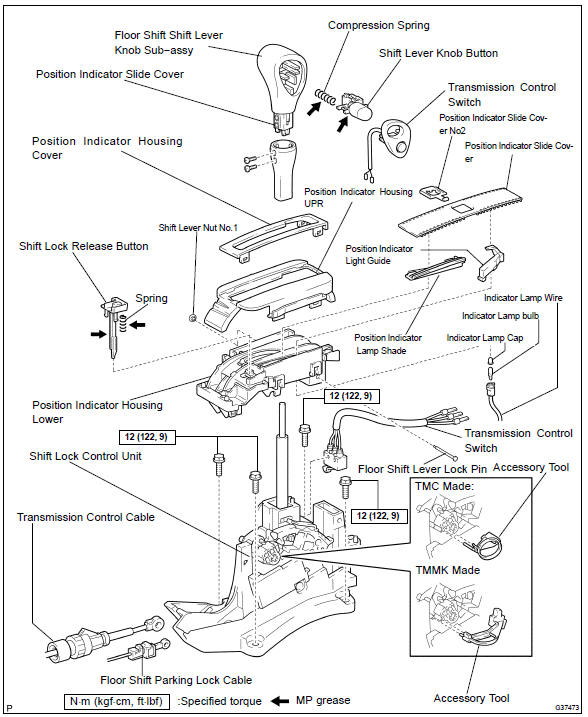
OVERHAUL
-
REMOVE CONSOLE BOX CARPET
-
REMOVE RR CONSOLE BOX
-
REMOVE FRONT ASH RECEPTACLE ASSY (W/ ASHTRAY)
-
REMOVE CONSOLE BOX FRONT
-
REMOVE AIR DUCT REAR No.1
-
REMOVE AIR DUCT REAR No.2
-
REMOVE CONSOLE BOX DUCT No.1
-
DISCONNECT FLOOR SHIFT PARKING LOCK CABLE ASSY
-
Disconnect the floor shift parking lock cable from the floor shift assy.
Disconnect floor shift parking lock cable assy
9. DISCONNECT TRANSMISSION CONTROL CABLE ASSY
-
Disconnect the floor shift cable transmission control shift from the floor shift assy.
10. REMOVE FLOOR SHIFT ASSY
-
Disconnect the shift lock control computer connector.
-
Disconnect the transmission control switch connector.
-
Remove the 4 bolts and transmission floor shift assy.
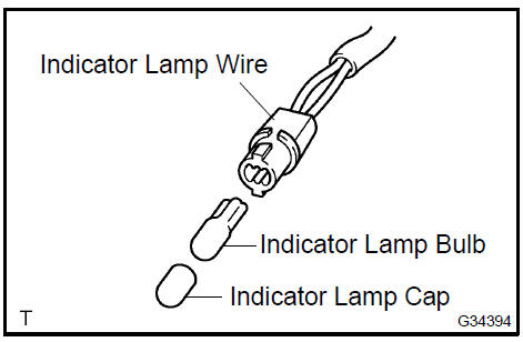
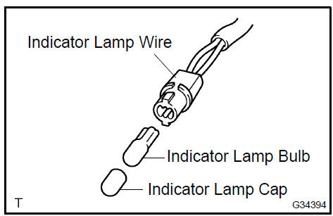
11. REMOVE INDICATOR LAMP WIRE SUB−ASSY
-
Releasing the lock by pressing the slick, disconnect the indicator lamp wire connector from the shift lever plate.
-
Disconnect the indicator lamp wire sub−assy from the position indicator housing.
-
Remove the indicator lamp cap and indicator lamp bulb from the indicator lamp wire sub−assy.
12. REMOVE SHIFT LEVER KNOB SUB−ASSY
-
Remove the 2 screws and shift lever knob from the shift lever.
-
Using a screwdriver, release the stopper of the connector.
-
Using a small screwdriver, disengage the locking lug of the terminals 3 and 7, and pull out the terminals from the rear.

13. REMOVE POSITION INDICATOR SLIDE COVER
-
Remove the position indicator slide cover from the floor shift assy.
 Remove position indicator slide cover
14. REMOVE TRANSMISSION CONTROL SWITCH
-
Using a screwdriver, remove the transmission control switch from the shift lever knob.
Remove transmission control switch
15. REMOVE SHIFT LEVER KNOB BUTTON
-
Using a screwdriver, release the claw and remove the shift lever knob button.
-
Remove the compression spring.
Remove shift lever knob button
16. REMOVE POSITION INDICATOR HOUSING UPPER
-
Using a screwdriver, disengage the 4 claws and remove the position indicator housing upper from the floor shift assy.
Remove position indicator housing upper
17. REMOVE POSITION INDICATOR HOUSING COVER
-
Using a screwdriver, remove the position indicator housing cover from the position indicator housing upper.
Remove position indicator housing cover
18. REMOVE POSITION INDICATOR SLIDE COVER
-
Remove the position indicator slide cover from the floor shift assy.
-
Remove the position indicator slide cover No.2 from the floor shift assy.
19. REMOVE SHIFT LOCK RELEASE BUTTON
-
While pressing the 2 claws, remove the shift lock release button and shift lock release spring.
Remove position indicator slide cover
20. REMOVE POSITION INDICATOR LIGHT GUIDE
-
Disengage the 2 claws and remove the position indicator lamp shade from the position indicator housing lower.
-
Remove the position indicator light guide from the position indicator housing lower.

21. REMOVE POSITION INDICATOR HOUSING LOWER
-
Using a screwdriver, pry up the shift lever nut No.1.
-
Using a screwdriver, pry up the floor shift lever lock pin.
-
Using a screwdriver release the 2 claws and remove the position indicator housing lower from the floor shift assy.
Remove position indicator housing lower
18. REMOVE POSITION INDICATOR SLIDE COVER
-
Remove the position indicator slide cover from the floor shift assy.
-
Remove the position indicator slide cover No.2 from the floor shift assy.
19. REMOVE SHIFT LOCK RELEASE BUTTON
-
While pressing the 2 claws, remove the shift lock release button and shift lock release spring.
Remove shift lock release button
20. REMOVE POSITION INDICATOR LIGHT GUIDE
-
Disengage the 2 claws and remove the position indicator lamp shade from the position indicator housing lower.
-
remove the position indicator light guide from the position indicator housing lower.
21. REMOVE POSITION INDICATOR HOUSING LOWER
-
Using a screwdriver, pry up the shift lever nut No.1.
-
Using a screwdriver, pry up the floor shift lever lock pin.
-
Using a screwdriver release the 2 claws and remove the position indicator housing lower from the floor shift assy.
Remove position indicator housing lower
22. REMOVE TRANSMISSION CONTROL SWITCH
-
Using a screwdriver, remove the transmission control switch from the floor shift assy.
-
Using a screwdriver, release the stopper of the connector.
-
Using a small screwdriver, disengage the locking lug of the terminals 1 , 2 and 6 and pull the terminals out from the rear.
23. INSTALL TRANSMISSION CONTROL SWITCH
-
Install the 3 terminals into the indicator lamp wire connector.
-
Install the transmission control switch to the floor shift assy.
24. INSTALL POSITION INDICATOR HOUSING LOWER
-
Install the position indicator housing lower with the shift lever lock pin and a new shift lever nut No.1.
HINT: Ensure that the claws fit tightly
Install position indicator housing lower
25. INSTALL POSITION INDICATOR LIGHT GUIDE
-
Install the position indicator light guide to the position indicator housing lower.
-
Install the position indicator lamp shade to the position indicator housing lower.
26. INSTALL SHIFT LOCK RELEASE BUTTON
-
Apply MP grease to the shift lock release spring and shift lock release button.
-
Install the shift lock release button and shift lock release spring to the position indicator housing lower.
HINT: Ensure that the claws fit tightly.
 Install shift lock release button
27. INSTALL POSITION INDICATOR SLIDE COVER
-
Install the position indicator slide cover No.2 to the position indicator.
-
Install the position indicator slide cover to the floor shift assy.
28. INSTALL POSITION INDICATOR HOUSING COVER
-
Install the position indicator housing cover to the position indicator housing upper.
HINT: Ensure that the claws fit tightly.
Install position indicator housing cover
29. INSTALL POSITION INDICATOR HOUSING UPPER
-
Install the control position indicator housing upper.
HINT: Ensure that the claws fit tightly.
Install position indicator housing upper
30. INSTALL SHIFT LEVER KNOB BUTTON
-
Apply MP grease to the shift lever knob button and compression spring and install them to the shift lever knob.
HINT: Ensure that the claws fit tightly.
Install shift lever knob button
31. INSTALL TRANSMISSION CONTROL SWITCH
-
Install the transmission control switch to the shift lever knob.
HINT: Ensure that the claws fit tightly.
32. INSTALL POSITION INDICATOR SLIDE COVER
-
Install the position indicator slide cover to the floor shift assy.
Install position indicator slide cover
33. INSTALL SHIFT LEVER KNOB SUB−ASSY
-
Install the 2 terminals into the indicator lamp wire connector.
-
Install the shift lever knob to the shift lever with 2 screws.
34. INSTALL INDICATOR LAMP WIRE SUB−ASSY
-
Install the indicator lamp bulb and indicator lamp cap to the indicator lamp wire.
-
Install the indicator lamp wire to the position indicator housing lower.
-
Install the indicator lamp wire harness and connector as shown in the illustration.
35. INSTALL FLOOR SHIFT ASSY
-
Install the floor shift assy to the vehicle with the 4 bolts.
Torque: 12 N·m (122 kgf·cm, 9 ft·lbf)
HINT: Tighten them in the order, A, B, C and D
-
Connect the transmission control switch connector.
-
Connect the shift lock control computer connector.
Install floor shift assy
36. CONNECT TRANSMISSION CONTROL CABLE ASSY
-
Connect the floor shift cable to the floor shift assy.
HINT: Install it with the uneven surface f
Connect transmission control cable assy
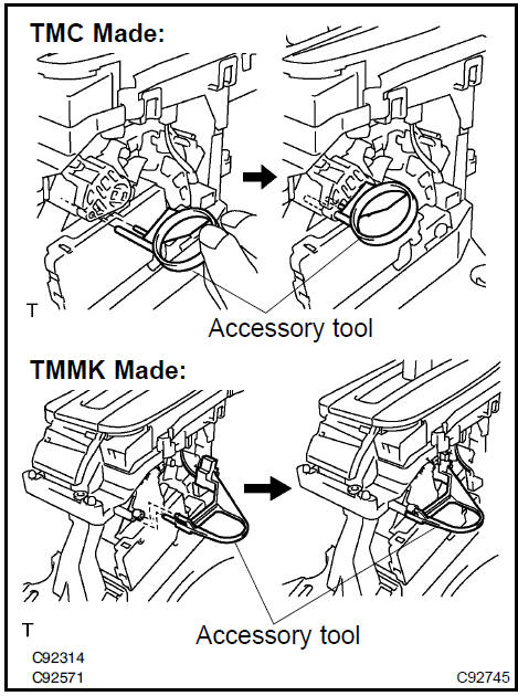
37. CONNECT FLOOR SHIFT PARKING LOCK CABLE ASSY
-
Set the accessory tool.
-
Shift the shift lever to P position and turn the ignition switch to the LOCK position. (TMC made)
-
Shift the shift lever to N position and turn the ignition switch to the ACC. position (TMMK made)
-
Set the accessory tool to the shift lock control unit assy as shown in the illustration.
Accessory tool parts No.: TMC Made: 33693−33010 TMMK Made: 33693−06010
HINT: Only in the case of reusing the shift lock control unit assy.
-
Using a screwdriver, unlock the claw of the lock key of automatic adjustment part.
-
Insert the lever pin into the hole in the floor shift parking lock cable.
HINT: Ensure that the claws fit tightly.
-
Lock the lock key.
HINT:
-
At this time, the shift lever should be in P position and the ignition key should be set to LOCK position. (TMC Made)
-
At this time, the shift lever should be in N position and the ignition key should be set to ACC position. (TMMK Made)
-
Remove the accessory tool.
Accessory tool parts No.: TMC Made: 33693−33010 TMMK Made: 33693−06010
-
CHECK KEY INTERLOCK OPERATION
-
CHECK SHIFT LOCK OPERATION
-
CHECK SHIFT LOCK RELEASE BUTTON OPERATION
-
INSTALL CONSOLE BOX DUCT No.1
-
INSTALL AIR DUCT REAR No.2
-
INSTALL AIR DUCT REAR No.1
-
INSTALL CONSOLE BOX FRONT
-
INSTALL FRONT ASH RECEPTACLE ASSY (W/ ASHTRAY)
-
INSTALL RR CONSOLE BOX
-
INSTALL CONSOLE BOX CARPET
Automatic transaxle assy (ATM)
Automatic transaxle assy (U250E)
Automatic transaxle fluid (ATM)
Torque converter clutch and drive plate (ATM)
Transmission revolution (ATM)
Park/neutral position switch assy (ATM)
Transmission wire (U151E)
Transmission wire (U250E)
Transmission valve body assy (U151E)
Transmission valve body assy (U151E)
Transmission valve body assy (U250E)
Front differential oil seal (U151E)
Front differential oil seal (U250E)
Shift lock system (ATM)
Floor shift assy (ATM)
Floor shift assy (ATM)
Transmission control cable assy (ATM)
Floor shift parking lock cable assy (ATM)
Park/neutral position switch assy (ATM)
Automatic transaxle assy (U151E)
Toyota Camry XV30 (2002–2006) Service Manual
- Introduction
- Audio & visual system
- Automatic transmission / trans
- Brake
- Clutch
- Communication system
- Cooling
- Cruise control
- Drive shaft / propeller shaft
- Emission control
- Engine control system
- Engine hood/door
- Engine mechanical
- Exhaust
- Exterior/interior trim
- Front suspension
- Fuel
- Heater & air conditioner
- Ignition
- Instrument panel/meter
- Intake
- Lighting
- Lubrication
- Manual transmission/transaxle
- Parking brake
- Power steering
- Rear suspension
- Seat
- Service specifications
- Sliding roof/convertible
- Starting & charging
- Steering column
- Supplemental restraint system
- Theft deterrent & door lock
- Tire & wheel
- Windshield/windowglass/mirror
- Wiper & washer
- Wiring
Categories
