 Toyota Camry XV30 (2002–2006) Service ManualBrake
Front brake
Front brake
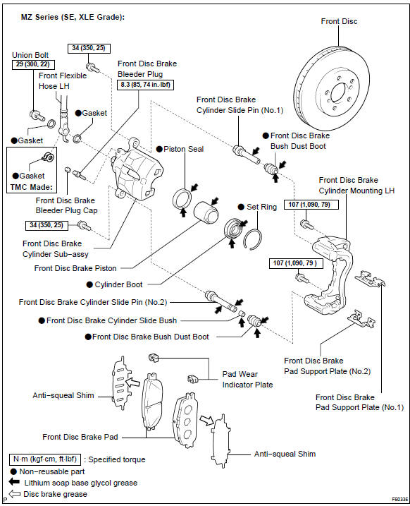
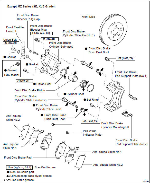
COMPONENTS
OVERHAUL
HINT:
-
Use the same procedures for the RH side and LH side.
-
The procedures listed below are for the LH side.
-
REMOVE FRONT WHEEL
-
DRAIN BRAKE FLUID
NOTICE: Wash brake fluid off immediately if it adheres to any painted surface.
3. DISCONNECT FRONT FLEXIBLE HOSE
-
Remove the union bolt and the gaskets. from the disc brake cylinder sub−assy, then disconnect the flexible hose.
HINT: Gasket has 2 types: 2−piece type and 1−piece type.
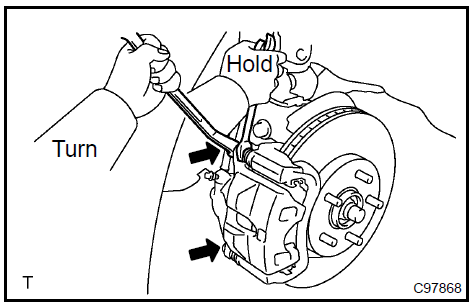
4. REMOVE FRONT DISC BRAKE CYLINDER SUB−ASSY
-
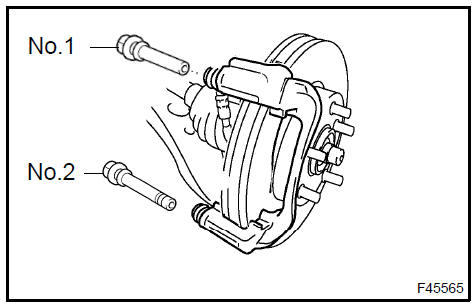
Hold the front disc brake cylinder slide pin (No.1) and slide pin (No.2), and remove the 2 bolts.
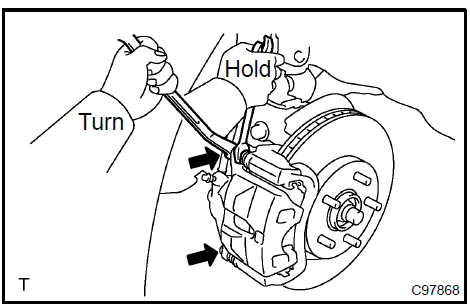 Remove front disc brake cylinder sub-assy
5. REMOVE DISC BRAKE PAD KIT FRONT (PAD ONLY)
-
Remove the 2 disc brake pads with anti−squeal shims from the front disc brake cylinder mounting LH.
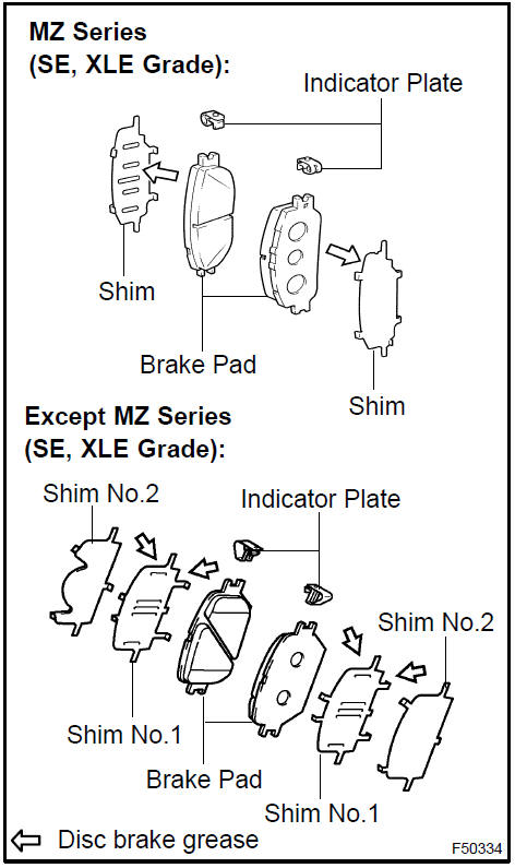
6. REMOVE ANTI SQUEAL SHIM KIT FRONT
-
MZ Series (SE, XLE Grade): Remove the 2 anti−squeal shims from each pad.
-
Except MZ Series (SE, XLE Grade): Remove the 4 anti−squeal shims from each pad.
-
Using a screwdriver, remove the pad wear indicator plates from each pad.
 Remove anti squeal shim kit front
7. REMOVE FRONT DISC BRAKE PAD SUPPORT PLATE
-
Remove the front disc brake pad support plate (No.1) and front disc brake pad support plate (No.2) from the front disc brake cylinder mounting LH.
8. REMOVE FRONT DISC BRAKE CYLINDER SLIDE PIN
-
Remove the front disc brake cylinder slide pin (No.1) and front disc brake cylinder slide pin (No.2) from the front disc brake cylinder mounting LH.
 Remove front disc brake cylinder slide pin
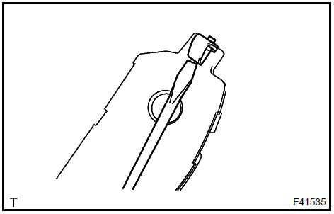
9. REMOVE FRONT DISC BRAKE CYLINDER SLIDE BUSH
-
Using a screwdriver, remove the front disc brake cylinder slide bush from the front disc brake cylinder slide pin (No.2).
NOTICE: Do not damage the front disc brake cylinder slide pin (No.2).
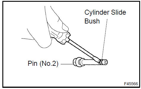 Remove front disc brake cylinder slide bush
10. REMOVE FRONT DISC BRAKE CYLINDER MOUNTING
-
Remove the 2 bolts and front disc brake cylinder mounting LH.
Remove front disc brake cylinder mounting
11. REMOVE FRONT DISC BRAKE BUSH DUST BOOT
-
Hold the front disc brake cylinder mounting LH in the vise through the soft jaws.
-
Using a screwdriver and a hammer, remove the 2 front disc brake bush dust boots from the front disc brake cylinder mounting LH
Remove front disc brake bush dust boot
12. REMOVE CYLINDER BOOT
-
Using a screwdriver, remove the set ring and cylinder boot.
NOTICE: Do not damage the piston groove and cylinder groove.
Remove cylinder boot
13. REMOVE FRONT DISC BRAKE PISTON
-
Place a shop rag between the front disc brake piston and the disc brake cylinder sub−assy.
-
Use compressed air to remove the front disc brake piston from the disc brake cylinder sub−assy.
CAUTION: Do not place your fingers in front of the piston when using compressed air.
NOTICE: Do not spatter the brake fluid.
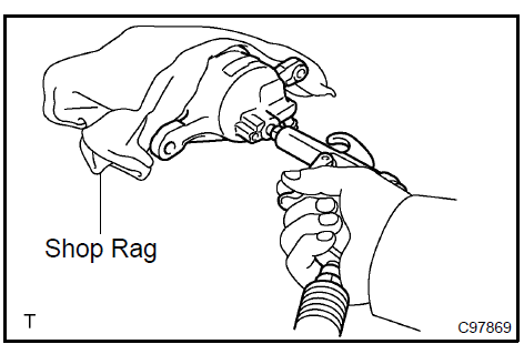
Remove front disc brake piston
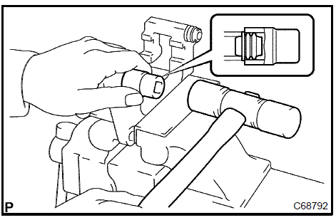
14. REMOVE PISTON SEAL
-
Using a screwdriver, remove the piston seal from the front disc brake cylinder sub−assy.
NOTICE: Do not damage the inner cylinder and cylinder groove.
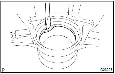
Remove piston seal
-
REMOVE FRONT DISC BRAKE BLEEDER PLUG CAP
-
REMOVE FRONT DISC BRAKE BLEEDER PLUG
-
INSPECT BRAKE CYLINDER AND PISTON
-
Check the brake cylinder bore and front disc brake piston for rust or scoring.
If necessary, replace the brake cylinder and piston.
18. INSPECT PAD LINING THICKNESS
-
Using a ruler, measure the pad lining thickness.
Standard thickness: 12.0 mm (0.472 in.) Minimum thickness: 1.0 mm (0.039 in.)
If the pad lining thickness is equal to the minimum thickness or less, replace the brake pad.
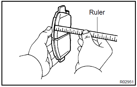
Inspect pad lining thickness
19. INSPECT FRONT DISC BRAKE PAD SUPPORT PLATE
-
Inspect the front disc brake pad support plate (No.1) and front disc brake pad support plate (No.2).
HINT: Make sure that both have sufficient rebound, have no deformation, cracks or wear, and that all rust and dirt is cleaned off.
If necessary, replace the brake pad support plate.
20. INSPECT DISC THICKNESS
-
Using a micrometer, measure the disc thickness.
Standard thickness: 28.0 mm (1.102 in.) Minimum thickness: 26.0 mm (1.024 in.)
If the disc thickness is less than the minimum, replace the disc.
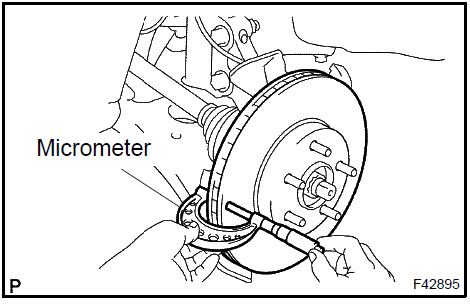
Inspect disc thickness
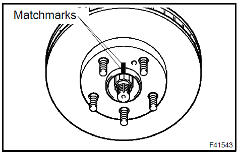
21. REMOVE FRONT DISC
-
Put matchmarks on the front disc and the axle hub.
-
Remove the front disc.
22. INSTALL FRONT DISC
-
Aligning the matchmarks, install the front disc.
HINT: When replacing the disc with a new one, select the installation position where the front disc has the minimum runout.
Install front disc
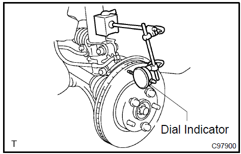
23. INSPECT DISC RUNOUT
-
Check the bearing play in the axial direction and check for the axle hub runout .
-
Temporarily fasten the front disc together with the hub nuts.
Torque: 103 N·m (1,050 kgf·cm, 76 ft·lbf)
-
Using a dial indicator, measure the disc runout 10 mm (0.39 in.) away from the outer edge of the front disc.
Maximum disc runout: 0.05 mm (0.0020 in.)
If the runout exceeds the maximum value, change the installation positions of the disc and axle so that the runout will become minimal. If the runout exceeds the maximum even when the installation positions are changed, grind the disc. If the disc thickness is less than the minimum, replace the front disc.
Inspect disc runout
-
TEMPORARILY TIGHTEN FRONT DISC BRAKE BLEEDER PLUG
-
INSTALL FRONT DISC BRAKE BLEEDER PLUG CAP
-
INSTALL PISTON SEAL
-
Apply lithium soap base glycol grease to a new piston seal.
-
Install the piston seal to the front disc brake cylinder sub−assy.
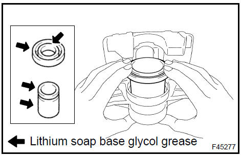
27. INSTALL FRONT DISC BRAKE PISTON
-
Apply lithium soap base glycol grease to the front disc brake piston and new cylinder boot.
-
Install the cylinder boot to the front disc brake piston.
-
Install the front disc brake piston to the front disc brake cylinder sub−assy.
NOTICE: Do not install the piston forcibly in the front disc brake cylinder sub−assy.
 Install front disc brake piston
28. INSTALL CYLINDER BOOT
-
Install the cylinder boot to the front disc brake cylinder sub−assy.
NOTICE: Install the boot securely to the grooves of the cylinder and piston.
-
Using a screwdriver, install the set ring.
NOTICE: Do not damage the cylinder boot.
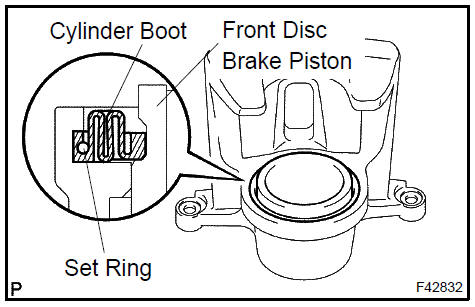
Install cylinder boot
29. INSTALL FRONT DISC BRAKE BUSH DUST BOOT
-
Hold the front disc brake cylinder mounting LH in the vise through the soft jaws.
-
Place the front disc brake cylinder mounting LH in the vise.
-
Apply lithium soap base glycol grease to the sealing surface of 2 new front disc brake bush dust boots.
-
Using a socket wrench (19 mm) and a hammer, drive the 2 front disc brake bush dust boots to the front disc brake cylinder mounting LH.
Install front disc brake bush dust boot
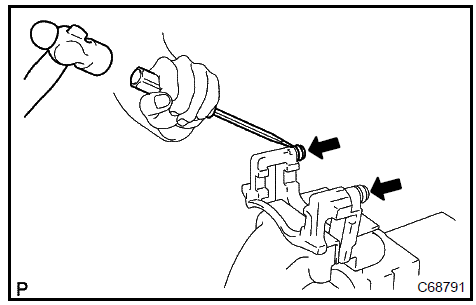
30. INSTALL FRONT DISC BRAKE CYLINDER SLIDE BUSH
-
Apply lithium soap base glycol grease to a new front disc brake cylinder slide bush.
-
Install the cylinder slide bush to the bottom side of the front disc brake cylinder slide pin (No.2).
31. INSTALL FRONT DISC BRAKE CYLINDER MOUNTING
-
Install the front disc brake cylinder mounting with the 2 bolts.
Torque: 107 N·m (1,090 kgf·cm, 79 ft·lbf)
 Install front disc brake cylinder mounting
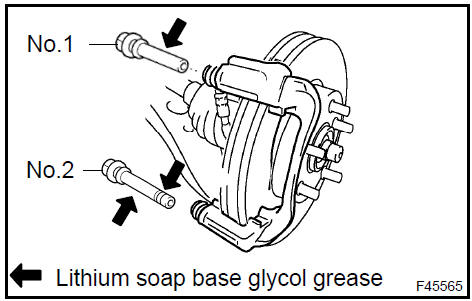
32. INSTALL FRONT DISC BRAKE CYLINDER SLIDE PIN
-
Apply lithium soap base glycol grease to the sliding part and the sealing surface of the front disc brake cylinder slide pin (No.1) and front disc brake cylinder slide pin (No.2).
-
Install the front disc brake cylinder slide pin (No.1) and front disc brake cylinder slide pin (No.2) to the front disc brake cylinder mounting LH.
Install front disc brake cylinder slide pin
33. INSTALL FRONT DISC BRAKE PAD SUPPORT PLATE
-
Install the front disc brake pad support plate (No.1) and front disc brake pad support plate (No.2) to the front disc brake cylinder mounting LH.
NOTICE: Install the pad support plates in the correct position and direction.
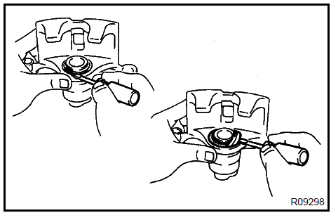
34. INSTALL ANTI SQUEAL SHIM KIT FRONT
NOTICE:
-
When replacing worn pads, the anti−squeal shims must be replaced together with the pads.
-
Install the shims and pad wear indicator plates in the correct position and direction.
-
Apply disc brake grease to the anti−squeal shims as shown in the illustration.
-
Install the anti−squeal shims on each pad as shown in the illustration.
-
Install the pad wear indicator plates to each pad.
Install anti squeal shim kit front
35. INSTALL DISC BRAKE PAD KIT FRONT (PAD ONLY)
-
Install the disc brake pad kit front to the front disc brake cylinder mounting LH.
NOTICE:
-
There should be no oil or grease on the friction surface of the pads and the disc.
-
Brake pads are installed with indicator plates facing upward.
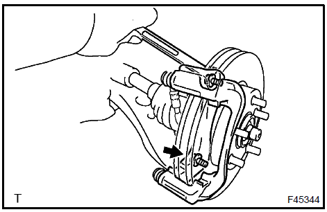
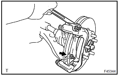
36. INSTALL FRONT DISC BRAKE CYLINDER SUB−ASSY
-
Install the front disc brake cylinder sub−assy with the 2 bolts.
Torque: 34 N·m (350 kgf·cm, 25 ft·lbf)
Install front disc brake cylinder sub-assy
37. INSTALL FRONT FLEXIBLE HOSE
-
Install new gaskets. and flexible hose with the union bolt.
Torque: 29 N·m (300 kgf·cm, 22 ft·lbf)
NOTICE: Install the flexible hose lock securely in the lock hole in the disc brake cylinder.
HINT: Gasket has 2 types: 2−piece type and 1−piece type.
-
FILL RESERVOIR WITH BRAKE FLUID
-
BLEED MASTER CYLINDER
SST 09023−00101
-
BLEED BRAKE LINE
-
CHECK FLUID LEVEL IN RESERVOIR
-
CHECK FOR BRAKE FLUID LEAKAGE
-
INSTALL FRONT WHEEL Torque: 103 N·m (1,050 kgf·cm, 76 ft·lbf)
Brake system
Brake pedal support assy
Accelerator & brake pedal assy
Brake system
Brake master cylinder sub-assy
Brake booster assy
Front brake
Brake fluid
Rear disc brake
Rear drum brake
Brake actuator assy (W/O VSC)
Brake actuator assy (W/ VSC)
Speed front LH
Skid control
Yawrate
Steering
Adjustable pedal switch
Adjustable pedal relay
Brake pedal support assy
Toyota Camry XV30 (2002–2006) Service Manual
- Introduction
- Audio & visual system
- Automatic transmission / trans
- Brake
- Clutch
- Communication system
- Cooling
- Cruise control
- Drive shaft / propeller shaft
- Emission control
- Engine control system
- Engine hood/door
- Engine mechanical
- Exhaust
- Exterior/interior trim
- Front suspension
- Fuel
- Heater & air conditioner
- Ignition
- Instrument panel/meter
- Intake
- Lighting
- Lubrication
- Manual transmission/transaxle
- Parking brake
- Power steering
- Rear suspension
- Seat
- Service specifications
- Sliding roof/convertible
- Starting & charging
- Steering column
- Supplemental restraint system
- Theft deterrent & door lock
- Tire & wheel
- Windshield/windowglass/mirror
- Wiper & washer
- Wiring
Categories
