 Toyota Camry XV30 (2002–2006) Service ManualManual transmission/transaxle
Manual transaxle assy (E351)
Manual transaxle assy (E351)
OVERHAUL
1. REMOVE CLUTCH RELEASE FORK SUB−ASSY
a. Remove the clutch release fork with clutch release bearing from the manual transaxle case.
 Remove clutch release fork sub-assy
2. REMOVE CLUTCH RELEASE BEARING ASSY
a. Remove the clutch release bearing assy and clutch release bearing hub clip from the clutch release fork sub−assy.
3. REMOVE RELEASE FORK SUPPORT
a. Remove the release fork support from the manual transaxle case.
 Remove release fork support
4. REMOVE CLUTCH RELEASE FORK BOOT
a. Remove the clutch release fork boot from the manual transaxle case.
5. REMOVE SPEEDOMETER DRIVEN HOLE COVER SUB−ASSY
a. Remove the bolt and speedometer driven hole cover.
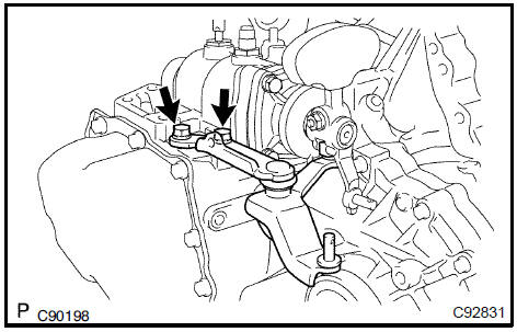
6. REMOVE SELECTING BELL CRANK ASSY
a. Remove the 2 bolts and selecting bell crank assy from manual transmission case.
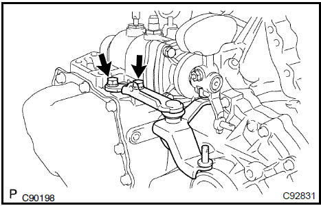 Remove selecting bell crank assy
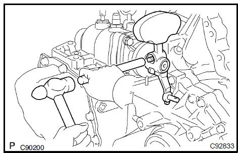
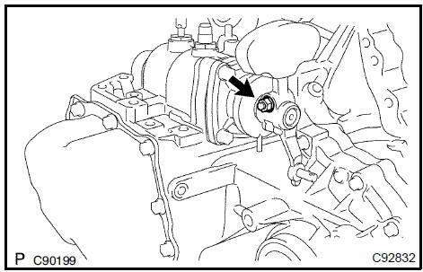
7. REMOVE CONTROL SHIFT LEVER
a. Remove the nut and spring washer.
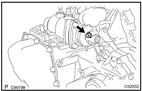
- Using a brass bar and hammer, remove the shift outer lock pin.
- Remove the control shift lever.
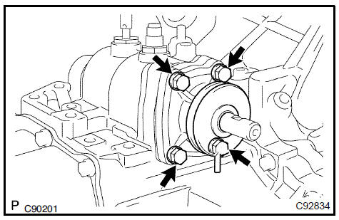
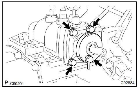
8. REMOVE CONTROL SHAFT COVER
a. Remove the 4 bolts and control shaft cover from the manual transmission case.
 Remove control shaft cover
9. FIX MANUAL TRANSAXLE ASSY
a. Using wooden blocks, fix the manual transaxle assy.
 Fix manual transaxle assy
10. REMOVE LOCK BALL ASSY No.1
a. Remove the lock ball assy No.1 from the manual transmission case.
 Remove lock ball assy No.1
11. REMOVE MANUAL TRANSMISSION BREATHER PLUG
a. Remove the manual transmission breather plug and gasket.
 Remove manual transmission breather plug
12. REMOVE SHIFT & SELECT LEVER SHAFT ASSY
a. Remove the shift & select lever shaft assy from the manual transmission case.
 Remove shift & select lever shaft assy
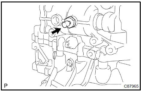
13. REMOVE BACK UP LAMP SWITCH ASSY
a. Remove the back up lamp switch assy and gasket from the manual transmission case.
 Remove back up lamp switch assy
14. REMOVE MANUAL TRANSMISSION FILLER PLUG
a. Remove the manual transmission filler plug and gasket from the manual transmission case.
 Remove manual transmission filler plug
15. REMOVE DRAIN (MTM) PLUG SUB−ASSY
a. Remove the drain (MTM) plug sub−assy and gasket from the manual transmission case.
 Remove drain (MTM) plug sub-assy
16. REMOVE MANUAL TRANSMISSION CASE COVER SUB−ASSY
a. Remove the 10 bolts and manual transmission case cover from the manual transmission case.
 Remove manual transmission case cover sub-assy
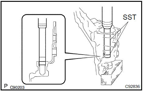
17. REMOVE MANUAL TRANSMISSION OUTPUT SHAFT REAR SET NUT
a. Engage the gear to the double meshing.
b. Using SST and a hammer, loosen the staked part of the manual transmission output shaft rear set nut.
SST 09930−00010
- Using SST, remove the manual transmission output shaft
rear set nut from the output shaft.
SST 09229−55010
- Disengage the double meshing of the gear.
18. INSPECT 5TH GEAR THRUST CLEARANCE
a. Using a dial indicator, inspect the 5th gear thrust clearance.
Standard clearance: 0.10 to 0.65 mm (0.0039 to 0.0256 in.)
 Inspect 5th gear thrust clearance
19. INSPECT 5TH GEAR RADIAL CLEARANCE
a. Using a dial indicator, inspect the 5th gear radial clearance.
Standard clearance: 0.009 to 0.050 mm (0.0004 to 0.0020 in.)
HINT: If the clearance is out of the specification, replace 1st gear needle roller bearing.
 Inspect 5th gear radial clearance
20. REMOVE TRANSMISSION CLUTCH HUB No.3
a. Using 2 screwdrivers and hammer, remove the transmission clutch hub No.3 shaft snap ring from the input shaft.
HINT: Using a waste to prevent the snap ring from being scattered.
b. Remove the gear shift fork bolt from the gear shift fork No.3.
c. Using SST, remove the transmission clutch hub No.3 and gear shift fork No.3 from the input shaft.
SST 09950−30012 (09951−03010, 09953−03010, 09954−03010), 09950−50013 (09957−04010), 09950−60010 (09951−00280)
21. REMOVE 5TH GEAR
a. Remove the 5th gear from the input shaft.
 Remove 5th gear
22. REMOVE 5TH GEAR NEEDLE ROLLER BEARING
a. Remove the 5th gear needle roller bearing from the input Shaft.
 Remove 5th gear needle roller bearing
23. REMOVE 5TH DRIVEN GEAR
a. Using SST, remove the 5th driven gear from the output shaft.
SST 09950−30012 (09951−03010, 09953−03010, 09954−03010, 09957−04010), 09950−60010 (09951−00180, 09955−03011), 09950−50013
 Remove 5th driven gear
24. REMOVE BEARING RETAINER REAR (MTM)
a. Using a torx socket wrench (T45), remove the 7 torx screws and bearing retainer rear (MTM) from the manual transmission case.
 Remove bearing retainer rear (MTM)
25. REMOVE OUTPUT SHAFT REAR BEARING SHIM
a. Remove the output shaft rear bearing shim from the output shaft.
 Remove output shaft rear bearing shim
26. REMOVE INPUT SHAFT REAR BEARING SHAFT SNAP RING
a. Using a snap ring expander, remove the input shaft rear bearing shaft snap ring from the input shaft.
 Remove input shaft rear bearing shaft snap ring
27. REMOVE SHIFT FORK SHAFT SHAFT SNAP RING
a. Using 2 screwdrivers and a hammer, remove the shift fork shaft shaft snap ring from the gear shift fork shaft No.1.
HINT: Using a waste to prevent the snap ring from being scattered.
b. Using 2 screw drivers and a hammer, remove the shift fork shaft shaft snap ring from the gear shift fork shaft No.2.
HINT: Using a waste to prevent the snap ring from being scattered.
28. REMOVE REVERSE IDLER GEAR SHAFT BOLT
a. Remove the reverse idler gear shaft bolt and gasket.
 Remove reverse idler gear shaft bolt
29. REMOVE CLUTCH TUBE BRACKET No.1
a. Remove the 3 bolts and remove the clutch tube bracket.
30. REMOVE MANUAL TRANSMISSION CASE
a. Remove the 3 bolts of the manual transaxle case side.
- Remove the 14 bolts of the manual transmission case side.
- Using a plastic hammer, remove the manual transmission case.
31. REMOVE OIL RECEIVER PIPE No.2 (MTM)
a. Remove the bolt and oil receiver pipe No.2 (MTM) from the manual transmission case.
NOTICE: Do not damage the pipe.
 Remove oil receiver pipe No.2 (MTM)
32. REMOVE OIL RECEIVER PIPE No.1 (MTM)
a. Remove the bolt and oil receiver pipe No.1 (MTM) from the manual transmission case.
NOTICE: Do not damage the pipe.
 Remove oil receiver pipe No.1 (MTM)
33. REMOVE REVERSE RESTRICT PIN ASSY
a. Using a hexagon wrench (6 mm), remove the reverse restrict pin plug from the manual transmission case.
b. Using a pin punch (ϕ 5 mm), remove the slotted pin and reverse restrict pin assy.
34. REMOVE TRANSMISSION MAGNET
a. Remove the transmission magnet from the manual transaxle case.
 Remove transmission magnet
35. REMOVE REVERSE IDLER GEAR SUB−ASSY
a. Remove the reverse idler gear sub−assy from the manual transaxle case.
b. Remove the reverse gear and reverse idler thrust washer from the reverse idler gear shaft.
36. REMOVE REVERSE SHIFT ARM BRACKET ASSY
a. Remove the 2 bolts and reverse shift arm bracket from the manual transaxle case.
 Remove reverse shift arm bracket assy
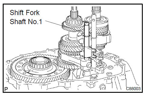
37. REMOVE GEAR SHIFT FORK SHAFT No.1
a. Remove the shift fork bolt from the gear shift fork No.1.
b. Pull out the gear shift fork shaft No.1 Ωhile the gear fork shaft No.3 is pulled up.
c. Using 2 screwdrivers and a hammer, remove the shift fork shaft snap ring from the gear shift fork shaft No.1.
NOTICE: Using a waste to prevent the snap ring from being sc
attered.
38. REMOVE REVERSE SHIFT FORK ROLLER
a. Using a magnetic finger, remove the reverse shift fork roller from the reverse shift fork.
 Remove reverse shift fork roller
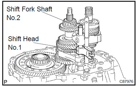
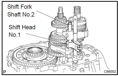
39. REMOVE GEAR SHIFT FORK SHAFT No.2
a. Remove the 2 shift fork bolts from the gear shift fork No.2 and gear shift head No.1.
b. Remove the gear shift fork shaft No.2 and gear shift head No.1 from the manual transaxle case.
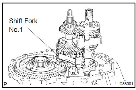
40. REMOVE GEAR SHIFT FORK No.1
 Remove gear shift fork No.1
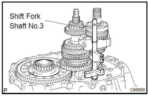
41. REMOVE GEAR SHIFT FORK SHAFT No.3
a. Remove the gear shift fork shaft No.3 from the manual transaxle case.
- Using 2 screwdrivers and a hammer, remove the 2 shift fork shaft snap rings from the gear shift fork shaft No. 3.
- Remove the reverse shift fork from the gear shift fork shaft No.3.
42. REMOVE GEAR SHIFT FORK No.2
a. Remove the gear shift fork No.2 from the input shaft assy.
 Remove gear shift fork No.2
43. REMOVE INPUT SHAFT ASSY
a. Incline the output shaft then remove the input shaft from the manual transaxle case.
 Remove input shaft assy
44. REMOVE OUTPUT SHAFT ASSY
a. Remove the output shaft from the manual transaxle case.
 Remove output shaft assy
45. REMOVE DIFFERENTIAL CASE ASSY
a. Remove the differential case assy from the manual transaxle case.
 Remove differential case assy
46. REMOVE MANUAL TRANSAXLE CASE RECEIVER
a. Remove the 3 bolts and manual transaxle case receiver from the manual transaxle case.
 Remove manual transaxle case receiver
47. REMOVE INPUT SHAFT FRONT BEARING
a. Using SST, remove the input shaft front bearing (outer race) from the manual transaxle case.
SST 09612−65014 (09612−01040, 09612−01050)
 Remove input shaft front bearing
48. REMOVE FRONT TRANSAXLE CASE OIL SEAL
a. Using SST, remove the manual transaxle case oil seal from the manual transaxle case.
SST 09612−65014 (09612−01040, 09612−01050)
 Remove front transaxle case oil seal
49. REMOVE OUTPUT SHAFT FRONT BEARING
a. Using SST, remove the output shaft front bearing (outer race) from the manual transaxle case.
SST 09387−00041 (09387−02020, 09387−02010)
 Remove output shaft front bearing
50. REMOVE OUTPUT SHAFT (MTM) COVER
a. Remove the output shaft (MTM) cover from the manual transaxle case.
 Remove output shaft (MTM) cover
51. REMOVE OUTPUT SHAFT REAR BEARING
a. Using SST, remove the output shaft rear bearing from the manual transmission case (outer race).
SST 09950−60010 (09951−00680), 09950−70010 (09951−07100)
 Remove output shaft rear bearing
52. REMOVE TRANSMISSION CASE OIL SEAL
a. Using SST, remove the transmission case oil seal from the manual transmission case.
SST 09308−00010
 Remove transmission case oil seal
53. REMOVE FRONT TRANSAXLE CASE COVER OIL SEAL
a. Using a screwdriver, remove the front transaxle case cover oil seal.
HINT: Tape the screwdriver tip before use.
 Remove front transaxle case cover oil seal
54. REMOVE FR DIFFERENTIAL CASE REAR TAPERED ROLLER BEARING
a. Using a brass bar and a hammer, remove the FR differential case rear tapered roller bearing (outer race) from the manual transaxle case.
b. Using SST, remove the front differential case rear tapered roller bearing from the front differential case.
SST 09950−00020, 09950−00030, 09950−40011 (09957−04010), 09950−60010 (09951−00560)
55. REMOVE FR DIFFERENTIAL CASE FRONT TAPERED ROLLER BEARING
a. Using SST and hammer, remove the FR differential case front tapered roller bearing (outer race) and FR differential case rear shim from the manual transmission case.
SST 09950−60020 (09951−00790), 09950−70010 (09951−07100)
b. Using SST, remove the FR differential case front tapered roller bearing (inner race) from front differential case.
SST 09950−00020, 09950−00030, 09950−40011 (09957−04010), 09950−60010 (09951−00490)
56. REMOVE CONTROL SHAFT COVER BIMETAL FORMED BUSH
a. Using SST, remove the shift & select lever shaft bimetal formed bush.
SST 09319−60020
 Remove control shaft cover bimetal formed bush
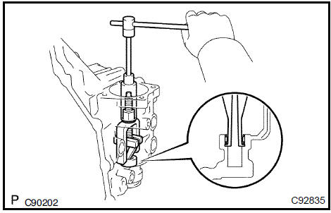
57. INSPECT REVERSE IDLER GEAR SUB−ASSY
a. Using a callipers gauge, measure the inside diameter of the reverse idler gear.
Inside diameter: mm (in.)
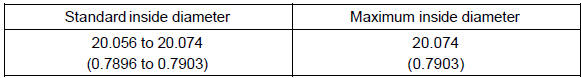
If the inside diameter exceeds the maximum, replace the reverse idler gear.
b. Using a micro meter, measure the outer diameter of the reverse idler gear shaft.
Outer diameter: mm (in.)
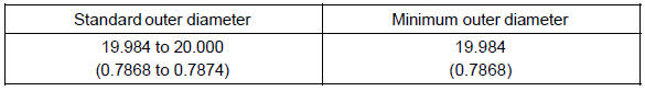
If the outer diameter is less than the minimum, replace the reverse idler gear shaft.
58. REMOVE TRANSMISSION HUB SLEEVE No.3
a. Remove the transmission hub sleeve No.3 from the transmission clutch hub No.3.
 Remove transmission hub sleeve No.3
59. REMOVE SYNCHROMESH SHIFTING KEY SPRING No.3
a. Push the synchromesh shifting key spring No.3 then remove the 2 synchromesh shifting key spring No.3 from the transmission clutch hub No.3.
 Remove synchromesh shifting key spring No.3
60. REMOVE SYNCHRONIZER PULL RING
- Using a screwdriver, remove the synchronizer pull ring snap ring.
- Remove the synchronizer pull ring, synchronizer outer ring No.5, synchronizer inner ring No.5 and synchronizer middle ring No.5 from the synchronizer ring No.5.
 Remove synchronizer pull ring
61. INSPECT TRANSMISSION CLUTCH HUB No.3
- Inspect the sliding condition between transmission clutch hub No.3 and transmission hub sleeve No.3.
- Inspect tip of spline gear on the transmission hub sleeve No.3 for wear.
 Inspect transmission clutch hub No.3
62. INSPECT TRANSMISSION HUB SLEEVE No.3
a. Using vernier calipers, measure the transmission hub sleeve No.3 groove and the thickness of the claw part on gear shift fork No.3, and calculate the clearance.
Standard clearance: 0.15 to 0.35 mm (0.0059 to 0.0138 in.) {A − B}
If the clearance is out of the specification, replace the transmission hub sleeve No.3 and gear shift fork No.3 with the new one.
 Inspect transmission hub sleeve No.3
63. INSPECT 5TH GEAR
a. Using a calipers gauge, measure the inside diameter of the 5th gear.
Inside diameter: mm (in.)
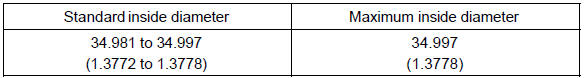
If the inner diameter exceeds the maximum, replace the 5th gear.
64. INSTALL SYNCHRONIZER PULL RING
a. Install the synchronizer middle ring No.5, synchronizer ring outer No.5 and synchronizer pull ring to the synchronizer ring inner No.5. using a screwdriver, fix with snap ring.
 Install synchronizer pull ring
65. INSPECT SYNCHRONIZER RING MIDDLE No.5
a. Check that the synchronizer ring middle No.5 rotates smoothly.
b. Check that the synchronizer ring middle No.5 does not rotate while it is being pushed to the clutch hub No.3.
66. INSTALL SYNCHROMESH SHIFTING KEY SPRING No.3
a. Install the synchromesh shifting key spring No.3 to the transmission clutch hub No.3.
NOTICE: Align the projection of the shifting key spring with the hole of the clutch hub No.3 and install them.
b. Install the synchronizer ring set and synchromesh shifting key spring No.3 to the transmission clutch hub No.3.
NOTICE:
- Engage the shifting key spring claw to the center of the teeth of the synchronizer ring.
- Align the projection of the shifting key spring with the hole of the clutch hub No.3 and install them.
 Install synchromesh shifting key spring No.3
67. INSTALL CONTROL SHAFT COVER BIMETAL FORMED BUSH
a. Using SST, install the shift & select lever shaft bimetal formed bush.
SST 09950−60010 (09951−00180), 09950−70010 (09951−07100)
Clearance: 0.081 to 0.149 mm (0.0032 to 0.0059 in.)
 Install control shaft cover bimetal formed bush
68. INSTALL FRONT TRANSAXLE CASE COVER OIL SEAL
a. Using SST and a hammer, install the front transaxle case cover oil seal.
SST 09316−20011, 09950−60020 (09951−00910), 09950−70010 (09951−07150)
Oil seal driven in depth: 0 0.5 mm (0 0.020 in.)
b. Coat the lip of front transaxle case cover oil seal with MP grease.
 Install front transaxle case cover oil seal
69. INSTALL FR DIFFERENTIAL CASE REAR TAPERED ROLLER BEARING
a. Using SST and a hammer, install the FR differential case rear tapered roller bearing (outer race) to the front transaxle case.
SST 09950−60020 (09951−00910), 09950−70010 (09951−07100)
b. Using SST and press, install the FR differential case rear tapered roller bearing (inner race) to the front differential case.
SST 09950−70010 (09951−07100, 09951−07150), 09608−10010
70. INSTALL FR DIFFERENTIAL CASE FRONT TAPERED ROLLER BEARING
- Install the front differential case shim rear.
- Using SST and a hammer, install FR differential case front
tapered roller bearing (outer race).
SST 09950−60020 (09951−00890), 09950−70010 (09951−07100)
NOTICE: Install the case shim as thick as the removed one.
c. Using SST, remove the FR differential case front tapered roller bearing (inner race) SST 09631−12090, 09950−60010 (09951−00600), 09950−70010 (09951−07100)
71. INSTALL TRANSMISSION CASE OIL SEAL
a. Using SST and a hammer, install the transmission case oil seal to the manual transmission case.
SST 09608−32010, 09950−70010 (09951−07150)
Oil seal driven in depth: 3.5 0.5 mm (0.138 0.020 in.)
b. Coat the lip of transmission case oil seal with MP grease.
 Install transmission case oil seal
72. INSTALL OUTPUT SHAFT REAR BEARING
a. Using SST and a hammer, install the output shaft rear bearing (outer race) to the manual transmission case.
SST 09950−60020 (09951−00680), 09950−70010 (09951−07100)
Clearance: 3.8 to 4.4 mm (0.150 to 0.173 in.)
 Install output shaft rear bearing
73. INSTALL OUTPUT SHAFT (MTM) COVER
a. Coat the output shaft (MTM) cover with MP grease, install it to the manual transaxle case.
NOTICE: Align the projection of the output shaft with the transmission grooves and install them.
 Install output shaft (MTM) cover
74. INSTALL OUTPUT SHAFT FRONT BEARING
a. Using SST and a hammer, install the output shaft front bearing (outer race).
SST 09950−60020 (09951−00730), 09950−70010 (09951−07100)
 Install output shaft front bearing
75. ADJUST OUTPUT SHAFT BEARING PRELOAD
a. Install the output shaft to the manual transaxle case.
b. Install the transmission case with 14 bolts to the manual transaxle case.
Torque: 29 N·m (296 kgf·cm, 21 ft·lbf)
c. Install the 3 bolts to the manual transaxle side.
Torque: 29 N·m (296 kgf·cm, 21 ft·lbf)
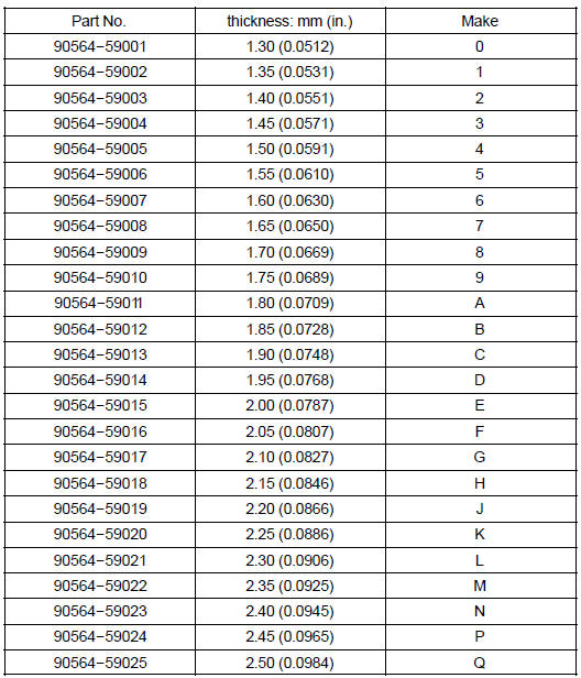
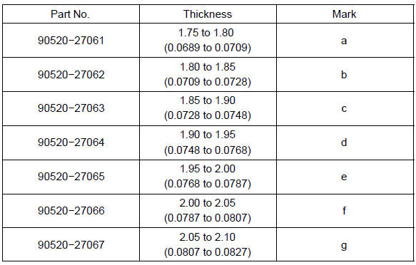
d. Install the output shaft rear bearing shim to the output shaft.
HINT: Install the same thickness of case shim as the removed one.
- Using a torx) socket wrench (T45), install the bearing retainer
RR with 7 screws to the manual transmission case.
Torque: 43 N·m (438 kgf·cm, 32 ft·lbf)
- Install the new output rear set nut to the output shaft.
- Turn the output shaft in both directions to make it smooth.
- Using a socket wrench and torque wrench, inspect the
preload.
Preload: N·m (kgf·cm, in.·lbf)
i. If the preload is out of the specification, select the output shaft rear bearing shim and adjust it.
HINT: The preload of the output shaft rear bearing shim varies in torque from about 0.04 to 0.06 N·m in one size.
Shim: mm (in.)
- Remove the output shaft rear set nut from the output shaft.
- Using a torx) socket wrench (T45), remove the 7 screws and bearing retainer RR from the manual transmission case.
l. Remove the output shaft rear bearing shim from the output shaft.
m. Remove the 3 bolts.
n. Remove the 14 bolts and manual transmission case from the manual transaxle case.
o. Remove the output shaft assy from the front manual transaxle case.
76. ADJUST TAPERED POLLER BEARING PRELOAD
a. Install differential case assy to the manual transaxle case.
b. Install the 14 bolts and manual transmission case to the manual transaxle case.
Torque: 29 N·m (296 kgf·cm, 21 ft·lbf)
- Install the 3 bolts and front manual transaxle case side.
Torque: 29 N·m (296 kgf·cm, 21 ft·lbf)
- Turn the differential case in both directions to make it smooth.
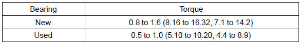
e. Using SST and torque wrench, inspect preload.
SST 09564−32011
Preload: N·m ( kgf·cm, in.·lbf)
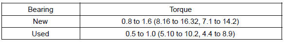
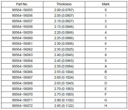
If the preload is out of the specification, select the front differential case shim RR and adjust it.
HINT: The preload of the front differential case shim RR varies in torque from about 0.04 to 0.06 N·m is one size.
Shim: mm (in.)
f. Remove the 3 bolts.
g. Remove the 14 bolts and manual transmission case to the manual transaxle case.
h. Remove the differential case assy from the manual transaxle case.
77. INSTALL FRONT TRANSAXLE CASE OIL SEAL
- Using SST and a hammer, install the front transaxle case
oil seal No.1 to the manual transaxle case.
SST 09950−60010 (09951−00420), 09950−70010 (09951−07150)
- Coat the lip of front transaxle case oil seal No.1 Ωith MP
grease.
Clearance: 1 to 2 mm (0.0394 to 0.0787 in.)
 Install front transaxle case oil seal
78. INSTALL INPUT SHAFT FRONT BEARING
a. Coat the input shaft front bearing with gear oil, install it to the manual transaxle case.
SST 09950−60010 (09951−00570), 09950−70010
(09951−07150)
Clearance: 4.28 to 4.60 mm (0.1685 to 0.1811 in.)
 Install input shaft front bearing
79. INSTALL MANUAL TRANSAXLE CASE RECEIVER
a. Install the 3 bolts and manual transaxle case receiver to the manual transaxle case.
Torque: 7.0 N·m (71 kgf·cm, 62 in.·lbf)
 Install manual transaxle case receiver
80. INSTALL DIFFERENTIAL CASE ASSY
a. Coat the differential case taper roller bearing with gear oil, install the differential case assy to the manual transaxle case.
 Install differential case assy
81. INSTALL OUTPUT SHAFT ASSY
- Apply gear oil to each sliding part of the output shaft assy.
- Lift the differential case assy up with the output shaft assy leaned, and install it to the manual transaxle case.
 Install output shaft assy
82. INSTALL INPUT SHAFT ASSY
- Apply gear oil to each sliding part of the input shaft assy.
- With the output shaft assy leaned, install the input shaft assy to the manual transaxle case.
 Install input shaft assy
83. INSTALL GEAR SHIFT FORK No.2
a. Coat the gear shift fork No.2 Ωith gear oil, install it to the input shaft assy.
 Install gear shift fork No.2
84. INSTALL GEAR SHIFT FORK No.3
- Install the gear shift fork No.3 to the gear shift fork shaft No.3.
- Using a brass bar and hammer, install the 2 shift fork shaft snap rings to the gear shift fork shaft.
c. Apply gear oil to each sliding part of the gear shift fork shaft No.3, install it to the manual transaxle case.
85. INSTALL GEAR SHIFT FORK No.1
a. Apply gear oil to each sliding part of the gear shift fork No.1, install it to the output shaft assy.
 Install gear shift fork No.1
86. INSTALL GEAR SHIFT FORK SHAFT No.2
- Install the gear shift head No.1 to the gear shift fork shaft No.2.
- Apply gear oil to each sliding part of the gear shift fork shaft No.2, install it to the manual transaxle case.
c. Install the 2 shift fork bolts to the gear shift head No.1.
Torque: 24 N·m (245 kgf·cm, 18 ft·lbf)
87. INSTALL REVERSE SHIFT FORK ROLLER
a. Using a magnetic finger, install the reverse shift fork roller to the reverse shift fork.
 Install reverse shift fork roller
88. INSTALL GEAR SHIFT FORK SHAFT No.1
a. Using a brass bar and hammer, install the shift fork shaft snap ring to the shift fork shaft No.1.
b. Install the gear shift fork shaft No.1 to the manual transaxle case.
c. Install the shift fork bolt to the gear shift fork No.1. Torque: 24 N·m (245 kgf·cm, 18 ft·lbf)
89. INSTALL REVERSE SHIFT ARM BRACKET ASSY
a. Install the 2 bolts and reverse shift arm bracket assy to the manual transaxle case.
Torque: 17 N·m (173 kgf·cm, 13 ft·lbf)
 Install reverse shift arm bracket assy
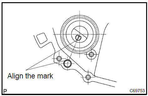
90. INSTALL REVERSE IDLER GEAR SUB−ASSY
a. Coat the reverse idler gear and reverse idler thrust washer with MP grease, install them to the reverse idler gear shaft.
b. Install the reverse idler gear to the manual transaxle case.
HINT: Align the mark of the reverse idler gear shaft with the hole of the bolt.
91. INSTALL TRANSMISSION MAGNET
a. Clean the transmission magnet, install it to the manual transaxle case.
 Install transmission magnet
92. INSTALL REVERSE RESTRICT PIN ASSY
a. Using a pin punch (f 5mm), install the reverse restrict pin and reverse restrict pin assy.
Clearance: 12.5 to 13.5 mm (0.492 to 0.531 in.)
b. Coat the reverse restrict pin plug with adhesive 1324, using hexagon wrench (6mm), install the manual transmission case.
Torque: 13 N·m (133 kgf·cm, 9.6 ft·lbf)
93. INSTALL OIL RECEIVER PIPE No.1 (MTM)
a. Install the bolt and oil receiver pipe No.1 (MTM) to the manual transmission case.
Torque: 17 N·m (173 kgf·cm, 13 ft·lbf)
HINT: Tighten the oil receiver pipe No.1 Ωith the bolt.
 Install oil receiver pipe No.1 (MTM)
94. INSTALL OIL RECEIVER PIPE No.2 (MTM)
a. Install the bolt and oil receiver pipe No.2 (MTM) to the manual transmission case.
Torque: 17 N·m (173 kgf·cm, 13 ft·lbf
)
HINT: Tighten the oil receiver pipe No.2 (MTM) with the bolt while manual transmission case is being put.
 Install oil receiver pipe No.2 (MTM)
95. INSTALL MANUAL TRANSMISSION CASE
a. Apply FIPG bead condition sequentially to the position shown in the diagram of the manual transmission case.
HINT: Install within 10 minutes after applying FIPG.
b. Install the manual transmission case and 14 bolts to the manual transaxle case.
Torque: 29 N·m (296 kgf·cm, 21 ft·lbf)
c. Install the 3 bolts to the manual transaxle case side.
Torque: 29 N·m (296 kgf·cm, 21 ft·lbf)
96. INSTALL CLUTCH TUBE BRACKET No.1
a. Install the clutch tube with 3 bolt brackets.
Torque: 17 N·m (173 kgf·cm, 13 ft·lbf)
97. INSTALL REVERSE IDLER GEAR SHAFT BOLT
a. Coat the bolt with sealant, install new gasket to the manual transmission case with the bolt.
Torque: 30 N·m (306 kgf·cm, 22 ft·lbf)
Sealant: Part No. 08833−00080, THREE BOND 1344, LOCTITE 242 or equivalent
 Install reverse idler gear shaft bolt
98. INSTALL SHIFT FORK SHAFT SHAFT SNAP RING
a. Using a brass bar and hammer, install the shift fork shaft snap ring to the gear shift fork shaft No.1.
b. Using a brass bar and hammer, install the shift fork shaft snap ring to the gear shift fork shaft No.2.
99. INSTALL INPUT SHAFT REAR BEARING SHAFT SNAP RING
a. Using a snap ring expander, install the input shaft rear bearing hole snap ring.
 Install input shaft rear bearing shaft snap ring
100. INSTALL OUTPUT SHAFT REAR BEARING SHIM
a. Install the output shaft rear bearing shim to the output shaft.
HINT: Install a case shim with the same thickness as the removed one.
 Install output shaft rear bearing shim
101. INSTALL BEARING RETAINER REAR (MTM)
a. Coat the bearing retainer rear (MTM) with sealant, install it with a torx) wrench (T45).
Torque: 42 N·m (428 kgf·cm, 31 ft·lbf)
 Install bearing retainer rear (MTM)
102. INSTALL 5TH DRIVEN GEAR
a. Using SST, install the 5th driven gear to the output shaft.
SST 09950−30012 (09951−03010, 09953−03010, 09954−03010, 09956−03030, 09955−03011)
 Install 5th driven gear
103. INSTALL 5TH GEAR NEEDLE ROLLER BEARING
a. Coat the 5th gear needle roller bearing with gear oil, install it to the input shaft.
 Install 5th gear needle roller bearing
104. INSTALL 5TH GEAR
a. Coat the 5th gear with gear oil, install it to the input shaft.
 Install 5th gear
105. INSTALL TRANSMISSION CLUTCH HUB No.3
a. Using SST, install the transmission clutch hub No.3 to the input shaft.
SST 09950−30012 (09951−03010, 09953−03010, 09954−03010)
NOTICE: Align the projection of the synchronizer ring with the hole of the 5th gear and install them.
b. Install the transmission hub sleeve No.3 and gear shift fork No.3 to the transmission clutch hub No.3.
c. Coat the shift fork bolt with sealant, install the gear shift fork No. 3.
Sealant:
Part No. 08833−00080, THREE BOND 1344, LOCTITE
242 or equivalent
Torque: 24 N·m (245 kgf·cm, 18 ft·lbf)
d. Select a snap ring that will allow minimum axial play. Using a brass bar and a hammer, install the shaft snap ring.
Clearance: 0.1 mm or less
Snap ring: mm (in.)

106. INSPECT 5TH GEAR RADIAL CLEARANCE
a. Using a dial indicator, inspect the 5th gear radial clearance.
Standard clearance: 0.009 to 0.050 mm (0.0004 to 0.0020 in.)
If the clearance is out of the specification, replace 1st gear needle roller bearing.
 Inspect 5th gear radial clearance
107. INSPECT 5TH GEAR THRUST CLEARANCE
a. Using a dial indicator, inspect the 5th gear thrust clearance.
Standard clearance: 0.10 to 0.65 mm (0.0039 to 0.0260 in.)
 Inspect 5th gear thrust clearance
108. INSTALL MANUAL TRANSMISSION OUTPUT SHAFT REAR SET NUT
a. Engage the gear double meshing.
b. Install the new manual transmission output shaft rear set nut.
Torque: 123 N·m (1,254 kgf·cm, 91 ft·lbf)
c. Using a chisel and a hammer, stake the manual transmission output shaft rear set nut.
109. INSTALL MANUAL TRANSMISSION CASE COVER SUB−ASSY
a. Apply FIPG to the transaxle case cover sub−assy, as shown in the installation.
FIPG: Part No. 08826−00090, THREE BOND 1281
NOTICE: Install the parts within 10 minutes after applying the packing material (FIPG).
b. Install the transmission case cover sub−assy with 10 bolts to the manual transaxle case.
110. INSTALL DRAIN (MTM) PLUG SUB−ASSY
a. Install the drain plug sub−assy with new gasket to the manual transmission case.
Torque: 49 N·m (500 kgf·cm, 36 ft·lbf)
 Install drain (MTM) plug sub-assy
111. INSTALL MANUAL TRANSMISSION FILLER PLUG
a. Install the manual transmission filler plug with new gasket to the oil seal.
Torque: 49 N·m (500 kgf·cm, 36 ft·lbf)
 Install manual transmission filler plug
112. INSTALL SHIFT & SELECT LEVER SHAFT ASSY
a. Coat the shift & select lever shaft assy with gear oil, install it to the manual transmission case.
 Install shift & select lever shaft assy
113. INSTALL BACK UP LAMP SWITCH ASSY
a. Install back up lamp switch assy to the manual transmission case.
Torque: 40 N·m (408 kgf·cm, 30 ft·lbf)
 Install back up lamp switch assy
114. INSTALL MANUAL TRANSMISSION BREATHER PLUG
a. Install the new gasket with manual transmission breather plug to the manual transmission case.
Torque: 49 N·m (500 kgf·cm, 36 ft·lbf)
 Install manual transmission breather plug
115. INSTALL LOCK BALL ASSY No.1
a. Install the lock ball assy No.1 to the manual transmission case.
Torque: 29 N·m (296 kgf·cm, 21 ft·lbf)
 Install lock ball assy No.1
116. INSTALL CONTROL SHAFT COVER
a. Coat the 4 bolts with sealant, install new gasket with control shaft cover with the bolt.
Sealant:
Part No. 08833−00080, THREE BOND 1344, LOCTITE
242 or equivalent
Torque: 20 N·m (204 kgf·cm, 15 ft·lbf)
 Install control shaft cover
117. INSTALL CONTROL SHIFT LEVER
- Install the control shift lever with shift outer lock pin to the shift & select lever shaft.
- Install the spring washer with the nut.
Torque: 6.4 N·m (65 kgf·cm, 57 in.·lbf)
 Install control shift lever
118. INSTALL SELECTING BELL CRANK ASSY
a. Coat the 2 bolts with sealant, install it with selecting bell crank assy to the manual transmission case.
Sealant:
Part No. 08833−00080, THREE BOND 1344, LOCTITE
242 or equivalent
Torque: 20 N·m (204 kgf·cm, 15 ft·lbf)
 Install selecting bell crank assy
119. INSTALL SPEEDOMETER DRIVEN HOLE COVER SUB−ASSY
a. Install the bolt and speedometer driven hole cover sub−assy to the transmission case.
120. INSTALL CLUTCH RELEASE FORK BOOT
a. Install the clutch release fork bolt to the manual transaxle case.
121. INSTALL RELEASE FORK SUPPORT
a. Using a deep socket wrench, install the release fork support to the manual transaxle case.
Torque: 47 N·m (480 kgf·cm, 35 ft·lbf)
 Install release fork support
122. INSTALL CLUTCH RELEASE BEARING ASSY
- Coat the clutch release bearing assy with release hub grease, install it
to the clutch release fork sub−
assy.
Sealant: Part No. 08887−01806, RELEASE HUB GREASE or equivalent
- Apply clutch spline grease to the input shaft spline.
123. INSTALL CLUTCH RELEASE FORK SUB−ASSY
a. Install the clutch release fork sub − assy to the input shaft.
Manual transaxle system
Manual transaxle assy (From July, 2003)
Manual transaxle assy (E351)
Manual transaxle oil
Front differential oil seal
Floor shift shift lever assy
Input shaft assy (E351)
Output shaft assy (E351)
Floor shift cable transmission control shift
Shift & select lever shaft assy (E351)
Differential case assy (E351)
Floor shift cable transmission control select
Toyota Camry XV30 (2002–2006) Service Manual
- Introduction
- Audio & visual system
- Automatic transmission / trans
- Brake
- Clutch
- Communication system
- Cooling
- Cruise control
- Drive shaft / propeller shaft
- Emission control
- Engine control system
- Engine hood/door
- Engine mechanical
- Exhaust
- Exterior/interior trim
- Front suspension
- Fuel
- Heater & air conditioner
- Ignition
- Instrument panel/meter
- Intake
- Lighting
- Lubrication
- Manual transmission/transaxle
- Parking brake
- Power steering
- Rear suspension
- Seat
- Service specifications
- Sliding roof/convertible
- Starting & charging
- Steering column
- Supplemental restraint system
- Theft deterrent & door lock
- Tire & wheel
- Windshield/windowglass/mirror
- Wiper & washer
- Wiring
Categories
