 Toyota Camry XV30 (2002–2006) Service ManualManual transmission/transaxle
Output shaft assy (E351)
Output shaft assy (E351)
OVERHAUL
1. INSPECT 1ST GEAR THRUST CLEARANCE
a. Using a feeler gauge, measure the 1st gear thrust clearance.
Standard clearance: 0.25 to 0.40 mm (0.0098 to 0.0157 in.)
 Inspect 1st gear thrust clearance
2. INSPECT 2ND GEAR THRUST CLEARANCE
a. Using a dial indicator, measure the 2nd gear thrust clearance.
Standard clearance: 0.10 to 0.35 mm (0.0039 to 0.0138 in.)
 Inspect 2nd gear thrust clearance
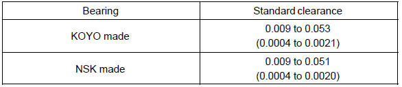
3. INSPECT 1ST GEAR RADIAL CLEARANCE
a. Using a dial indicator, measure the 1st gear radial clearance.
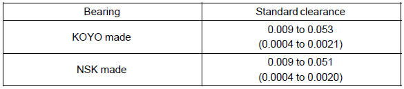
Standard clearance: mm (in.)
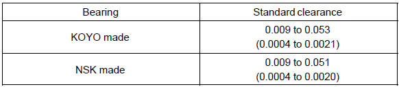
If the clearance is out of the specification, replace the 1st gear needle roller bearing.
 Inspect 1st gear radial clearance
4. INSPECT 2ND GEAR RADIAL CLEARANCE
a. Using a dial indicator, measure the 2nd gear radial clearance.
Standard clearance: mm (in.)
If the clearance is out of the specification, replace the 2nd gear needle roller bearing.
 Inspect 2nd gear radial clearance
5. REMOVE 4TH DRIVEN GEAR
a. Using SST and a press, remove the output shaft bearing rear (inner race) and 4th driven gear.
SST 09950−00020
 Remove 4th driven gear
6. REMOVE OUTPUT GEAR SPACER
a. Remove the output gear spacer from the output shaft.
 Remove output gear spacer
7. REMOVE 2ND GEAR
a. Using SST and a press, remove the 3rd driven gear and 2nd gear from the out put shaft.
SST 09950−00020
 Remove 2nd gear
8. REMOVE SYNCHRONIZER RING SET No.2
a. Remove the synchronizer ring set No.2 from the transmission clutch hub No.1.
 Remove synchronizer ring set No.2
9. REMOVE 2ND GEAR NEEDLE ROLLER BEARING
a. Remove the 2nd gear needle roller bearing from the output shaft.
 Remove 2nd gear needle roller bearing
10. REMOVE 2ND GEAR BEARING SPACER
a. Remove the 2nd gear bearing spacer from the output shaft.
 Remove 2nd gear bearing spacer
11. REMOVE 2ND GEAR BUSH
a. Remove the 2nd gear bush from the output shaft.
 Remove 2nd gear bush
12. REMOVE 2ND GEAR BUSH BALL
a. Using a magnetic finger, remove the 2nd gear bush ball from the output sha
 Remove 2nd gear bush ball
13. REMOVE 1ST GEAR
a. Using SST and a press, remove the transmission clutch hub No.1 and 1st gear from the output shaft.
SST 09950−00020
 Remove 1st gear
14. REMOVE SYNCHRONIZER RING SET No.1
a. Remove the synchronizer ring set No.1 from the 1st gear.
 Remove synchronizer ring set No.1
15. REMOVE 1ST GEAR NEEDLE ROLLER BEARING
a. Remove the 1st gear needle roller bearing from the output shaft.
 Remove 1st gear needle roller bearing
16. REMOVE OUTPUT SHAFT FRONT BEARING
a. Using SST and a press, remove the output shaft front bearing (inner race) from the output shaft.
SST 09950−00020, 09950−60010 (09951−00320), 09950−70010 (09951−07150)
NOTICE: Do not tighten SST excessively.
 Remove output shaft front bearing
17. REMOVE REVERSE GEAR
a. Remove the reverse gear, 3 synchromesh shifting keys and 3 synchromesh shifting key springs from the transmission clutch hub No.1.
 Remove reverse gear
18. INSPECT OUTPUT SHAFT
a. Using V−block and a dial indicator, measure the shaft run out.
Maximum run out: 0.03 mm (0.0012 in.)
If the run out exceeds the maximum, replace the input shaft.
b. Using a micrometer, measure the outer diameter of the output shaft journal surface.Outer diameter: mm (in.)
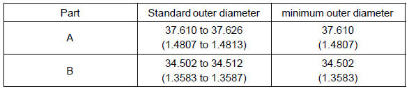
If the outer diameter is less than the minimum, replace the input shaft.
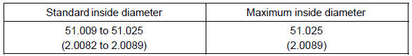
19. INSPECT 2ND GEAR
a. Using a cylinder gauge, measure the inside diameter of the 2nd gear.
Inside diameter: mm (in.)
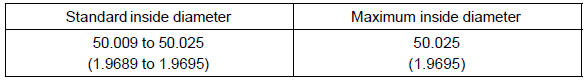
If the inside diameter exceeds the maximum, replace the 2nd gear.
 Inspect 2nd gear
20. INSPECT 1ST GEAR
a. Using a cylinder gauge, measure the inside diameter of the 1st gear.
Inside diameter: mm (in.)
If the inside diameter exceeds the maximum, replace the 1st gear.
 Inspect 1st gear
21. INSPECT SYNCHRONIZER RING SET No.2
a. Coat the cone of the 2nd gear with gear oil, check that it does not turn in the both circumference directions while pushing it to the synchronizer ring No.2.
 Inspect synchronizer ring set No.2
b. Check the clearance between the synchronizer ring No.2 and 2nd gear while pushing it to the synchronizer ring No.2.
Standard clearance: 0.70 to 1.45 mm (0.0276 to 0.0571 in.)
If the standard clearance is out of the specification, replace the synchronizer ring set No.2 Ωith a new one.
22. INSPECT SYNCHRONIZER RING SET No.1
a. Coat the 1st gear cone with gear oil. Turn the synchronizer ring set No.1. in one direction while pushing it to the 1st gear cone. Check that the ring locks.
b. Check the clearance between the synchronizer ring set No.1 and 1st gear while pushing it to the cone of synchronizer ring set No.1.
Standard clearance: 0.70 to 1.45 mm (0.0276 to 0.0571 in.)
If the standard clearance is out of the specification, replace the synchronizer ring set No.1 Ωith a new one.
23. INSPECT REVERSE GEAR
a. Using a vernier calipers, measure the reverse gear groove and thickness of the claw part on gear shift fork No.1, and calculate Standard clearance: 0.15 to 0.35 mm (0.0059 to 0.0138 in.) {A − B}
If the clearance is out of the specification, replace the reverse gear and gear shift fork No.1 Ωith the new one.
 Inspect reverse gear
24. INSPECT TRANSMISSION CLUTCH HUB No.1
- Check the sliding condition between the transmission clutch hub No.1 and reverse gear.
- Check the tip of spline gear on the sleeve of reverse gear for wear.
 Inspect transmission clutch hub No.1
25. INSTALL REVERSE GEAR
- Coat the reverse gear with gear oil.
- Install the 3 synchromesh shifting key spring No.1 and transmission clutch hub No.1 to the reverse gear.
NOTICE: Do not set the reverse gear and the transmission clutch hub No.1 in the incorrect direction.
c. Using a screwdriver, install the synchromesh shifting key No.1 to the reverse gear.
 Install reverse gear
26. INSTALL OUTPUT SHAFT FRONT BEARING
a. Using SST and a press, install the output shaft front bearing (inner race) to the output shaft.
SST 09950−60010 (09951−00430), 09950−70010 (09951−07150)
 Install output shaft front bearing
27. INSTALL SYNCHRONIZER RING SET No.1
a. Coat the synchronizer ring set No.1 Ωith gear oil, install it to the 1st gear.
NOTICE: Align the synchronizer ring set No.1 Ωith the hole of 1st gear and install.
 Install synchronizer ring set No.1
28. INSTALL 1ST GEAR NEEDLE ROLLER BEARING
a. Coat the 1st gear needle roller bearing with gear oil, install it to the output shaft.
 Install 1st gear needle roller bearing
29. INSTALL 1ST GEAR
a. Coat the 1st gear with gear oil, install it to the output shaft.
 Install 1st gear
30. INSTALL TRANSMISSION CLUTCH HUB No.1
a. Using SST and a press, install transmission clutch hub No.1 to the output shaft.
SST 09316−60011 (09316−00031), 09950−60010 (09951−00320), 09950−70010 (09951−07100)
NOTICE:
- Align the synchronizer ring No.1 Ωith synchromesh shifting key No.1 and install.
- Make sure that the 1st gear rotates.
 Install transmission clutch hub No.1
31. INSTALL 2ND GEAR BUSH BALL
a. Coat the gear bush with MP grease, install it to the output shaft.
 Install 2nd gear bush ball
32. INSTALL 2ND GEAR BUSH
a. Coat the 2nd gear bush with gear oil, install it to the output shaft.
 Install 2nd gear bush
33. INSTALL 2ND GEAR BEARING SPACER
a. Coat the 2nd gear bearing spacer with gear oil, install it to the output shaft.
 Install 2nd gear bearing spacer
34. INSTALL 2ND GEAR NEEDLE ROLLER BEARING
a. Coat the 2nd gear needle roller bearing with gear oil, install it to the output shaft.
 Install 2nd gear needle roller bearing
35. INSTALL SYNCHRONIZER RING SET No.2
a. Coat the synchronizer ring set No.2 Ωith gear oil, install it to the transmission clutch hub No.1
NOTICE: Align the key groove on the synchronizer ring set No.2 Ωith the synchromesh shifting key No.1.
 Install synchronizer ring set No.2
36. INSTALL 2ND GEAR
a. Coat the 2nd gear with gear oil, install it to the output shaft.
 Install 2nd gear
37. INSTALL 3RD DRIVEN GEAR
a. Using SST and a press, install the 3rd driven gear to the output shaft.
SST 09608−00071, 09950−60010 (09951−00320), 09950−70010 (09951−07100)
 Install 3rd driven gear
38. INSTALL OUTPUT GEAR SPACER
a. Install the output gear spacer to the output shaft.
 Install output gear spacer
39. INSTALL 4TH DRIVEN GEAR
a. Using SST and a press, install the 4th driven gear to the output shaft.
SST 09608−00071, 09950−60010 (09951−00320), 09950−70010 (09951−07100)
 Install 4th driven gear
40. INSTALL OUTPUT SHAFT FRONT BEARING
a. Using SST and a press, install the output shaft front bearing (inner race) to the output shaft.
SST 09506−30012, 09950−60010 (09951−00320), 09950−70010 (09951−07100)
 Install output shaft front bearing
41. INSPECT 2ND GEAR RADIAL CLEARANCE
a. Using a dial indicator, measure the 2nd gear radial clearance.
Standard clearance: mm (in.)
If the clearance is out of the specification, replace the 2nd gear needle roller bearing.
 Inspect 2nd gear radial clearance
42. INSPECT 1ST GEAR RADIAL CLEARANCE
a. Using a dial indicator, measure the 1st gear radial clearance.
Standard clearance: mm (in.)

If the clearance is out of the specification, replace the 1st gear needle roller bearing.
 Inspect 1st gear radial clearance
43. INSPECT 2ND GEAR THRUST CLEARANCE
a. Using a dial indicator, measure the 2nd gear thrust clearance.
Standard clearance: 0.10 to 0.35 mm (0.0039 to 0.0138 in.)
 Inspect 2nd gear thrust clearance
44. INSPECT 1ST GEAR THRUST CLEARANCE
a. Using a feeler gauge, measure the 1st gear thrust clearance.
Standard clearance: 0.25 to 0.40 mm (0.0098 in. to 0.0157 in.)
 Inspect 1st gear thrust clearance
Manual transaxle system
Manual transaxle assy (From July, 2003)
Manual transaxle assy (E351)
Manual transaxle oil
Front differential oil seal
Floor shift shift lever assy
Input shaft assy (E351)
Output shaft assy (E351)
Floor shift cable transmission control shift
Shift & select lever shaft assy (E351)
Differential case assy (E351)
Floor shift cable transmission control select
Toyota Camry XV30 (2002–2006) Service Manual
- Introduction
- Audio & visual system
- Automatic transmission / trans
- Brake
- Clutch
- Communication system
- Cooling
- Cruise control
- Drive shaft / propeller shaft
- Emission control
- Engine control system
- Engine hood/door
- Engine mechanical
- Exhaust
- Exterior/interior trim
- Front suspension
- Fuel
- Heater & air conditioner
- Ignition
- Instrument panel/meter
- Intake
- Lighting
- Lubrication
- Manual transmission/transaxle
- Parking brake
- Power steering
- Rear suspension
- Seat
- Service specifications
- Sliding roof/convertible
- Starting & charging
- Steering column
- Supplemental restraint system
- Theft deterrent & door lock
- Tire & wheel
- Windshield/windowglass/mirror
- Wiper & washer
- Wiring
Categories
