 Toyota Camry XV30 (2002–2006) Service ManualEngine mechanical
Camshaft (2AZ−FE)(From July, 2003)
Camshaft (2AZ−FE)(From July, 2003)
REPLACEMENT
- REMOVE FRONT WHEEL RH
- REMOVE FRONT FENDER APRON SEAL RH
- REMOVE ENGINE COVER SUB−ASSY No.1
- REMOVE SPARK PLUG
- DISCONNECT VENTILATION HOSE
- DISCONNECT VENTILATION HOSE No.2
- DISCONNECT ENGINE WIRE
- REMOVE CYLINDER HEAD COVER SUB−ASSY
- Remove the bolt and disconnect the engine wire harness clamp.
- Remove the bolts, 2 nuts, cylinder head cover and gasket.
 Remove cylinder head cover sub-assy
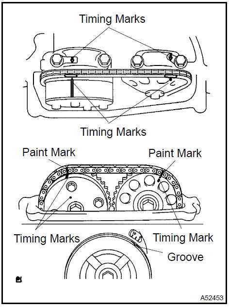
9. SET No. 1 CYLINDER TO TDC/COMPRESSION
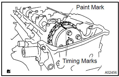
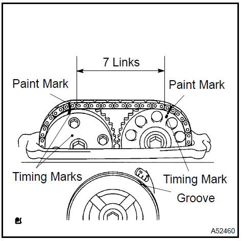
- Turn the crankshaft pulley, and align its groove with the timing mark 0 of the timing chain cover.
- Check that the timing marks of the camshaft timing gear and camshaft timing sprocket are aligned with the timing marks of the bearing cap as shown in the illustration.
- Place a paint mark on the timing chain.
 Set No. 1 Cylinder to TDC/compression
10. REMOVE CHAIN TENSIONER ASSY No.1
a. Remove the 2 nuts, tensioner and gasket.
NOTICE: Be sure not to revolve the crankshaft without the tensioner.
 Remove chain tensioner assy No.1
11. REMOVE CAMSHAFT SUB−ASSY, No.2
a. Fix the camshaft with a wrench and then loosen the sprocket bolt.
NOTICE: Be careful not to damage the valve lifter.
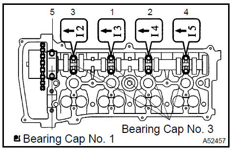
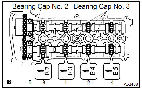
b. Uniformly loosen and remove the No. 2 camshaft’s 10 bearing cap bolts in the sequence shown in the illustration.
Then remove the 5 bearing caps.
- Raise the No. 2 camahaft and remove it. Then remove the sprocket bolt.
- Remove the timing chain sprocket and the timing chain from the No. 2 camshaft.
- Remove the camshaft timing sprocket from the timing chain.
12. REMOVE CAMSHAFT
- Uniformly loosen and remove the camshaft’s 10 bearing cap bolts in the sequence shown in the illustration. Then remove the 5 bearing caps.
- Remove the camshaft.
c. Tie the timing chain with a string.
NOTICE: Do not drop anything inside the timing chain cover.
13. REMOVE CAMSHAFT TIMING GEAR ASSY
- Fix the No. 1 camshaft with a vise, and make sure that the camshaft timing gear does not rotate.
- Cover all the paths with vinyl tape except the advanced side path shown in the illustration.
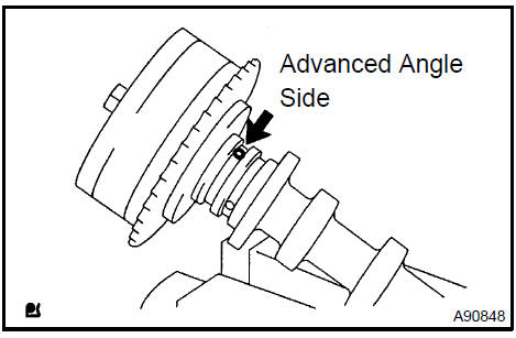
c. Using an air gun, apply about 150 kPA (1.5kgf/cm), 21 psi) of air pressure to the port on the advanced angle side.
CAUTION: Some oil spraying will occur. Contain the spray with a shop rag.
HINT: This operation releases the lock pin for the extreme retarded angle lock.
d. Under the condition above, check that the camshaft timing gear can be turned by hand to the advanced angle side (counterclokΩise), the direction of the arrow in the illustration.
Standard: Must turn
HINT: The camshaft timing gear will turn to the advanced angle side without applying foce by hand depending on the force of the air pressure applied. Also, if applying pressure to the oil path is difficult as a result of air leakage from the port, the lock−pin may be difficult to release.
e. Remove the fringe bolt from the camshaft timing gear.
NOTICE:
- Be sure not to remove the other 4 bolts.
- If planning to reuse the camshaft timing gear assembly, release the straight pin lock first, and then install the gear.
14. INSTALL CAMSHAFT TIMING GEAR ASSY
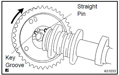
- Put the camshaft timing gear and the camshaft together with the straight pin and key groove.
- Turn the camshaft timing gear (as shown in the illustration) while pushing it lightly against the camshaft. Push further at the position where the pin gets into the groove.
NOTICE: Be sure not to turn the camshaft timing gear to the retarded angle side (to the right direction).
- Check that there is no clearance between the gear’s fringe and the camshaft.
- Tighten the fringe bolt with the camshaft timing gear fixed.
Torque: 54 N·m (551 kgf·cm, 40 ft·lbf)
- Check that the camshaft timing gear can move to the retarded angle side (to the right direction) and is locked at the extrene retard angleed position.
 Install camshaft timing gear assy
15. INSTALL CAMSHAFT
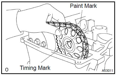
a. Install the timing chain on the camshaft timing gear, with the painted mark of the link aligned with the timing marks of the camshaft timing sprocket.
b. Examine the front marks and unmbers of the 5 bearing caps and install them. Then install the 10 bearing cap bolts. Uniformly tighten the bolts in the sequence shown in the illustration.
Torque: 30 N·m (301 kgf·cm, 22 ft·lbf) for bearing cap No. 1 9.0 N·m (92 kgf·cm, 80 in.·lbf) for bearing cap No. 3
16. INSTALL No.2 CAMSHAFT
a. Put the camshaft on the cylinder head with the painted mark of the link of chain aligned with the timing mark of the camshaft timing sprocket.
b. Raising the camshaft, temporarily tighten the sprocket bolt.
c. Examine the front marks and unmbers of the 5 bearing caps and install them. Then install the 10 bearing cap bolts. Uniformly tighten the bolts in the sequence shown in the illustration.
Torque: 30 N·m (301 kgf·cm, 22 ft·lbf) for bearing cap No. 2 9.0 N·m (92 kgf·cm, 80 in.·lbf) for bearing cap No. 3
d. Fix the camshaft with a wrench, and then tighten the sprocket bolt.
Torque: 54 N·m (551 kgf·cm, 40 ft·lbf)
NOTICE: Be careful not to damage the valve lifter.
e. As shown in the illustration, check the paint marks of the timing chain, camshaft timing gear and camshaft timing sprocket and the alignment of the pulley groove with timing mark of the chain cover.
17. INSTALL CHAIN TENSIONER ASSY No.1
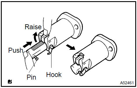
a. Release the ratchet pawl, fully push in the plunger and apply the hook to the pin so that the plunger cannot spring out.
b. Install a new gasket and the chain tensioner with the 2 nuts.
Torque: 9.0 N·m (92 kgf·cm, 80 in.·lbf)
NOTICE: When installing the tensioner, set the hook again if the hook releases the plunger.
c. Turn the crankshaft counterclockΩise and check that the plunger knock pin is disconnected from the hook.
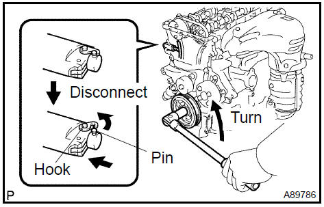
d. Turn the crankshaft clockΩise and check that the slipper is pushed by the plunger.
18. INSTALL CYLINDER HEAD COVER SUB−ASSY
- Remove any old packing (FIPG) material.
- Apply seal packing to 2 locations as shown in the illustration.
Seal packing: Part No. 08826−00080 or equivalent
NOTICE:
- Remove any oil the contact surface.
- Install the cylinder head cover within 5 minutes after applying seal packing.
- Do not apply engine oil for at least 2 hours after installing.
c. Install the cylinder head cover with the 8 bolts and 2 nuts.
Torque: 11 N·m (110 kgf·cm, 8 ft·lbf)
- CONNECT ENGINE WIRE
- INSTALL SPARK PLUG Torque: 19 N·m (194 kgf·cm, 14 ft·lbf)
- INSTALL FRONT WHEEL RH Torque: 103 N·m (1,050 kgf·cm, 76 ft·lbf)
- INSPECT OIL LEAK
Engine (2AZ−FE) (From July, 2003)
Timing gear case or timing chain case oil seal (2AZ−FE)(From July, 2003)
Engine rear oil seal (2AZ−FE)(From July, 2003)
Cylinder head assy (2AZ−FE) (From July, 2003)
Cylinder block assy (2AZ−FE)(From July, 2003)
Engine (1MZ−FE/3MZ−FE)
Drive belt (1MZ−FE/3MZ−FE)
Valve clearance (1MZ−FE/3MZ−FE)
Partial engine assy (1MZ−FE/3MZ−FE)
Partial engine assy (2AZ−FE)(From July, 2003)
Partial engine assy (1MZ−FE/3MZ−FE)
Timing belt (1MZ−FE/3MZ−FE)
Camshaft (RH BANK) (1MZ−FE/3MZ−FE)
Camshaft (LH BANK) (1MZ−FE/3MZ−FE)
Cylinder head gasket (1MZ−FE/3MZ−FE)
Cylinder head gasket No.2 (1MZ−FE/3MZ−FE)
Oil pump seal (1MZ−FE/3MZ−FE)
Engine rear oil seal (1MZ−FE/3MZ−FE)
Cylinder head assy (1MZ−FE/3MZ−FE)
Cylinder block assy (1MZ−FE/3MZ−FE)
Partial engine assy (2AZ−FE)(From July, 2003)
Drive belt (2AZ−FE)(From July, 2003)
Valve clearance (2AZ−FE)
Chain (2AZ−FE)(From July, 2003)
Camshaft (2AZ−FE)(From July, 2003)
Cylinder head gasket (2AZ−FE)(From July, 2003)
Toyota Camry XV30 (2002–2006) Service Manual
- Introduction
- Audio & visual system
- Automatic transmission / trans
- Brake
- Clutch
- Communication system
- Cooling
- Cruise control
- Drive shaft / propeller shaft
- Emission control
- Engine control system
- Engine hood/door
- Engine mechanical
- Exhaust
- Exterior/interior trim
- Front suspension
- Fuel
- Heater & air conditioner
- Ignition
- Instrument panel/meter
- Intake
- Lighting
- Lubrication
- Manual transmission/transaxle
- Parking brake
- Power steering
- Rear suspension
- Seat
- Service specifications
- Sliding roof/convertible
- Starting & charging
- Steering column
- Supplemental restraint system
- Theft deterrent & door lock
- Tire & wheel
- Windshield/windowglass/mirror
- Wiper & washer
- Wiring
Categories
