 Toyota Camry XV30 (2002–2006) Service ManualEngine mechanical
Cylinder head assy (1MZ−FE/3MZ−FE)
Cylinder head assy (1MZ−FE/3MZ−FE)
COMPONENTS
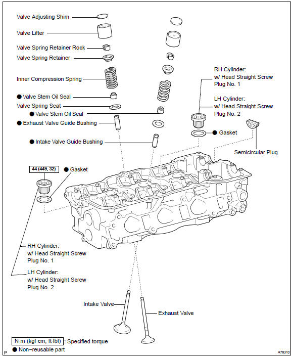
OVERHAUL
1. REMOVE W/HEAD STRAIGHT SCREW PLUG No.1 (RH CYLINDER)
a. Using a straight hexagon wrench 14, remove the 2 screw plugs.
2. REMOVE W/HEAD STRAIGHT SCREW PLUG No.2 (LH CYLINDER)
a. Using a straight hexagon wrench 14, remove the 2 screw plugs.
3. REMOVE VALVE LIFTER
HINT: Store the lifters in correct order so that they can be returned to the original locations when reassembling.
4. REMOVE INTAKE VALVE
a. Using SST, compress the valve spring and remove the 2 keepers, retainer, spring and valve.
SST 09202−70020 (09202−00010)
HINT: Store the valves, valve springs, spring seats and spring retainers in correct order so that they can be returned to the original locations when reassembling.
Remove intake valve
5. REMOVE EXHAUST VALVE
a. Using SST, compress the valve spring and remove the 2 keepers, retainer, spring and valve.
SST 09202−70020 (09202−00010)
HINT: Store the valves, valve springs, spring seats and spring retainers in correct order so that they can be returned to the original locations when reassembling.
Remove exhaust valve
6. REMOVE VALVE STEM OIL O SEAL OR RING
a. Using needle−nose pliers, remove the oil seal.
-
REMOVE VALVE SPRING SEAT
-
REMOVE SEMICIRCULAR PLUG
-
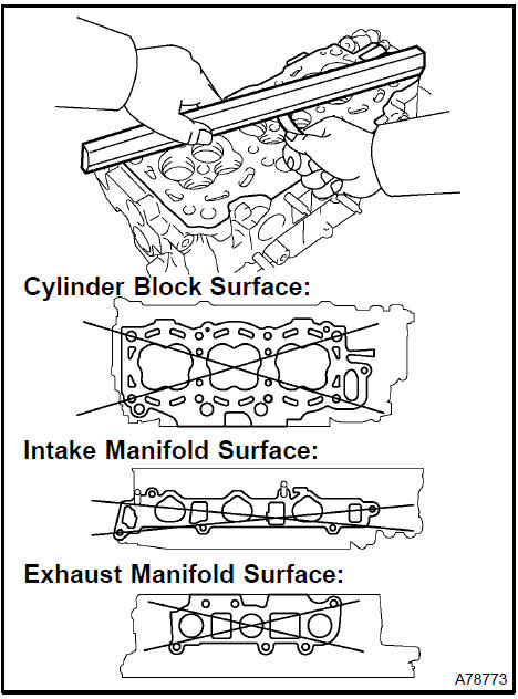
INSPECT CYLINDER HEAD FOR FLATNESS
a. Using a precision straight edge and a feeler gauge, measure the surface contacting the cylinder block and the manifolds for warpage.
Maximum warpage:
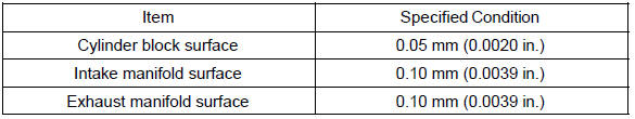
If the warpage is greater than the maximum, replace the cylinder head.
10. INSPECT CYLINDER HEAD FOR CRACKS
a. Using a dye penetrate, check the combustion chamber, intake ports, exhaust ports and cylinder block surface for cracks.
If cracked, replace the cylinder head.
Inspect cylinder head for cracks
11. INSPECT INTAKE VALVE
a. Check the valve overall length.
Specified overall length: 94.95 − 95.45 mm (3.7382 − 3.7579 in.)
If the overall length is less than the minimum, replace the valve.
b. Using a micrometer, measure the diameter of the valve stem.
Valve stem diameter: 5.470 to 5.485 mm (0.2154 to 0.2159 in.)
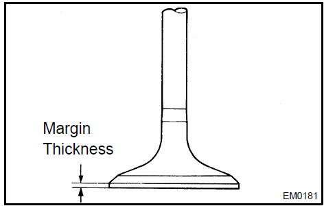
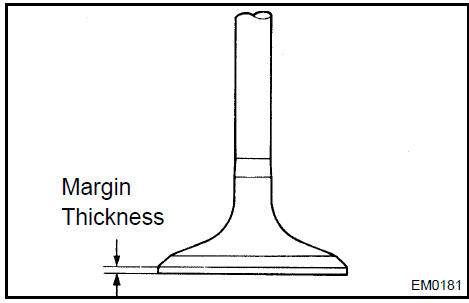
c. Check the valve head margin thickness.
Specified margin thickness: 0.5 − 1.0 mm (0.020 − 0.039 in.)
If the margin thickness is less than the minimum, replace the valve.
12. INSPECT EXHAUST VALVE
a. Check the valve overall length.
Specified overall length: 94.90 − 95.40 mm (3.7362 − 3.7559 in.)
If the overall length is less than the minimum, replace the valve.
b. Using a micrometer, measure the diameter of the valve stem.
Valve stem diameter: 5.465 to 5.480 mm (0.2152 to 0.2157 in.)
c. Check the valve head margin thickness.
Specified margin thickness: 0.5 − 1.0 mm (0.020 − 0.039 in.)
If the margin thickness is less than the minimum, replace the valve.
13. INSPECT INNER COMPRESSION SPRING
a. Using a vernier caliper, measure the free length of the valve spring.
Free length: 45.50 mm (1.7913 in.)
If the free length is not as specified, replace the valve spring.
b Using steel squares, measure the deviation of the valve spring.
Maximum deviation: 2.0 mm (0.079 in.)
If the deviation is greater than the maximum, replace the valve spring.
c. Using a spring tester, measure the tension of the valve spring at the specified installed length.
Installed tension: 86 to 206 N (19.0 to 21.0 kgf, 41.9 to 46.3 lbf) at 33.8 mm (1.331 in.)
If the installed tension is not as specified, replace the valve spring.
14. INSPECT VALVE GUIDE BUSHING OIL CLEARANCE
-
Using a caliper gauge, measure the inside diameter of the guide bushing.
Bushing inside diameter: 5.510 to 5.530 mm (0.2169 to 0.2177 in.)
-
Subtract the valve stem diameter measurement from the guide bushing inside diameter measurement.
Specified oil clearance:
If the clearance is greater than the maximum, replace the valve and guide bushing.
15. REMOVE VALVE GUIDE BUSHING
a. Heat the cylinder head to approximately 80 to 100 C(176 to 212 F).
b. Using SST and a hammer, tap out the guide bushing.
SST 09201−10000, 09201−01055, 09950−70010 (09951−07100)
16. INSTALL VALVE GUIDE BUSHING
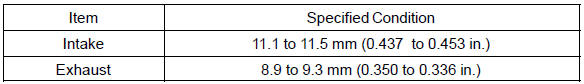
a. Using a caliper gauge, measure the bushing bore diameter of the cylinder head.
Diameter: 10.295 to 10.313 mm (0.4053 to 0.4060 in.)
If the bushing bore diameter of the cylinder head is greater than 10.313 mm (0.4060 in.), machine the bushing bore to the dimension of 10.345 to 10.363 mm (0.4073 to 0.4080 in.).
Bushing diameter:
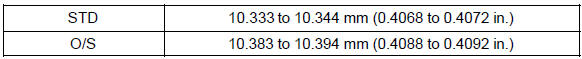
HINT: Different the bushes are used for the intake and exhaust.
Bushing length:

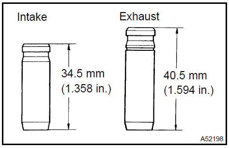
-
Heat the cylinder head to approximately 80 to 100 C (176 to 212 F)
-
Using SST and a hammer, tap in a new guide bushing to the specified protrusion height.
SST 09201−10000, 09201−01055, 09950−70010 (09951−07100)
Protrusion height:
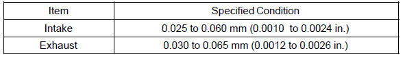
d. Using a sharp 5.5 mm reamer, ream the guide bushing to obtain the standard specified clearance between the guide bushing and the valve stem.
Standard oil clearance:
17. INSPECT VALVE SEATS
-
Apply a light coat of prussian blue (or white lead) to the valve face.
-
Lightly press the valve against the seat.
NOTICE: Do not rotate the valve.
c. Check the valve face and valve seat according to the following procedure.
-
If blue appears 360 around the valve face, the valve face is concentric. If not, replace the valve.
-
If blue appears 360 around the valve seat, the guide and valve face are concentric. If not, resurface the valve seat.
-
Check that the valve seat contact is in the middle of the valve face with the width between 1.0 to 1.4 mm (0.039 to 0.055 in.).
Inspect valve seats
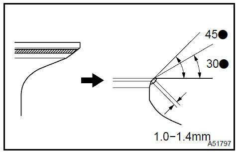
18. REPAIR VALVE SEATS
NOTICE: Releasing the seat−cutter pressure gradually helps to make smoother valve seat faces
.
a. If the seating is too high on the valve face, use 30 and 45 cutters to correct the seat.
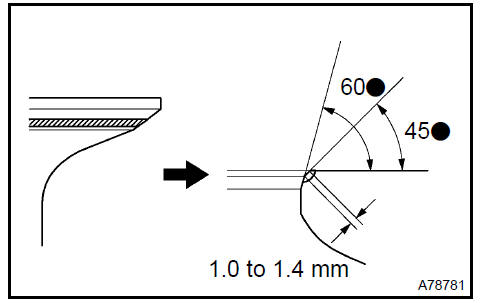
-
If the seating is too low on the valve face, use 60 and 45 cutters to correct the seat.
-
Handrub the valve and valve seat with an abrasive compound.
-
Recheck the valve seating position.
19. INSPECT VALVE LIFTER
a. Using a micrometer, measure the lifter diameter.
Lifter diameter: 30.966 to 30.976 mm (1.2191 to 1.2195 in.)
Inspect valve lifter
20. INSPECT VALVE LIFTER OIL CLEARANCE
a. Using a caliper gauge, measure the lifter bore diameter of the cylinder head.
Lifter bore diameter: 31.009 to 31.025 mm (1.2208 to 1.2215 in.)
b. Subtract the lifter diameter measurement from the lifter bore diameter measurement.
Specified oil clearance: 0.033 to 0.070 mm (0.0013 to 0.0028 in.)
If the oil clearance is greater than the maximum, replace the lifter.
If necessary, replace the cylinder head.
21. INSPECT CAMSHAFT GEAR BACKLASH
-
Install the camshaft timing gear assembly.
-
Install the camshafts to the cylinder head.
NOTICE:
-
Install without valves and sub−gear.
-
Install with its timing mark matched.
-
Set the dial indicator to the teeth of the intake camshaft at a right angle (90 ).
-
Measure the backlash of the camshaft timing gear at least 4 positions.
Specified backlash: 0.020 to 0.300 mm (0.0008 to 0.0118 in.)
If the backlash is greater than the maximum, replace the camshafts.
22. INSPECT CAMSHAFT THRUST CLEARANCE
-
Install the camshafts.
-
Using a dial indicator, measure the thrust clearance while moving the camshaft back and forth.
Specified thrust clearance: 0.040 to 0.120 mm (0.0016 to 0.0047 in.)
If the thrust clearance is greater than the maximum, replace the camshaft. If necessary, replace the bearing caps and cylinder head together.
Inspect camshaft thrust clearance
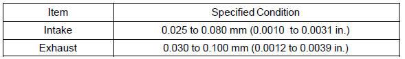
23. INSPECT CAMSHAFT OIL CLEARANCE
-
Clean the bearing caps and camshaft journals.
-
Place the camshafts on the cylinder head.
-
Lay a strip of plastigage across each of the camshaft journal.
-
Install the bearing caps.
Torque: 16 N·m (163 kgf·cm, 12 ft·lbf)
NOTICE: Do not turn the camshaft.
e. Remove the bearing caps.
f. Measure the plastigage at its widest point.
Specified oil clearance: 0.025 to 0.100 mm (0.0010 to 0.0039 in.)
If the oil clearance is greater than the maximum, replace the camshaft. If necessary, replace the bearing caps and cylinder head together.
NOTICE: Completely remove the plastigage.
24. INSTALL RING W/HEAD PIN (RH CYLINDER)
a. Using a plastic−faced hammer, tap in a new ring pin to the specified protrusion height.
Protrusion height: 3 mm (0.12 in.)
 Install ring W/head pin (RH cylinder)
25. INSTALL RING PIN (LH CYLINDER)
a. Using a plastic−faced hammer, tap in a new ring pin to the specified protrusion height.
Protrusion height: 3 mm (0.12 in.)
Install ring pin (LH cylinder)
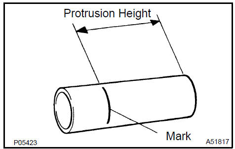
26. INSTALL SPARK PLUG TUBE
a. Using paint, mark the standard position from the edge.
Standard protrusion height: 42.4 to 43.4 mm (1.669 to 1.709 in.)
HINT: Use either end of the spark plug tube.
b. Apply adhesive to the spark plug tube where it will be pressed into the cylinder head.
Adhesive: Part No. 08833−00070 THREE BOND 1324 or equivalent
NOTICE:
-
Install the spark plug tube within 3 minutes after applying adhesive.
-
Do not deform the spark plug tube.
-
Do not expose the seal to coolant for at least 1 hour after installing.
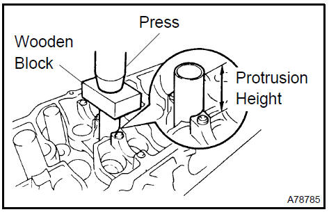
c. Using a press and wooden block, install the spark plug tube to the required protrusion height.
NOTICE: Be careful not to drip the adhesive.
27. INSTALL PCV PIPE
a. Using a wooden block and hammer, tap in 2 new PCV pipes until its top edge is flush with the cylinder head edge.
NOTICE: Be careful not to damage the cylinder head edge.
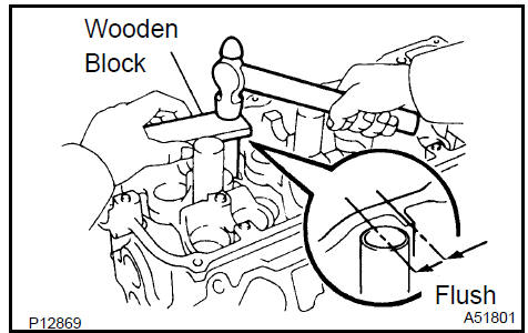
Install PCV pipe
28. INSTALL STUD BOLT
a. Install the stud bolts on the intake side.
Torque: 7.5 N·m (76 kgf·cm, 66 in.·lbf)
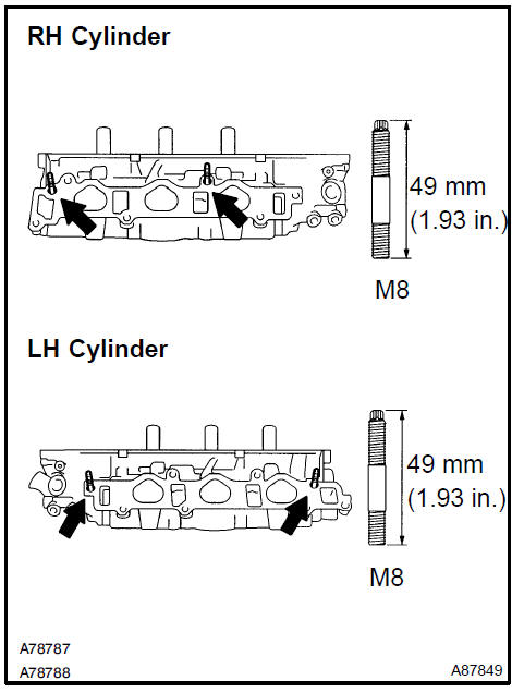
Install stud bolt
29. INSTALL STUD BOLT
a. Install the stud bolts on the exhaust side.
Torque: 20 N·m (199 kgf·cm, 14 ft·lbf)
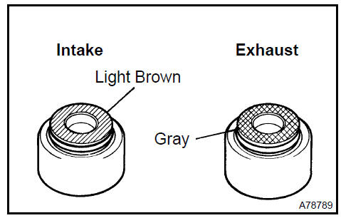
30. INSTALL VALVE STEM OIL O SEAL OR RING
a. Apply a light coat of engine oil on the valve stem.
NOTICE: Pay close attention when installing the intake and exhaust oil seals. For example, installing the intake oil seal into the exhaust or installing the exhaust oil seal to the intake can cause installation problems later.
HINT: The intake valve oil seal is light brown and the exhaust valve oil seal is gray.
b. Using SST, push in a new oil seal.
SST 09201−41020
NOTICE: Failure to use SST will cause the seal to be damaged or improperly seated.
31. INSTALL INTAKE VALVE
a. Install the valve, spring seat, valve spring and spring retainer.
NOTICE: Install the same part in the same combination to the original locations.
b. Using SST, compress the valve spring and place the 2 keepers around the valve stem.
SST 09202−70020 (09202−00010)
c. Using a plastic−faced hammer and a discarded valve with its tip wrapped in tape, lightly tap the installed valve to ensure that it is securely fit.
NOTICE: Be careful not to damage the installed valve stem tip.
32. INSTALL EXHAUST VALVE
a. Install the valve, spring seat, valve spring and spring retainer.
NOTICE: Install the same parts in the same combination to the original locations.
b. Using SST, compress the valve spring and place the 2 keepers around the valve stem.
SST 09202−70020 (09202−00010)
c. Using a plastic−faced hammer and a discarded valve with its tip wrapped in tape, lightly tap the installed valve to ensure that it is securely fit.
NOTICE: Be careful not to damage the installed valve stem tip.
33. INSTALL VALVE LIFTER
a. Apply a light coat of engine oil on the valve lifter.
NOTICE: Install the same part in the same combination to the original locations.
-
Install the valve lifter.
-
Check that the valve lifter rotates smoothly by hand.
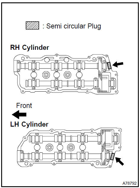
34. INSTALL SEMICIRCULAR PLUG
-
Remove any old seal packing (FIPG) material.
-
Apply seal packing to the semi circular plug grooves.
Seal packing: Part No. 08826−00080 or equivalent
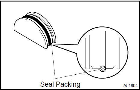
c. Install the 2 semi circular plugs to the cylinder heads.
NOTICE:
-
Install the plugs so that it is flush with the top of the cylinder head.
-
Install the semi circular plugs within 3 minutes after applying seal packing.
-
Do not expose the seal to engine oil for at least 2 hours after installing.
35. INSTALL W/HEAD STRAIGHT SCREW PLUG No.2
a. Using a straight hexagon wrench 14, install 2 new gaskets and the 2 screw plugs.
Torque: 44 N·m (449 kgf·cm, 32 ft·lbf)
36. INSTALL W/HEAD STRAIGHT SCREW PLUG No.1
a. Using a straight hexagon wrench 14, install 2 new gaskets and the 2 screw plugs.
Torque: 44 N·m (449 kgf·cm, 32 ft·lbf)
Engine (2AZ−FE) (From July, 2003)
Timing gear case or timing chain case oil seal (2AZ−FE)(From July, 2003)
Engine rear oil seal (2AZ−FE)(From July, 2003)
Cylinder head assy (2AZ−FE) (From July, 2003)
Cylinder block assy (2AZ−FE)(From July, 2003)
Engine (1MZ−FE/3MZ−FE)
Drive belt (1MZ−FE/3MZ−FE)
Valve clearance (1MZ−FE/3MZ−FE)
Partial engine assy (1MZ−FE/3MZ−FE)
Partial engine assy (2AZ−FE)(From July, 2003)
Partial engine assy (1MZ−FE/3MZ−FE)
Timing belt (1MZ−FE/3MZ−FE)
Camshaft (RH BANK) (1MZ−FE/3MZ−FE)
Camshaft (LH BANK) (1MZ−FE/3MZ−FE)
Cylinder head gasket (1MZ−FE/3MZ−FE)
Cylinder head gasket No.2 (1MZ−FE/3MZ−FE)
Oil pump seal (1MZ−FE/3MZ−FE)
Engine rear oil seal (1MZ−FE/3MZ−FE)
Cylinder head assy (1MZ−FE/3MZ−FE)
Cylinder block assy (1MZ−FE/3MZ−FE)
Partial engine assy (2AZ−FE)(From July, 2003)
Drive belt (2AZ−FE)(From July, 2003)
Valve clearance (2AZ−FE)
Chain (2AZ−FE)(From July, 2003)
Camshaft (2AZ−FE)(From July, 2003)
Cylinder head gasket (2AZ−FE)(From July, 2003)
Toyota Camry XV30 (2002–2006) Service Manual
- Introduction
- Audio & visual system
- Automatic transmission / trans
- Brake
- Clutch
- Communication system
- Cooling
- Cruise control
- Drive shaft / propeller shaft
- Emission control
- Engine control system
- Engine hood/door
- Engine mechanical
- Exhaust
- Exterior/interior trim
- Front suspension
- Fuel
- Heater & air conditioner
- Ignition
- Instrument panel/meter
- Intake
- Lighting
- Lubrication
- Manual transmission/transaxle
- Parking brake
- Power steering
- Rear suspension
- Seat
- Service specifications
- Sliding roof/convertible
- Starting & charging
- Steering column
- Supplemental restraint system
- Theft deterrent & door lock
- Tire & wheel
- Windshield/windowglass/mirror
- Wiper & washer
- Wiring
Categories
