 Toyota Camry XV30 (2002–2006) Service ManualEngine mechanical
Partial engine assy (2AZ−FE)(From July, 2003)
Partial engine assy (2AZ−FE)(From July, 2003)
REPLACEMENT
-
WORK FOR PREVENTING GASOLINE FROM SPILLING OUT
-
REMOVE FRONT WHEELS
-
REMOVE ENGINE UNDER COVER LH
-
REMOVE ENGINE UNDER COVER RH
-
REMOVE FRONT FENDER APRON SEAL RH
-
DRAIN ENGINE OIL
-
DRAIN ENGINE COOLANT
-
DRAIN AUTOMATIC TRANSAXLE FLUID (A/T)
-
Using a 10 mm hexagon wrench, remove the drain plug and gasket. Drain automatic transaxle fluid.
-
Install a new gasket and the drain plug.
Torque: 49 N·m (500 kgf·cm, 36 ft·lbf)
9. DRAIN MANUAL TRANSAXLE OIL (M/T)
a. Install a new gasket and the drain plug after draining transaxle oil.
Torque: 49 N·m (500 kgf·cm, 36 ft·lbf)
-
REMOVE BATTERY
-
REMOVE AIR CLEANER ASSY
-
REMOVE ENGINE COVER SUB−ASSY No.1
-
DISCONNECT RADIATOR HOSE INLET
-
DISCONNECT RADIATOR HOSE OUTLET
-
DISCONNECT OIL COOLER OUTLET HOSE No.2 (A/T)
-
DISCONNECT OIL COOLER OUTLET HOSE No.3 (A/T)
-
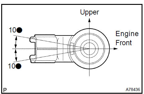
REMOVE ENGINE MOVING CONTROL ROD W/BRACKET
a. Remove the 3 bolts and the engine moving control rod w/ bracket.
-
REMOVE ENGINE MOUNTING STAY No.2 RH
-
REMOVE ENGINE MOUNTING BRACKET No.2 RH
-
REMOVE FAN AND GENERATOR V BELT
-
DISCONNECT OIL RESERVOIR TO PUMP HOSE No.1
22. DISCONNECT RETURN TUBE SUB−ASSY
-
DISCONNECT UNION TO CONNECTOR TUBE HOSE
-
DISCONNECT FLOOR SHIFT CABLE TRANSMISSION CONTROL SHIFT (A/T)
-
DISCONNECT FLOOR SHIFT CABLE TRANSMISSION CONTROL SHIFT (M/T)
-
DISCONNECT FLOOR SHIFT CABLE TRANSMISSION CONTROL SELECT (M/T)
-
REMOVE CLUTCH RELEASE CYLINDER ASSY (M/T)
-
Remove the bolt and flexible hose.
-
Remove the 2 bolts and clutch release cylinder.
-
DISCONNECT HEATER INLET WATER HOSE
-
DISCONNECT HEATER OUTLET WATER HOSE
-
DISCONNECT FUEL TUBE SUB−ASSY
-
DISCONNECT ENGINE WIRE
-
Disconnect the engine wire from the ECM and J/B.
-
Disconnect the engine wire from the engine room J/B.
-
Remove the nut fixing the wire harness.
-
Using a screwdriver, unlock the engine room J/B.
Disconnect the engine wire by pulling it upward.
3. Disconnect the connectors.
c. Pull out the engine wire.
-
Disconnect the B terminal of the generator.
-
Remove the body ground.
-
Remove the starter connector.
32. DISCONNECT ENGINE WIRE No.2
a. Remove the nut and disconnect terminal 30 of the starter.
 Disconnect engine wire No.2
-
REMOVE GENERATOR ASSY
-
REMOVE COMPRESSOR AND MAGNETIC CLUTCH
HINT: Hang up the hoses instead of detaching.
-
REMOVE EXHAUST PIPE ASSY FRONT
-
REMOVE FRONT STABILIZER LINK ASSY LH
-
Using a 6 mm socket hexagon wrench, fix the stud bolt.
-
Remove the nut and disconnect the stabilizer link.
37. REMOVE FRONT STABILIZER LINK ASSY RH
HINT: Use the same procedures described for the LH side.
38. REMOVE FRONT AXLE HUB LH NUT
a. Using SST and a hammer, strike the lock nut covering to remove it.
SST 09930−00010
NOTICE:
-
Set the drive shaft’s groove so that it faces up. Then use the SST and hammer.
-
Remove the covering from the lock nut completely or the screw of the drive shaft may be damaged.
-
Do not sharpen the tip of the SST.
b. Using a 30 mm socket wrench, remove the lock nut.
Remove front axle hub LH nut
39. REMOVE FRONT AXLE HUB RH NUT
HINT: Use the same procedures described for the LH side.
40. REMOVE SPEED FRONT LH (W/ ABS)
a. Remove the bolt and disconnect the speed from the steering knuckle.
NOTICE: Keep the speed tip and connection free from foreign matter.
41. REMOVE SPEED FRONT RH (W/ ABS)
HINT: Use the same procedures described for the LH side.
42. DISCONNECT TIE ROD ASSY LH
-
Remove the cotter pin and castle nut.
-
Using SST, disconnect the tie rod end from the steering knuckle.
SST 09628−62011
NOTICE: Be careful not to damage the cover of the ball joint.
Remove speed front RH (W/ abs)
43. DISCONNECT TIE ROD ASSY RH
HINT: Use the same procedures described for the LH side.
44. DISCONNECT FRONT SUSPENSION ARM SUB−ASSY LOWER No.1 LH
-
Remove the bolt and 2 nuts, as shown in the illustration.
-
Using a plastic hammer, disconnect the drive shaft from the axle hub.
 Disconnect front suspension arm sub-assy lower No.1 LH
45. DISCONNECT FRONT SUSPENSION ARM SUB−ASSY LOWER No.1 RH
HINT: Use the same procedures described for the LH side.
46. REMOVE DRIVE PLATE & TORQUE CONVERTER CLUTCH SETTING BOLT
a. Fix the crankshaft and remove the 6 setting bolts.
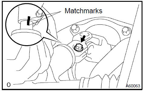
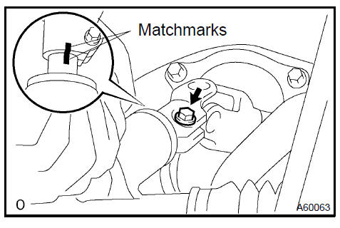
47. REMOVE STEERING INTERMEDIATE SHAFT ASSY
a. Loosen the sliding yoke bolt.
-
Place matchmarks on the intermediate shaft and control valve shaft.
-
Remove the bolt and the steering intermediate shaft.
d. To prevent the steering wheel from rotating, fix the wheel with the seat belt.
NOTICE: If the steering wheel is not fixed, the spiral cable will be damaged.
48. REMOVE ENGINE ASSEMBLY WITH TRANSAXLE
-
Set the engine lifter.
-
Remove the 4 bolts, 2 nuts and frame side rail plate RH and LH.
-
Remove the 4 bolts, 2 nuts and front suspension member brace rear RH and LH.
-
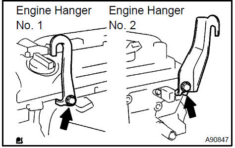
Carefully remove the engine assembly from the vehicle.
e. Install the 2 engine hangers as shown in the illustration.
Parts No.:
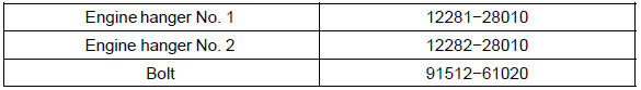
Torque: 38 N·m (387 kgf·cm, 28 ft lbf)
f. Using a chain block and an engine sling device, hang the engine assembly.
49. REMOVE VANE PUMP ASSY
-
Disconnect the PS oil pressure switch connector.
-
Remove the 2 bolts and vane pump from the engine.
 Remove vane pump assy
50. REMOVE FRONT FRAME ASSY
a. A/T: Remove the nut installing the engine mounting insulator LH.
b. M/T: Remove the bolt installing the engine mounting insulator LH.
c. Remove the nut installing the engine mounting insulator RH.
d. Remove the bolt installing the engine mounting insulator FR.
e. M/T: Remove the bolt installing the engine lateral control rod.
f. Raise the engine assembly and separate the front frame.
-
REMOVE FRONT DRIVE SHAFT ASSY LH
-
REMOVE FRONT DRIVE SHAFT ASSY RH
-
REMOVE STARTER ASSY
-
SEPARATE AUTOMATIC TRANSAXLE ASSY (A/T)
-
SEPARATE MANUAL TRANSAXLE ASSY (M/T)
-
REMOVE DRIVE PLATE & RING GEAR SUB−ASSY
(A/T)
a. TMC made: Using SST, fix the crankshaft.
SST 09213−54015 (91651−60855), 09330−00021
b. TMMK made: Using SST, fix the crankshaft.
SST 09960−10010 (09962−01000, 09963−01000)
c. Remove the 8 bolts, rear spacer, drive plate and front spacer.
-
REMOVE CLUTCH COVER ASSY (M/T)
-
REMOVE CLUTCH DISC ASSY (M/T)
-
REMOVE FLYWHEEL SUB−ASSY (M/T)
a. Using SST, fix the crankshaft.
SST 09213−54015 (91651−60855), 09330−00021
b. Remove the 8 bolts, rear spacer and flywheel.
-
INSTALL ENGINE STAND
-
REMOVE INTAKE MANIFOLD
a. Remove the 5 bolts, 2 nuts, intake manifold and gasket.
62. INSPECT INTAKE MANIFOLD
a. Using a precision straight edge and feeler gauge, measure the surface contacting the cylinder head for warpage.
Maximum warpage: 0.20 mm (0.0079 in.)
If the warpage is greater than maximum, replace the manifold.
Inspect intake manifold
-
REMOVE INTAKE MANIFOLD RUNNER VALVE ASSY (PZEV only)
-
REMOVE VENTILATION HOSE
-
REMOVE VENTILATION HOSE No.2
-
REMOVE ENGINE WIRE
-
REMOVE INTAKE MANIFOLD INSULATOR No.1
-
REMOVE OIL LEVEL GAGE SUB−ASSY
-
REMOVE OIL LEVEL GAGE GUIDE
-
REMOVE MANIFOLD CONVERTER INSULATOR No.1
-
REMOVE EXHAUST MANIFOLD CONVERTER SUB−ASSY
a. Remove the 3 bolts, 2 nuts, and the No. 1 and No. 2 exhaust manifold stays.
b. Remove the 5 nuts, exhaust manifold converter and gasket.
72. INSPECT CONVERTER SUB−ASSY, EXHAUST MANIFOLD
a. Using a precision straight edge and feeler gauge, measure the surface contacting the cylinder head for warpage.
Maximum warpage: 0.70 mm (0.0276 in.)
If the warpage is greater than the maximum, replace the manifold.
 Inspect converter sub-assy, exhaust manifold
-
REMOVE WATER INLET
-
REMOVE THERMOSTAT
-
REMOVE IGNITION COIL ASSY
-
REMOVE V−RIBBED BELT TENSIONER ASSY
a. Remove the bolt, nut and belt tensioner.
Remove V-ribbed belt tensioner assy
-
REMOVE DRIVE SHAFT BEARING BRACKET
-
REMOVE ENGINE MOUNTING BRACKET RH
-
REMOVE FUEL DELIVERY PIPE W/INJECTOR
-
REMOVE WATER BY−PASS PIPE No.1
-
REMOVE ENGINE OIL PRESSURE SWITCH ASSY
a. Remove the oil pressure switch.
 Remove engine oil pressure switch assy
82. REMOVE KNOCK
-
Disconnect the connector.
-
Remove the nut and .
-
REMOVE ENGINE COOLANT TEMPERATURE
-
REPLACE PARTIAL ENGINE ASSY
-
INSTALL ENGINE COOLANT TEMPERATURE
-
Install a new gasket to the .
-
Install the .
Torque: 20 N·m (204 kgf·cm, 15 ft·lbf)
86. INSTALL KNOCK
a. Install the with the nut, as shown in the illustration.
Torque: 20 N·m (204 kgf·cm, 15 ft·lbf)
Install knock
87. INSTALL ENGINE OIL PRESSURE SWITCH ASSY
-
Clean the threads of the oil pressure switch. Apply adhesive to 2 or 3 threads of the oil.
Adhesive: Part No. 08833−00080 THREE BOND 1344 or equivalent
-
Install the oil pressure switch.
Torque: 15 N·m (153 kgf·cm, 11 ft·lbf)
88. INSTALL WATER BY−PASS PIPE No.1
a. Install a new gasket and the by−pass pipe with the bolt and 2 nuts.
Torque: 9.0 N·m (92 kgf·cm, 80 in.·lbf)
-
INSTALL FUEL DELIVERY PIPE W/INJECTOR
-
INSTALL ENGINE MOUNTING BRACKET RH Torque: 54 N·m (551 kgf·cm, 40 ft·lbf)
-
INSTALL DRIVE SHAFT BEARING BRACKET Torque: 64 N·m (653 kgf·cm, 47 ft·lbf)
-
INSTALL V−RIBBED BELT TENSIONER ASSY
a. Install the belt tensioner with the bolt and the nut.
Torque: 59.5 N·m (607 kgf·cm, 44 ft·lbf)
Install v-ribbed belt tensioner assy
-
INSTALL IGNITION COIL ASSY Torque: 9.0 N·m (92 kgf·cm, 80 in.·lbf)
-
INSTALL THERMOSTAT
-
INSTALL WATER INLET Torque: 9.0 N·m (92 kgf·cm, 80 in.·lbf)
-
INSTALL EXHAUST MANIFOLD CONVERTER SUB−ASSY
a. Install a new gasket and the exhaust manifold converter.
Uniformly tighten the 5 nuts in the sequence shown in the illustration.
Torque: 37 N·m (378 kgf·cm, 27 ft·lbf)
b. Install the No. 1 and No. 2 exhaust manifold stays with the 3 bolts and 2 nuts.
Torque: 44 N·m (449 kgf·cm, 32 ft·lbf)
-
INSTALL MANIFOLD CONVERTER INSULATOR No.1 Torque: 12 N·m (122 kgf·cm, 9 ft·lbf)
-
INSTALL OIL LEVEL GAGE GUIDE
-
Apply a light coat of engine oil to the O−ring and install it to the guide.
-
Install the oil level gage and guide with the bolt.
Torque: 9.0 N·m (92 kgf·cm, 80 in.·lbf)
-
INSTALL INTAKE MANIFOLD RUNNER VALVE ASSY (PZEV only)
-
INSTALL INTAKE MANIFOLD
a. Install a new gasket and the intake manifold with the 5 bolts and 2 nuts.
Torque: 30 N·m (306 kgf·cm, 22 ft·lbf)
101. INSTALL DRIVE PLATE & RING GEAR SUB−ASSY (A/T)
a. TMC made: Using SST, fix the crankshaft.
SST 09213−54015 (91651−60855), 09330−00021
b. TMMK made: Using SST, fix the crankshaft.
SST 09960−10010 (09962−01000, 09963−01000)
-
Clean the bolt and the bolt hole.
-
Apply adhesive to 2 or 3 threads of the bolt end. Adhesive: Part No. 08833−00070, THREE BOND or equivalent.
-
Install the front spacer, drive plate and rear spacer with 8 bolts. Uniformly tighten the 8 bolts in the sequence shown in the illustration.
Torque: 98 N·m (1,000 kgf·cm, 72 ft·lbf)
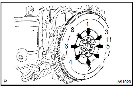
102. INSTALL FLYWHEEL SUB−ASSY
a. Using SST, fix the crankshaft.
SST 09213−54015 (91651−60855), 09330−00021
-
Clean the bolt and the bolt hole.
-
Apply adhesive to 2 or 3 threads of the bolt end.
Adhesive: Part No. 08833−00070, THREE BOND or equivalent.
-
Install the flywheel. Uniformly tighten the 8 bolts in the sequence shown in the illustration.
Torque: 130 N·m (1,330 kgf·cm, 96 ft·lbf)
-
INSTALL CLUTCH DISC ASSY (M/T)
-
INSTALL CLUTCH COVER ASSY (M/T)
-
INSTALL AUTOMATIC TRANSAXLE ASSY (A/T)
-
INSTALL MANUAL TRANSAXLE ASSY (M/T)
-
INSTALL STARTER ASSY Torque: 39 N·m (398 kgf·cm, 29 ft·lbf)
-
INSTALL FRONT DRIVE SHAFT ASSY RH
-
INSTALL FRONT DRIVE SHAFT ASSY LH
-
INSTALL FRONT FRAME ASSY
a. A/T: Install the engine mounting insulator LH with the nut.
Torque: 95 N·m (969 kgf·cm, 70 ft·lbf)
b. M/T: Install the engine mounting insulator LH with the bolt.
Torque: 143 N·m (1,459 kgf·cm, 105 ft·lbf)
c. Install the engine mounting insulator RH with the nut.
Torque: 95 N·m (969 kgf·cm, 70 ft·lbf)

d. Install the engine mounting insulator FR with the bolt.
Torque: 87 N·m (888 kgf·cm, 64 ft·lbf)
e. M/T: Install the engine lateral control rod with the bolt.
Torque: 89 N·m (910 kgf·cm, 66 ft·lbf)
111. INSTALL VANE PUMP ASSY
-
Install the vane pump to the engine with the 2 bolts.
-
Connect the PS oil pressure switch connector.
Torque: 43 N·m (439 kgf·cm, 32 ft·lbf)
Install vane pump assy
112. INSTALL ENGINE ASSEMBLY WITH TRANSAXLE
-
Set the engine assembly with transaxle on the engine lifter.
-
Install the engine assembly to the vehicle.
-
Install the frame side plate LH and RH with the 4 bolts and 2 nuts.
Torque:
85 N·m (867 kgf·cm, 63 ft·lbf) for bolt A 32 N·m (326 kgf·cm, 24 ft·lbf) for bolt B and nut
d. Install the front suspension member brace rear RH and LH with the 4 bolts and 2 nuts.
Torque:
85 N·m (867 kgf·cm, 63 ft·lbf) for bolt C
32 N·m (326 kgf·cm, 24 ft·lbf) for bolt D and nut
113. INSTALL STEERING INTERMEDIATE SHAFT ASSY
a. Align the matchmarks on the intermediate shaft and control valve shaft.
Torque: 35 N·m (357 kgf·cm, 26 ft·lbf)
b. Tighten the bolt.
Torque: 35 N·m (357 kgf·cm, 26 ft·lbf)
114. INSTALL DRIVE PLATE & TORQUE CONVERTER CLUTCH SETTING BOLT (A/T)
a. Fix the crankshaft, and install the 6 setting bolts.
Torque: 41 N·m (418 kgf·cm, 30 ft·lbf)
Install drive plate & torque converter clutch setting bolt (A/T)
115. INSTALL FRONT SUSPENSION ARM SUB−ASSY LOWER No.1 LH
-
Install the drive shaft to the steering knuckle.
-
Install the suspension lower arm with the bolt and the 2 nuts. Torque: 75 N·m (765 kgf·cm, 55 ft·lbf)
Install front suspension arm sub-assy lower No.1 LH
116. INSTALL FRONT SUSPENSION ARM SUB−ASSY LOWER No.1 RH
HINT: Use the same procedures described for the LH side.
117. INSTALL TIE ROD ASSY LH
a. Connect the tie rod end to the steering knuckle and install a new castle nut.
Torque: 49 N·m (500 kgf·cm, 36 ft·lbf)
NOTICE:
-
Prevent any lubricant from contacting the thread and the taper portions.
-
fter tightening the castle nut, tighten it to the additional direction within 60 to put into a cotter pin.
b. Insert a new cotter pin.
118. INSTALL TIE ROD ASSY RH
HINT: Use the same procedures described for the LH side.
-
INSTALL SPEED FRONT LH (W/ABS) Torque: 8.0 N·m (82 kgf·cm, 71 in.·lbf)
-
INSTALL SPEED FRONT RH (W/ABS) Torque: 8.0 N·m (82 kgf·cm, 71 in.·lbf)
-
INSTALL FRONT AXLE HUB LH NUT
-
Using a 30 mm socket wrench, install a new hub nut.
Torque: 294 N·m (3,000 kgf·cm, 217 ft·lbf)
-
Using a chisel and hammer, tapped the front axle hub LH nut.
Install front axle hub LH nut
122. INSTALL FRONT AXLE HUB RH NUT
HINT: Use the same procedures described for the LH side.
123. INSTALL FRONT STABILIZER LINK ASSY LH
a. Using a 5 mm socket hexagon wrench, fix the stud bolt and install the nut.
Torque: 74 N·m (755 kgf·cm, 55 ft·lbf)
124. INSTALL FRONT STABILIZER LINK ASSY RH
HINT: Use the same procedures described for the LH side.
-
INSTALL EXHAUST PIPE ASSY FRONT
-
CONNECT FUEL TUBE SUB−ASSY
-
INSTALL RETURN TUBE SUB−ASSY

128. INSTALL OIL RESERVOIR TO PUMP HOSE No.1
-
INSTALL COMPRESSOR AND MAGNETIC CLUTCH
-
INSTALL GENERATOR ASSY
-
INSTALL FAN AND GENERATOR V BELT
-
CONNECT ENGINE WIRE No.2
-
CONNECT ENGINE WIRE
-
INSTALL ENGINE MOUNTING BRACKET No.2 RH Torque: 52 N·m (531 kgf·cm, 38 ft·lbf)
-
INSTALL ENGINE MOUNTING STAY No.2 RH Torque: 64 N·m (653 kgf·cm, 47 ft·lbf)
-
INSTALL ENGINE MOVING CONTROL ROD W/BRACKET
a. Install the engine mounting control rod with the 3 bolts.
Torque: 64 N·m (653 kgf·cm, 47 ft·lbf)
Install engine moving control rod W/bracket
-
INSTALL AIR CLEANER ASSY Torque: 5.0 N·m (51 kgf·cm, 44 in.·lbf)
-
ADD AUTOMATIC TRANSAXLE FLUID (A/T)
-
ADD MANUAL TRANSAXLE OIL (M/T)
-
ADD ENGINE OIL
-
ADD ENGINE COOLANT
-
ADD POWER STEERING FLUID
-
BLEED POWER STEERING FLUID
-
CHECK FOR OIL LEAKS
-
CHECK FOR ENGINE COOLANT LEAKS
-
CHECK FOR FUEL LEAKS
-
INSTALL FRONT WHEEL
-
ADJUST FRONT WHEEL ALIGNMENT
-
INSPECT CHECK IDLE SPEED AND IGNITION TIMING
-
INSPECT CO/HC
-
CHECK ABS SPEED SIGNAL (W/ ABS)
OVERHAUL
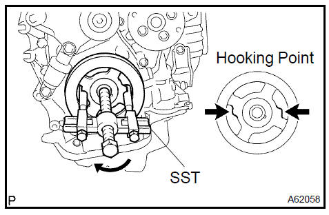
1. REMOVE OIL FILTER SUB−ASSY
a. Using SST, remove the oil filter.
SST 09228−06501
Remove oil filter sub-assy
2. REMOVE OIL FILTER UNION
a. Using a 12 mm hexagon wrench, remove the union.
-
REMOVE OIL FILLER CAP SUB−ASSY
-
REMOVE VENTILATION VALVE SUB−ASSY
-
REMOVE SPARK PLUG
-
REMOVE CYLINDER HEAD COVER SUB−ASSY
a. Remove the 8 bolts, 2 nuts, and cylinder head cover.
Remove cylinder head cover sub-assy
-
REMOVE CYLINDER HEAD COVER GASKET
-
REMOVE CRANKSHAFT POSITION
-
REMOVE CRANKSHAFT PULLEY
-
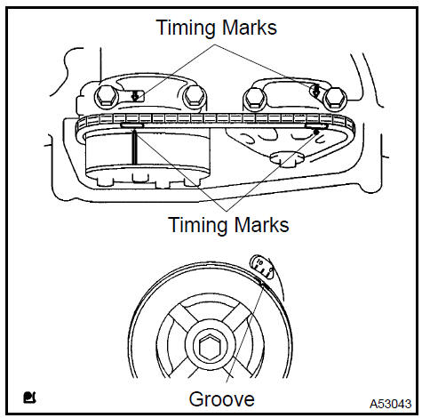
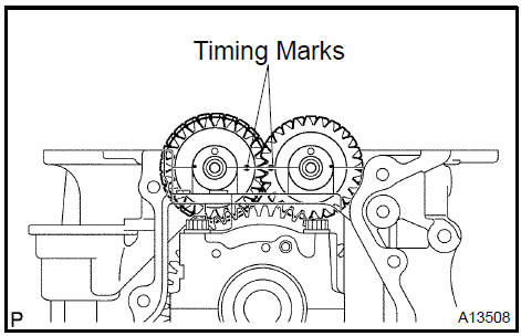
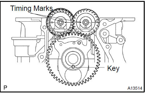
Turn the crankshaft pulley and align its groove with timing mark 0 of the timing chain cover.
-
Check that the timing marks of the camshaft timing sprockets are aligned with the timing marks of the No. 1 bearing cap, as shown in the illustration.
c. TMC made: Remove the crankshaft pulley.
1. Using SST, fix the pulley and loosen the bolt.
SST 09213−54015 (91651−60855), 09330−00021
2. Using SST, remove the bolt and pulley.
SST 09950−50013 (09951−05010, 09952−05010, 09953−05020, 09954−05021)
d TMMK made: Remove the crankshaft pulley.
1. Using SST, fix the crankshaft pulley and loosen a pulley set bolt.
SST 09960−10010 (09962−01000, 09963−01000)
2. Using SST, remove the crankshaft pulley.
SST 09950−40011 (09951−04010, 09952−04010, 09953−04030, 09954−04010, 09955−04041, 09957−04010, 91111−51014)
10. REMOVE CHAIN TENSIONER ASSY No.1
a. Remove the 2 nuts, chain tensioner and gasket.
NOTICE: Do not to turn the crankshaft without the chain tensioner.
Remove chain tensioner assy No.1
11. REMOVE WATER PUMP PULLEY
a. Using SST, remove the water pump pulley.
SST 09960−10010 (09962−01000, 09963−00700)
Remove water pump pulley
12. REMOVE WATER PUMP ASSY
a. Remove the 4 bolts, 2 nuts, bracket and water pump.
Remove water pump assy
-
REMOVE OIL PAN DRAIN PLUG
-
REMOVE OIL PAN SUB−ASSY
a. Remove the 12 bolts and 2 nuts.
b. Insert the blade of SST between the crankcase and oil pan. Cut off applied sealer and remove the oil pan.
SST 09032−00100
NOTICE: Be careful not to damage the contact surface of the cylinder block and oil pan.
15. REMOVE TIMING CHAIN OR BELT COVER SUB−ASSY
-
Remove the 14 bolts and 2 nuts.
-
Remove the timing chain cover by prying between the timing chain cover and cylinder head or cylinder block with a screwdriver.
NOTICE: Be careful not to damage the contact surfaces of the timing chain cover, cylinder block and cylinder head.
Remove timing chain or belt cover sub-assy
16. REMOVE TIMING GEAR CASE OR TIMING CHAIN CASE OIL SEAL
a. Using a screwdriver and a hammer, remove the oil seal.
Remove timing gear case or timing chain case oil seal
-
REMOVE CRANKSHAFT POSITION PLATE No.1
-
REMOVE TIMING CHAIN GUIDE
-
REMOVE CHAIN TENSIONER SLIPPER
-
REMOVE CHAIN VIBRATION DAMPER No.1
-
REMOVE CHAIN SUB−ASSY
-
REMOVE CRANKSHAFT TIMING GEAR OR SPROCKET
-
REMOVE No.2 CHAIN SUB−ASSY
a) Turn the crankshaft counterclockwise by 90 , and align the adjusting hole of the oil pump driven sprocket with the groove of the oil pump.
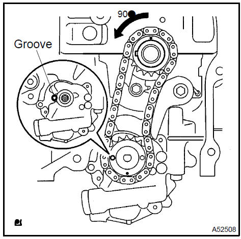
b. Put a bar (ϕ 4 mm) in the adjusting hole of the oil pump driven sprocket to temporarily lock the sprocket in position.
Remove the nut.
-
Remove the bolt, chain tensioner plate and spring.
-
Remove the oil pump drive sprocket, oil pump driven sprocket and chain.
24. REMOVE OIL PUMP ASSY
a. Remove the 3 bolts, oil pump and gasket.
25. REMOVE No.2 CAMSHAFT
-
Uniformly loosen and remove the No. 2 camshaft’s 10 bearing cap bolts in the sequence shown in the illustration.
Then remove the 5 bearings.
-
Remove the camshaft.
 Remove No.2 Camshaft
26. REMOVE CAMSHAFT
-
Uniformly loosen and remove the No. 2 camshaft’s 10 bearing cap bolts in the sequence shown in the illustration.
Then remove the 5 bearings.
-
Remove the camshaft.
 Remove camshaft
-
REMOVE CAMSHAFT BEARING No.1
-
REMOVE CAMSHAFT TIMING GEAR OR SPROCKET
a. Fix the camshaft with a vise and remove the camshaft timing sprocket.
NOTICE: Be careful not to damage the camshaft.
 Remove camshaft timing gear or sprocket
29. REMOVE CAMSHAFT TIMING GEAR ASSY
-
Fix the camshaft with a vise, and make sure that the camshaft timing gear does not move.
-
Cover all the oil ports with vinyl tape except the advanced angle side, as shown in the illustration.
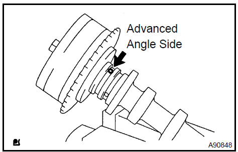
c. Using an air gun, apply about 150 kPA (1.5 kgf/cm, 21 psi) of air pressure to the port on the advanced angle side.
CAUTION: Some oil spraying will occur. Contain the spray with a shop rag.
HINT: This operation releases the lock pin for the extreme retarded angle lock.
d. Under the condition above, check that the camshaft timing gear can be turned by hand to the advanced angle side (counterclockwise), the direction of the arrow in the illustration.
Standard: Must turn
HINT: The camshaft timing gear will turn to the advanced angle side without applying force by hand depending on the force of the air pressure applied. Also, if applying pressure to the oil path is difficult as a result of air leakage from the port, the lock−pin may be difficult to release.
e. Remove the fringe bolt from the camshaft timing gear.
NOTICE:
-
Be sure not to remove the other 4 bolts.
-
If planning to reuse the camshaft timing gear, release the straight pin lock first, and then install the gear.
-
REMOVE CAMSHAFT BEARING No.2
-
REMOVE CAMSHAFT TIMING OIL CONTROL VALVE ASSY
-
REMOVE CYLINDER HEAD SUB−ASSY
a. Using a 10 mm bi−hexagon wrench, uniformly loosen the 10 bolts in the sequence shown in the illustration. Remove the 10 cylinder head bolts and plate washers.
NOTICE:
-
Be careful not to drop washers into the cylinder head.
-
Head warpage or cracking could
-
REMOVE CYLINDER HEAD GASKET
-
REMOVE CYLINDER BLOCK WATER DRAIN COCK SUB−ASSY
-
REMOVE OIL CONTROL VALVE FILTER
a. Using a 6 mm socket hexagon wrench, remove the plug and filter.
-
REMOVE W/HEAD TAPER SCREW PLUG No.1
-
INSPECT BALANCESHAFT THRUST CLEARANCE
a. Using a dial indicator, measure the thrust clearance while moving the balance shaft back and forth.
Specified thrust clearance: 0.050 to 0.090 mm (0.0020 to 0.0035 in.)
If the thrust clearance is greater than the maximum, replace the balance shaft housing and bearings. If necessary, replace the balance shaft.
 Inspect balanceshaft thrust clearance
38. INSPECT BALANCESHAFT OIL CLEARANCE
a. Uniformly loosen and remove the 8 bolts in the sequence shown in the illustration.
NOTICE: Be careful not to damage the contact surfaces of the balance shaft housing and crankcase.
HINT: Keep the lower bearing and balance shaft housing together.
b. Lift out the No. 1 and No. 2 balance shafts.
HINT: Keep the upper bearing with the crankcase.
-
Clean each bearing and journal.
-
Check each bearing and journal for pitting and scratches.
If a bearing or journal is damaged, replace the bearings. If necessary, replace the balance shaft.
e. Place the No. 1 and No. 2 balance shafts on the crankcase.
-
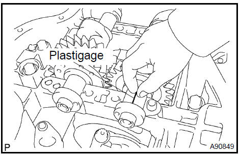
Lay a strip of Plastigage across each journal, and install the balance shaft housing.
-
Apply light coat of engine oil on the threads and under the heads of the balance shaft housing bolts.
h. Uniformly tighten the 8 bolts in the sequence shown in the illustration.
Torque: 22 N·m (220 kgf·cm, 16 ft·lbf)
HINT: The balance shaft housing bolts are tightened in 2 progressive steps.
-
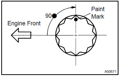
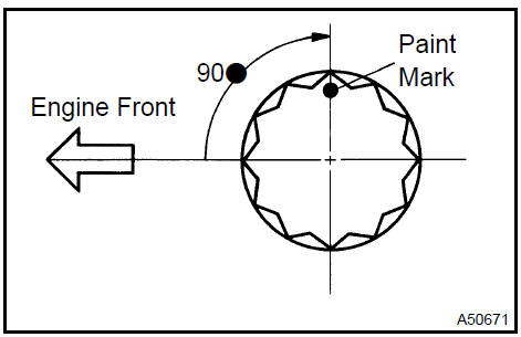
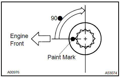
Mark the front side of each balance shaft housing bolt head with paint.
-
Retighten the bolts by 90 as shown in the illustration.
-
Check that the paint marks are now at a 90 angle to the front.
l. Remove the balance shaft housing, and measure the Plastigage at its widest point.
Specified oil clearance: 0.004 to 0.031 mm (0.0002 to 0.0012 in.)
m. Completely remove the plastigage after the inspection.
If the clearance is greater than the maximum, replace the bearing.
If necessary, replace the balance shaft.
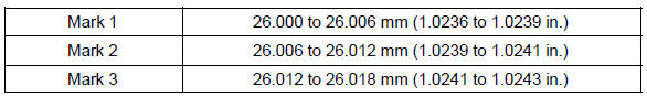
HINT: If replacing a bearing, replace it with one that has the same number as the stiffening crankcase. There are 3 sizes of standard bearings: 1, 2 and 3.
Balance shaft housing journal bore diameter:
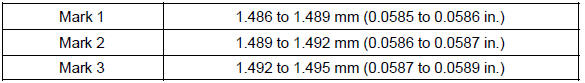
Balance shaft journal diameter: 22.985 to 23.000 mm (0.9049 to 0.9055 in.) Standard bearing center wall thickness:
n. Completely remove the Plastigage after the inspection.
-
REMOVE BALANCESHAFT
-
REMOVE BALANCESHAFT BEARING No. 1
-
REMOVE ENGINE REAR OIL SEAL
-
Using a knife, cut off the oil seal lip.
-
Using a screwdriver with its tip taped, pry out the oil seal.
NOTICE: After the removal, check the crankshaft for damage. If it is damaged, smooth the surface with 400−grit sandpaper.
 Remove engine rear oil seal
42. REMOVE STIFFENING CRANKCASE ASSY
-
Uniformly loosen and remove the 11 bolts in the sequence shown in the illustration.
-
Using a screwdriver, remove the crankcase by prying the portions between the crankcase and cylinder block.
NOTICE: Be careful not to damage the contact surfaces of the crankcase and cylinder block.
c. Remove the O−ring from the cylinder block.
 Remove stiffening crankcase assy
43. INSPECT OIL PUMP DRIVE SPROCKET
-
Wrap the chain around the drive sprocket.
-
Using a vernier caliper, measure the drive sprocket diameter with the chain.
NOTICE:
The vernier caliper must contact the chain rollers for the measurement.
Minimum sprocket diameter (w/ chain): 48.2 mm (1.898 in.)
If the diameter is less than the minimum, replace the chain and sprocket.
 Inspect oil pump drive sprocket
44. INSPECT OIL PUMP DRIVEN SPROCKET
-
Wrap the chain around the driven sprocket.
-
Using a vernier caliper, measure the driven sprocket diameter with the chain.
NOTICE: The vernier caliper must contact the chain rollers for the measurement.
Minimum sprocket diameter (w/ chain): 48.2 mm (1.898 in.)
If the diameter is less than the minimum, replace the chain and drive shaft gear.
 Inspect oil pump driven sprocket
45. INSPECT CRANKSHAFT TIMING GEAR OR SPROCKET
-
Wrap the chain around the timing sprocket.
-
Using a vernier caliper, measure the timing sprocket diameter with the chain.
NOTICE: The vernier caliper must contact the chain rollers for the measurement.
Minimum sprocket diameter (w/ chain): 51.6 mm (2.031 in.)
If the diameter is less than the minimum, replace the chain and timing gear.
 Inspect crankshaft timing gear or sprocket
46. INSPECT CHAIN TENSIONER SLIPPER
a. Measure the tensioner slipper wear.
Maximum wear: 1.0 mm (0.039 in.)
If the wear is greater than the maximum, replace the tensioner slipper.
 Inspect chain tensioner slipper
47. INSPECT CHAIN VIBRATION DAMPER No.1
a. Measure the vibration damper wear.
Maximum wear: 1.0 mm (0.039 in.)
If the wear is greater than the maximum, replace the vibration damper.
 Inspect chain vibration damper No.1
48. INSPECT CYLINDER HEAD SET BOLT
a. Using a vernier caliper, measure the length of the head bolts from the seat to the end.
Specified bolt length: 161.3 to 164.2 mm (6.350 to 6.465 in.)
If the length is greater than the maximum, replace the bolt.
 Inspect cylinder head set bolt
49. INSPECT CHAIN TENSIONER ASSY No.1
-
Check that the plunger moves smoothly when the ratchet pawl is raised.
-
Release the ratchet pawl and check that the plunger is locked in place by the ratchet pawl and does not move when pushed with finger.
 Inspect chain tensioner assy No.1
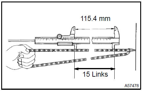
50. INSPECT CHAIN SUB−ASSY
a. Using a vernier caliper, measure the length of 15 links with the chain fully stretched.
Maximum chain elongation: 115.4 mm (4.543 in.)
If the elongation is greater than the maximum, replace the chain.
NOTICE: Make the same measurements pulling at 3 or more places selected at random. Average the measurements.
 Inspect chain sub-assy
51. INSPECT CAMSHAFT TIMING GEAR OR SPROCKET
-
Wrap the chain around the timing sprocket.
-
Using a vernier caliper, measure the timing sprocket diameter with the chain.
Minimum sprocket diameter (w/chain): 97.3 mm (3.831 in.)
NOTICE: The vernier caliper must contact the chain rollers for the measurement.
If the diameter is less than the minimum, replace the chain and timing gear.
 Inspect camshaft timing gear or sprocket
52. INSPECT CAMSHAFT
a. Check the camshaft for runout.
-
Place the camshaft on V−blocks.
-
Using a dial indicator, measure the circle runout at the center journal.
Maximum circle runout: 0.03 mm (0.0012 in.)
If the circle runout is greater than the maximum, replace the camshaft.

b. Using a micrometer, measure the cam lobe height.
Specified cam lobe height: 46.599 to 46.809 mm (1.8346 to 1.8429 in.)
If the cam lobe height is less than the minimum, replace the camshaft.
c. Using a micrometer, measure the journal diameter.
No. 1 journal diameter: 35.971 to 35.985 mm (1.4162 to 1.4167 in.) Other journal diameter: 22.959 to 22.975 mm (0.9039 to 0.9045 in.)
If the journal diameter is not as specified, check the oil clearance.
53. INSPECT No.2 CAMSHAFT
a. Check the camshaft for runout.
1. Place the camshaft on V−blocks.
Using a dial indicator, measure the circle runout at the center journal.
Maximum circle runout: 0.03 mm (0.0012 in.)
If the circle runout is greater than the maximum, replace the camshaft.
b. Using a micrometer, measure the cam lobe height.
Specified cam lobe height: 45.599 to 46.809 mm (1.8346 to 1.8429 in.)
If the cam lobe height is less than the minimum, replace the camshaft.
c. Using a micrometer, measure the journal diameter.
No. 1 journal diameter: 35.971 to 35.985 mm (1.4162 to 1.4167 in.) Other journal diameter: 22.959 to 22.975 mm (0.9039 to 0.9045 in.)
If the journal diameter is not as specified, check the oil clearance.
54. INSTALL BALANCESHAFT BEARING No.1
-
Install the bearings in the crankcase and balance shaft housing.
-
Apply a light coat of engine oil on the bearings.
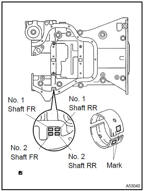
55. INSTALL BALANCESHAFT No. 1 AND No. 2
-
Rotate the driven gear No. 1 of balance shaft No. 1 for the rotating direction until it hits the stopper.
-
Confirm that the matchmarks on driven gear No. 1 and No. 2 are matched.
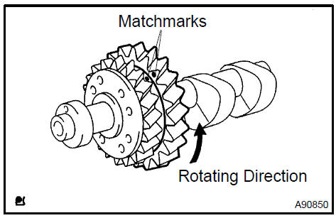
-
Align the timing marks of the No. 1 and No. 2 balance shafts as shown in the illustration.
-
Place the No. 1 and No. 2 balance shafts on the crank case.
-
Apply a light coat of engine oil under the heads of the balance shaft housing bolts.
f. Uniformly tighten the 8 bolts in the sequence shown in the illustration.
Torque: 22 N·m (220 kgf·cm, 16 ft·lbf)
HINT: The balance shaft housing bolts are tightened in 2 progressive steps.
-
Mark the front side of each balance shaft housing bolt head with paint.
-
Retighten the bolts by 90 as shown in the illustration.
-
Check that the painted marks are now at a 90 angle to the front.
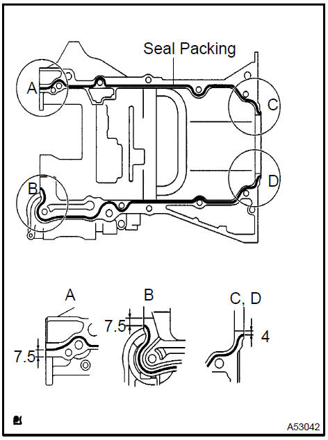
56. INSTALL STIFFENING CRANKCASE ASSY
a. Apply seal packing in a continuous bead (diameter: 2.5 to 3 mm (0.098 to 0.118 in.)) to the places shown in the illustration.
Seal packing: Part No. 08826−00080 or equivalent
NOTICE:
-
Remove any oil from the contact surface.
-
Install the crankcase within 3 minutes after applying seal packing.
-
Do not start the engine for at least 2 hours after installing.
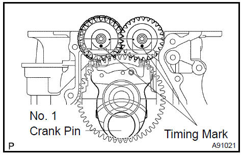
b. Place a new O−ring on the cylinder block, as shown in the illustration.
c. With the No. 1 crank pin of the crankshaft placed at 6 o’clock, install the No. 1 and No. 2 balanceshaft and the adjusting hole as shown in the illustration.
d. Uniformly tighten the 11 bolts in the sequence shown in the illustration.
Torque: 33 N·m (332 kgf·cm, 24 ft·lbf
e. Confirm that the timing marks of the balanceshafts are matched when the key groove is placed at 6 o’clock, as shown in the illustration.
57. INSTALL ENGINE REAR OIL SEAL
a. Apply MP grease to a new oil seal lip.
NOTICE: Keep the lip off the foreign materials.
b. Using SST and a hammer, evenly tap the oil seal until its surface is flush with the rear oil seal retainer edge.
SST 09223−15030, 09950−70010 (09951−07100)
NOTICE: Wipe off extra grease on the crankshaft.
 Install engine rear oil seal
58. INSTALL W/HEAD TAPER SCREW PLUG No.1
a. Apply adhesive to the threads of the plug and install it.
Adhesive: Part No. 08833−00070, THREE BOND 1324 or equivalent Torque: 26 N·m (265 kgf·cm, 19 ft·lbf)
 Install W/head taper screw plug No.1
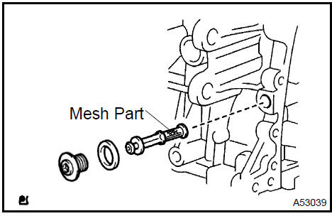
59. INSTALL OIL CONTROL VALVE FILTER
-
Check that no foreign substance is on the mesh part of the filter.
-
Using a 6 mm socket hexagon wrench, install a new gasket and the oil control valve filter with the screw plug.
Torque: 30 N·m (306 kgf·cm, 22 ft·lbf)
 Install oil control valve filter
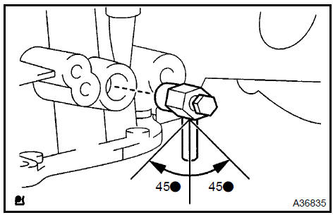
60. INSTALL CYLINDER BLOCK WATER DRAIN COCK SUB−ASSY
a. Install the water drain cock within the range shown in the illustration.
Torque: 25 N·m (255 kgf·cm, 18 ft·lbf)
 Install cylinder block water drain cock sub-assy
61. INSTALL CYLINDER HEAD GASKET
a. Place a new gasket on the cylinder block surface with the Lot No. stamp upward.
NOTICE:
-
Remove any oil from contact surface.
-
Be careful of the installation direction.
-
To avoid damage to the gasket, place the cylinder head on the gasket carefully.
 Install cylinder head gasket
62. INSTALL CYLINDER HEAD SUB−ASSY
HINT: The cylinder head bolts are tightened in 2 progressive steps.
-
Apply a light coat of engine oil on the threads and under the heads of the cylinder head bolts.
-
Install the 10 bolts and plate washers to the cylinder head.
NOTICE: Do not drop the washers into the cylinder head.
c. Using a 10 mm bi−hexagon wrench, uniformly tighten the 10 bolts in the sequence shown in the illustration.
Torque: 79 N·m (806 kgf·cm, 58 ft·lbf)
-
Mark the front side of each cylinder head bolt with paint.
-
Retighten the cylinder head bolts by 90 in the sequence shown in the illustration.
-
Check that the painted marks are now at a 90 angle to the front.
-
INSTALL CAMSHAFT TIMING OIL CONTROL VALVE ASSY Torque: 9.0 N·m (92 kgf·cm, 80 in.·lbf)
-
INSTALL CAMSHAFT BEARING No.2
65. INSTALL CAMSHAFT TIMING GEAR ASSY
-
Put the camshaft timing gear and the camshaft together with the straight pin and key groove.
-
Turn the camshaft timing gear (as shown in the illustration) while pushing it lightly against the camshaft. Push further at the position where the pin enters the groove.
CAUTION: Be sure not to turn the camshaft timing gear to the retarded angle side (to the right angle).
-
Check that there is no clearance between the gear’s fringe and the camshaft.
-
Tighten the fringe bolt with the camshaft timing gear fixed.
Torque: 54 N·m (551 kgf·cm, 40 ft·lbf)
Engine (2AZ−FE) (From July, 2003)
Timing gear case or timing chain case oil seal (2AZ−FE)(From July, 2003)
Engine rear oil seal (2AZ−FE)(From July, 2003)
Cylinder head assy (2AZ−FE) (From July, 2003)
Cylinder block assy (2AZ−FE)(From July, 2003)
Engine (1MZ−FE/3MZ−FE)
Drive belt (1MZ−FE/3MZ−FE)
Valve clearance (1MZ−FE/3MZ−FE)
Partial engine assy (1MZ−FE/3MZ−FE)
Partial engine assy (2AZ−FE)(From July, 2003)
Partial engine assy (1MZ−FE/3MZ−FE)
Timing belt (1MZ−FE/3MZ−FE)
Camshaft (RH BANK) (1MZ−FE/3MZ−FE)
Camshaft (LH BANK) (1MZ−FE/3MZ−FE)
Cylinder head gasket (1MZ−FE/3MZ−FE)
Cylinder head gasket No.2 (1MZ−FE/3MZ−FE)
Oil pump seal (1MZ−FE/3MZ−FE)
Engine rear oil seal (1MZ−FE/3MZ−FE)
Cylinder head assy (1MZ−FE/3MZ−FE)
Cylinder block assy (1MZ−FE/3MZ−FE)
Partial engine assy (2AZ−FE)(From July, 2003)
Drive belt (2AZ−FE)(From July, 2003)
Valve clearance (2AZ−FE)
Chain (2AZ−FE)(From July, 2003)
Camshaft (2AZ−FE)(From July, 2003)
Cylinder head gasket (2AZ−FE)(From July, 2003)
Toyota Camry XV30 (2002–2006) Service Manual
- Introduction
- Audio & visual system
- Automatic transmission / trans
- Brake
- Clutch
- Communication system
- Cooling
- Cruise control
- Drive shaft / propeller shaft
- Emission control
- Engine control system
- Engine hood/door
- Engine mechanical
- Exhaust
- Exterior/interior trim
- Front suspension
- Fuel
- Heater & air conditioner
- Ignition
- Instrument panel/meter
- Intake
- Lighting
- Lubrication
- Manual transmission/transaxle
- Parking brake
- Power steering
- Rear suspension
- Seat
- Service specifications
- Sliding roof/convertible
- Starting & charging
- Steering column
- Supplemental restraint system
- Theft deterrent & door lock
- Tire & wheel
- Windshield/windowglass/mirror
- Wiper & washer
- Wiring
Categories
