 Toyota Camry XV30 (2002–2006) Service ManualEngine mechanical
Cylinder head gasket (1MZ−FE/3MZ−FE)
Cylinder head gasket (1MZ−FE/3MZ−FE)
REPLACEMENT
-
WORK FOR PREVENTING GASOLINE FROM SPILLING OUT
-
DRAIN ENGINE COOLANT
-
DRAIN ENGINE OIL
-
REMOVE EXHAUST PIPE No.1 SUPPORT BRACKET
-
REMOVE EXHAUST PIPE ASSY FRONT
-
REMOVE EXHAUST MANIFOLD SUB−ASSY RH
-
REMOVE V−BANK COVER SUB−ASSY
-
REMOVE FRONT SUSPENSION UPPER BRACE CENTER (W/ FRONT SUSPENSION BRACE UPPER CENTER)
-
REMOVE AIR CLEANER ASSEMBLY WITH HOSE
-
REMOVE INTAKE AIR SURGE TANK
-
DISCONNECT FUEL PIPE SUB−ASSY No.1
-
DISCONNECT HEATER INLET WATER HOSE
-
Lock the hose clamp as shown in the illustration.
-
Disconnect the heater inlet water hose.
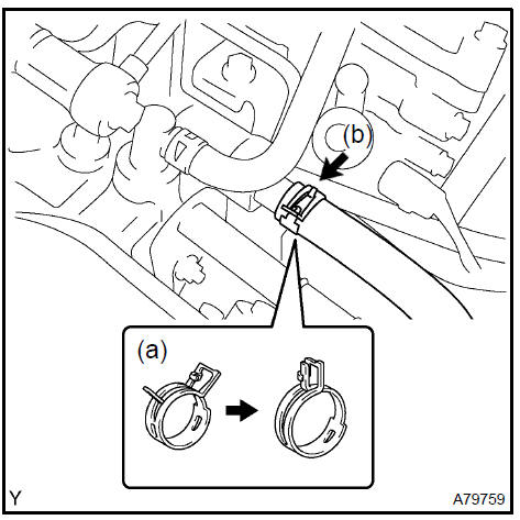
Disconnect heater inlet water hose
13. REMOVE INTAKE MANIFOLD
-
Remove the nut and disconnect the ground cable.
-
Disconnect the 6 fuel injector connectors.
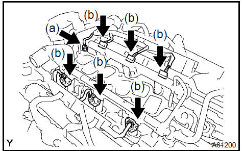
c. Uniformly loosen and remove the intake manifold’s 9 bolts and 2 nuts in the sequence shown in the illustration. Remove the intake manifold.

-
DISCONNECT RADIATOR HOSE INLET
-
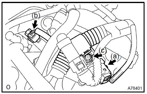
REMOVE WATER OUTLET
-
Disconnect the radiator hose inlet.
-
Disconnect the engine coolant temperature connector.
-
Remove the clamp.
-
Remove the 2 bolts, 2 nuts and 2 washers.
-
Lock the hose clamp as shown in the illustration and remove the water outlet together with the water by−pass hose No. 1.
-
Remove the 2 gaskets from the 2 cylinder heads.
-
REMOVE FRONT WHEEL RH
-
REMOVE FRONT FENDER APRON SEAL RH
-
REMOVE V (COOLER COMPRESSOR TO CRANKSHAFT PULLEY) BELT No.1
-
REMOVE VANE PUMP V BELT
-
REMOVE ENGINE MOVING CONTROL ROD
-
REMOVE ENGINE MOUNTING STAY No.2 RH
-
REMOVE GENERATOR BRACKET No.2
-
REMOVE CRANKSHAFT PULLEY
-
REMOVE TIMING BELT No.1 COVER
-
REMOVE TIMING BELT No.2 COVER
-
REMOVE ENGINE MOUNTING BRACKET RH
-
REMOVE TIMING BELT GUIDE No.2
-
REMOVE TIMING BELT
-
REMOVE TIMING BELT IDLER SUB−ASSY No.2
-
REMOVE CAMSHAFT TIMING PULLEY
-
REMOVE TIMING BELT No.3 COVER
-
REMOVE VANE PUMP ASSY
-
REMOVE IGNITION COIL ASSY
-
REMOVE CYLINDER HEAD COVER SUB−ASSY
-
REMOVE CAMSHAFT
-
REMOVE No.2 CAMSHAFT
-
REMOVE CYLINDER HEAD SUB−ASSY
-
Disconnect the VVT connector.
-
Disconnect the camshaft timing oil control valve connector.
-
Remove the nut and disconnect the engine wire harness clamp.
d. Using a socket hexagon wrench 8, remove the hexagon bolt.
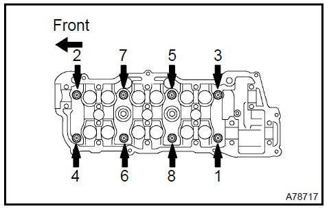
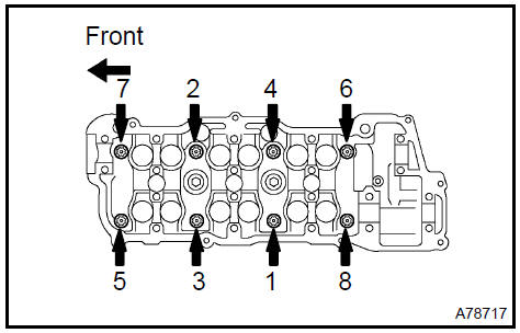
e. Uniformly loosen the 8 cylinder head bolts in the sequence shown in the illustration. Remove the 8 cylinder head bolts and plate washers.
NOTICE:
-
Be careful not to drop the washers into the cylinder head.
-
Head warpage or cracking could result from removing bolts in an incorrect order.
-
REMOVE CYLINDER HEAD GASKET
-
INSPECT CYLINDER HEAD SET BOLT
a. Using a vernier caliper, measure the tension portion diameter of the bolt.
Specified outside diameter: 8.75 to 9.05 mm (0.3445 to 0.3563 in.)
If the diameter is less than the minimum, replace the bolt.
Inspect cylinder head set bolt
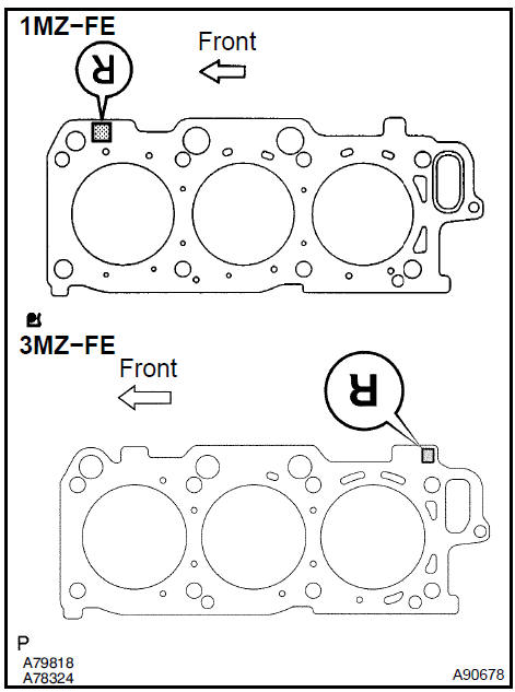
40. INSTALL CYLINDER HEAD GASKET
a. Place a new cylinder head gasket on the cylinder block with the R mark upside down, as shown in the illustration.
NOTICE:
-
Remove any oil from the contact surface.
-
Be careful of the installation direction.
-
To avoid damage to the gasket, place the cylinder head on the gasket carefully.
41. INSTALL CYLINDER HEAD SUB−ASSY
NOTICE: The cylinder head bolts are tightened in 2 successive steps.
-
Apply a light coat of engine oil on the threads of the cylinder head bolts.
-
Install the plate washers to the cylinder head bolts.
-
Uniformly install and tighten the 8 cylinder head bolts in the sequence shown in the illustration.
Torque: 54 N·m (550 kgf·cm, 40 ft·lbf)
-
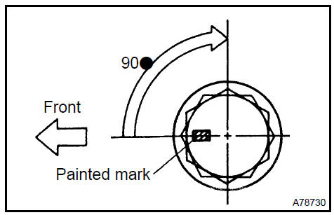
Mark the front side of each cylinder head bolt head with paint as shown in the illustration.
-
Retighten the cylinder head bolts by 90 in the same sequence as step c..
-
Check that each painted mark is now at a 90 angle to the front.
-
Using a socket hexagon wrench 8, install the hexagon bolt.
Torque: 19 N·m (189 kgf·cm, 14 ft·lbf)
-
Connect the engine wire harness clamp with the nut.
Torque: 8.4 N·m (85 kgf·cm, 74 in.·lbf)
-
INSTALL No.2 CAMSHAFT
-
INSTALL CAMSHAFT
-
INSTALL CYLINDER HEAD COVER SUB−ASSY
-
INSTALL IGNITION COIL ASSY Torque: 8.0 N·m (82 kgf·cm, 71 in.·lbf)
-
INSTALL VANE PUMP ASSY
-
INSTALL TIMING BELT No.3 COVER
-
INSTALL CAMSHAFT TIMING PULLEY
-
INSTALL TIMING BELT IDLER SUB−ASSY No.2 Torque: 43 N·m (438 kgf·cm, 32 ft·lbf)
-
INSPECT TIMING BELT
-
INSTALL TIMING BELT
-
INSTALL TIMING BELT TENSIONER ASSY
-
INSTALL TIMING BELT GUIDE No.2
-
INSTALL ENGINE MOUNTING BRACKET RH Torque: 28 N·m (286 kgf·cm, 21 ft·lbf)
-
INSTALL TIMING BELT No.2 COVER
-
INSTALL TIMING BELT No.1 COVER
-
INSTALL CRANKSHAFT PULLEY
-
INSTALL GENERATOR BRACKET No.2 Torque: 28 N·m (286 kgf·cm, 21 ft·lbf)
-
INSTALL ENGINE MOUNTING STAY No.2 RH
-
INSTALL ENGINE MOVING CONTROL ROD
-
INSTALL VANE PUMP V BELT
-
INSTALL V (COOLER COMPRESSOR TO CRANKSHAFT PULLEY) BELT No.1
-
INSPECT DRIVE BELT TENSION
-
INSTALL WATER OUTLET
-
Install 2 new gaskets to the 2 cylinder heads.
-
Install the water outlet together the with water by−pass hose No. 1 and unlock the hose clamp.
-
Tighten the 2 bolts, 2 nuts and 2 washers.
Torque: 15 N·m (153 kgf·cm, 11 ft·lbf)
-
Install the clamp.
-
Connect the engine coolant temperature connector.
-
Connect the radiator hose inlet.
65. INSTALL INTAKE MANIFOLD
-
Install the intake manifold with the 9 bolts, 2 nuts and 2 washers. Uniformly tighten the bolts and nuts in the sequence shown in the illustration.
Torque: 15 N·m (153 kgf·cm, 11 ft·lbf)
-
Retighten the water outlet mounting bolts and nuts.
Torque: 15 N·m (153 kgf·cm, 11 ft·lbf)
-
Install the ground cable with the nut.
Torque: 8.4 N·m (86 kgf·cm, 74 in.·lbf)
-
Connect the heater inlet water hose.
Install intake manifold
-
CONNECT FUEL PIPE SUB−ASSY No.1
-
INSTALL INTAKE AIR SURGE TANK
-
INSTALL AIR CLEANER ASSEMBLY WITH HOSE
-
CONNECT VACUUM HOSES
-
INSTALL FRONT SUSPENSION UPPER BRACE CENTER (W/ FRONT SUSPENSION BRACE UPPER CENTER) Torque: 80 N·m (816 kgf·cm, 59 ft·lbf)
-
INSTALL V−BANK COVER SUB−ASSY
-
INSTALL EXHAUST MANIFOLD SUB−ASSY RH
-
INSTALL EXHAUST PIPE ASSY FRONT
-
INSTALL EXHAUST PIPE No.1 SUPPORT BRACKET
-
INSTALL FRONT WHEEL RH
-
ADD ENGINE OIL
-
ADD ENGINE COOLANT
-
CHECK FOR ENGINE OIL LEAKS
-
CHECK FOR ENGINE COOLANT LEAKS
-
CHECK FOR FUEL LEAKS
-
CHECK FOR EXHAUST GAS LEAKS
-
INSPECT IGNITION TIMING
-
INSPECT ENGINE IDLE SPEED
-
INSPECT COMPRESSION
-
INSPECT CO/HC
Engine (2AZ−FE) (From July, 2003)
Timing gear case or timing chain case oil seal (2AZ−FE)(From July, 2003)
Engine rear oil seal (2AZ−FE)(From July, 2003)
Cylinder head assy (2AZ−FE) (From July, 2003)
Cylinder block assy (2AZ−FE)(From July, 2003)
Engine (1MZ−FE/3MZ−FE)
Drive belt (1MZ−FE/3MZ−FE)
Valve clearance (1MZ−FE/3MZ−FE)
Partial engine assy (1MZ−FE/3MZ−FE)
Partial engine assy (2AZ−FE)(From July, 2003)
Partial engine assy (1MZ−FE/3MZ−FE)
Timing belt (1MZ−FE/3MZ−FE)
Camshaft (RH BANK) (1MZ−FE/3MZ−FE)
Camshaft (LH BANK) (1MZ−FE/3MZ−FE)
Cylinder head gasket (1MZ−FE/3MZ−FE)
Cylinder head gasket No.2 (1MZ−FE/3MZ−FE)
Oil pump seal (1MZ−FE/3MZ−FE)
Engine rear oil seal (1MZ−FE/3MZ−FE)
Cylinder head assy (1MZ−FE/3MZ−FE)
Cylinder block assy (1MZ−FE/3MZ−FE)
Partial engine assy (2AZ−FE)(From July, 2003)
Drive belt (2AZ−FE)(From July, 2003)
Valve clearance (2AZ−FE)
Chain (2AZ−FE)(From July, 2003)
Camshaft (2AZ−FE)(From July, 2003)
Cylinder head gasket (2AZ−FE)(From July, 2003)
Toyota Camry XV30 (2002–2006) Service Manual
- Introduction
- Audio & visual system
- Automatic transmission / trans
- Brake
- Clutch
- Communication system
- Cooling
- Cruise control
- Drive shaft / propeller shaft
- Emission control
- Engine control system
- Engine hood/door
- Engine mechanical
- Exhaust
- Exterior/interior trim
- Front suspension
- Fuel
- Heater & air conditioner
- Ignition
- Instrument panel/meter
- Intake
- Lighting
- Lubrication
- Manual transmission/transaxle
- Parking brake
- Power steering
- Rear suspension
- Seat
- Service specifications
- Sliding roof/convertible
- Starting & charging
- Steering column
- Supplemental restraint system
- Theft deterrent & door lock
- Tire & wheel
- Windshield/windowglass/mirror
- Wiper & washer
- Wiring
Categories
