 Toyota Camry XV30 (2002–2006) Service ManualEngine mechanical
Partial engine assy (1MZ−FE/3MZ−FE)
Partial engine assy (1MZ−FE/3MZ−FE)
REPLACEMENT
-
WORK FOR PREVENTING GASOLINE FROM SPILLING OUT
-
REMOVE FRONT WHEELS
-
REMOVE ENGINE UNDER COVER RH
-
REMOVE ENGINE UNDER COVER LH
-
REMOVE FRONT FENDER APRON SEAL RH
-
DRAIN ENGINE OIL
-
DRAIN ENGINE COOLANT
-
DRAIN AUTOMATIC TRANSAXLE FLUID
-
REMOVE BATTERY
-
REMOVE V (COOLER COMPRESSOR TO CRANKSHAFT PULLEY) BELT No.1
-
REMOVE VANE PUMP V BELT
-
REMOVE ENGINE MOVING CONTROL ROD
a. Remove the 4 bolts and control rod.
Remove engine moving control rod
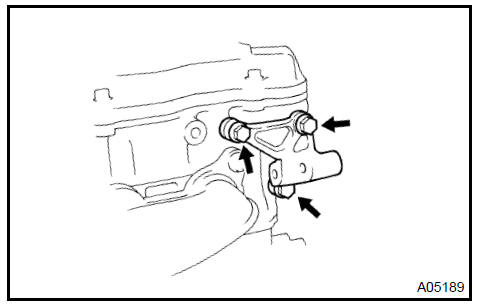
13. REMOVE ENGINE MOUNTING STAY No.2 RH
a. Remove the bolt, mounting stay No. 2 RH and mounting bracket No. 2 RH.
Remove engine mounting stay No.2 RH
14. REMOVE UNION TO CHECK VALVE HOSE
a. Remove the vacuum hose for the brake booster.
15. REMOVE V−BANK COVER SUB−ASSY
-
Using a 5 mm hexagon wrench, remove the 3 nuts.
-
Disconnect the 2 clips, and remove the cover.
Remove V-bank cover sub-assy
-
REMOVE AIR CLEANER INLET ASSY
-
REMOVE AIR CLEANER ASSEMBLY WITH HOSE
-
REMOVE AIR CLEANER BRACKET
-
REMOVE AIR CLEANER INLET No.1
-
REMOVE INTAKE AIR RESONATOR SUB−ASSY
-
SEPARATE FUEL PIPE SUB−ASSY No.1
a. Remove the fuel pipe clamp.
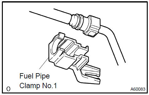
b. Disconnect the connector from the tube while pinching part A with fingers as shown in the illustration.
NOTICE:
-
Check for contamination in the pipe and around the connector. Clean if necessary and then disconnect the connector.
-
Disconnect the connector with your hands.
-
Do not bend, fold or rotate the nylon tube.
-
If the pipe and connector are stuck together, push and pull the connector until it comes free.
-
Put the pipe and connector ends in vinyl bags to prevent damage and contamination.
-
REMOVE RADIATOR HOSE INLET
-
REMOVE RADIATOR HOSE OUTLET
-
DISCONNECT OIL COOLER INLET HOSE
-
DISCONNECT OIL COOLER OUTLET HOSE
-
DISCONNECT HEATER INLET WATER HOSE
-
DISCONNECT HEATER OUTLET WATER HOSE
-
REMOVE GLOVE COMPARTMENT DOOR ASSY
-
DISCONNECT ENGINE WIRE
-
Disconnect the engine wire from the ECM and J/B.
-
Disconnect the engine wire from the engine room J/B.
-
Remove the nut and separate the wire harness.
-
Using a screwdriver, unlock the engine room junction block. Disconnect the engine wire by pulling it upward.
3. Disconnect the connector.
-
Pull out the engine wire.
-
Remove the body ground.
-
DISCONNECT FLOOR SHIFT CABLE TRANSMISSION CONTROL SELECT
-
DISCONNECT OIL RESERVOIR TO PUMP HOSE No.1
32. DISCONNECT STEERING GEAR OUTLET RETURN TUBE
-
REMOVE EXHAUST PIPE No.1 SUPPORT BRACKET
-
REMOVE EXHAUST PIPE ASSY FRONT
-
DISCONNECT FRONT STABILIZER LINK ASSY LH
-
Using a 6 mm socket hexagon wrench, hold the ball stud.
-
Remove the nut and disconnect the stabilizer link.
36. DISCONNECT FRONT STABILIZER LINK ASSY RH
HINT: Use the same procedures described for the LH side.
37. REMOVE FRONT AXLE HUB LH NUT
a. Using SST and a hammer, strike the lock nut covering to remove it.
SST 09930−00010
NOTICE:
-
Set the drive shaft’s groove so that it faces up. Then use the SST and hammer.
-
Remove the covering from the lock nut completely or the screw of the drive shaft may be damaged.
-
Do not sharpen the tip of the SST.
b. Using a 30 mm socket wrench, remove the lock nut.
Remove front axle hub LH nut
38. REMOVE FRONT AXLE HUB RH NUT
HINT: Use the same procedures described for the LH side.
39. DISCONNECT SPEED FRONT LH
a. Remove the bolt and disconnect the speed from the steering knuckle.
NOTICE: Keep the speed tip and connection free from foreign matter.
40. DISCONNECT SPEED FRONT RH
HINT: Use the same procedures described for the LH side.
41. DISCONNECT TIE ROD ASSY LH
-
Remove the cotter pin and nut.
-
Using SST, disconnect the tie rod end from the steering knuckle.
SST 09628−62011
NOTICE: Do not damage the dust cover of the ball joint.
Disconnect speed front RH
42. DISCONNECT TIE ROD ASSY RH
HINT: Use the same procedures described for the LH side.
43. DISCONNECT FRONT SUSPENSION ARM SUB−ASSY LOWER No.1 LH
-
Remove the bolt and 2 nuts, and separate the front suspension arm from the lower ball joint.
-
Using a plastic hammer, disconnect the drive shaft from the axle hub.
Disconnect front suspension arm sub-assy lower No.1 LH
44. DISCONNECT FRONT SUSPENSION ARM SUB−ASSY LOWER No.1 RH
HINT: Use the same procedures described for the LH side.
-
REMOVE STARTER ASSY
-
REMOVE EXHAUST PIPE SUPPORT BRACKET No.1
-
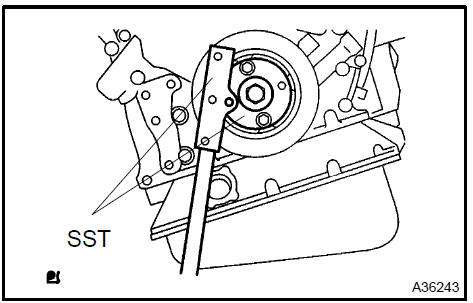
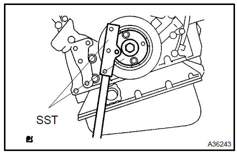
REMOVE DRIVE PLATE & TORQUE CONVERTER CLUTCH SETTING BOLT
-
Using SST, hold the crankshaft.
SST 09213−54015 (91651−60855), 09330−00021
-
Remove the 2 bolts and flywheel housing under cover.
c. Remove the 6 torque converter setting bolts.
48. DISCONNECT STEERING INTERMEDIATE SHAFT ASSY
a. Loosen the sliding yoke bolt.
-
Place matchmarks on the steering intermediate shaft and control valve shaft.
-
Remove the bolt and disconnect the steering intermediate shaft.
d. To prevent the steering wheel from rotating, fix the wheel with the seat belt.
NOTICE: If the steering wheel is not fixed, the spiral cable will be damaged.
-
REMOVE GENERATOR ASSY
-
REMOVE GENERATOR BRACKET No.2
-
REMOVE GENERATOR BELT ADJUSTING BAR
a. Remove the 2 bolts, 2 nuts and the adjusting bar.
Remove generator belt adjusting bar
52. DISCONNECT COMPRESSOR AND MAGNETIC CLUTCH
-
Remove the bolt, nut and adjusting bar bracket.
-
Remove the 3 bolts and disconnect the compressor.
HINT: Hang up the hoses instead of detaching them.
53. REMOVE ENGINE ASSEMBLY WITH TRANSAXLE
a. Set the engine lifter.
b. Remove the 4 bolts, 2 nuts, and frame side rail plate sub− assembly RH and LH.
-
Remove the 4 bolts, 2 nuts, and front suspension member brace rear RH and LH.
-
Carefully, remove the engine assembly from the vehicle.
-
Install the engine hanger as shown in the illustration.
No. 2 engine hanger: Part No. 12282−20020 Bolt: Part No. 91621−60822 Torque: 20 N·m (204 kgf·cm, 15 ft·lbf)
-
Using a chain block and an engine sling device, hang the engine assembly.
54. REMOVE VANE PUMP ASSY
-
Remove the power steering oil pressure harness.
-
Remove the pressure feed tube clamp.
-
Remove the 2 bolts and vane pump.
Remove vane pump assy
55. REMOVE FRONT FRAME ASSY
a. Remove the 2 nuts and disconnect the engine mounting insulator RH and LH.
b. Remove the bolt and disconnect the engine mounting insulator FR.
-
REMOVE FRONT DRIVE SHAFT ASSY LH
-
REMOVE FRONT DRIVE SHAFT ASSY RH
-
REMOVE ENGINE WIRE
-
REMOVE AUTOMATIC TRANSAXLE ASSY
-
REMOVE DRIVE PLATE & RING GEAR SUB−ASSY
-
INSTALL ENGINE STAND
-
REMOVE INTAKE AIR SURGE TANK
-
Disconnect the throttle motor connector.
-
Disconnect the water bypass hose No. 3.
-
Disconnect the water bypass hose No. 2.
-
Disconnect the union to check valve hose.
e. Disconnect the ventilation hose.
f. Remove the 3 nuts and separate the pressure feed tube.
-
Remove the 2 bolts and engine hunger No. 1.
-
Remove the 2 bolts and surge tank stay No. 1.
-
Remove the 2 bolts and surge tank stay No. 2.
-
Using a socket hexagon wrench 8, remove the 4 bolts.
-
Remove the 2 nuts, emission control valve bracket and surge tank.
-
Remove the gasket from the surge tank.
63. INSPECT INTAKE AIR SURGE TANK
a. Using a precision straight edge and feeler gauge, measure the surface contacting the cylinder head for warpage.
Maximum warpage: 0.10 mm (0.0039 in.)
If the warpage is greater than the maximum, replace the manifold.
Inspect intake air surge tank
-
REMOVE IGNITION COIL ASSY
-
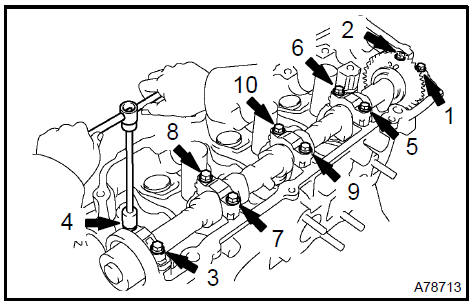
REMOVE INTAKE MANIFOLD
-
Remove the nut and disconnect the ground cable.
-
Disconnect the 6 fuel injector connectors.
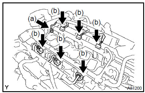
c Uniformly, loosen and remove the 9 bolts and 2 nuts in the sequence shown in the illustration. Remove the intake manifold.
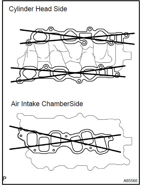
66. INSPECT INTAKE MANIFOLD
a. Using a precision straight edge and feeler gauge, measure the surface contacting the cylinder head and air intake surge tank for warpage.
Maximum warpage:
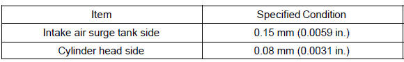
If warpage is greater than the maximum, replace the manifold.
-
REMOVE WATER OUTLET
-
REMOVE EXHAUST MANIFOLD SUB−ASSY RH
-
Disconnect the A/F connector.
-
Remove the 3 bolts and insulator.
-
Uniformly loosen and remove the 6 nuts in the sequence shown in the illustration.
-
Remove the manifold and gasket.
69. INSPECT EXHAUST MANIFOLD SUB−ASSY RH
a. Using a precision straight edge and feeler gauge, measure the surface contacting the cylinder head for warpage.
Maximum warpage: 0.50 mm (0.0196 in.)
If the warpage is greater than the maximum, replace the manifold.
Inspect exhaust manifold sub-assy RH
70. REMOVE MANIFOLD STAY No.2
a. Remove the 2 bolts and manifold stay.
 Remove manifold stay No.2
71. REMOVE EXHAUST MANIFOLD HEAT INSULATOR No.2
a. Remove the 2 bolts and insulator.
b. Remove the bolt, nut and insulator.
72. REMOVE EXHAUST MANIFOLD CONVERTER SUB−ASSY No.2
-
Uniformly loosen and remove the 7 nuts in the sequence shown in the illustration.
-
Remove the converter and gasket.
Remove exhaust manifold converter sub-assy No.2
73. INSPECT EXHAUST MANIFOLD CONVERTER SUB−ASSY No.2
a. Using a precision straight edge and feeler gauge, measure the surface contacting the cylinder head for warpage.
Maximum warpage: 0.50 mm (0.0196 in.)
If the warpage is greater than the maximum, replace the manifold.
Inspect exhaust manifold converter sub-assy No.2
-
REMOVE DRIVE SHAFT BEARING BRACKET
-
REMOVE PUMP BRACKET
a. Remove the 3 bolts and pump bracket.
Remove pump bracket
-
REMOVE GENERATOR BRACKET No.1
-
REMOVE COMPRESSOR MOUNTING BRACKET No.1
-
REMOVE WATER INLET PIPE
-
REMOVE WATER INLET
-
REMOVE THERMOSTAT
-
REMOVE ENGINE OIL PRESSURE SWITCH ASSY
a. Remove the oil pressure switch.
82. REMOVE KNOCK
-
1MZ−FE: Using SST, remove the 2 s.
SST 09816−30010
-
3MZ−FE: Remove the 2 nuts and 2 s.
-
REPLACE PARTIAL ENGINE ASSY
-
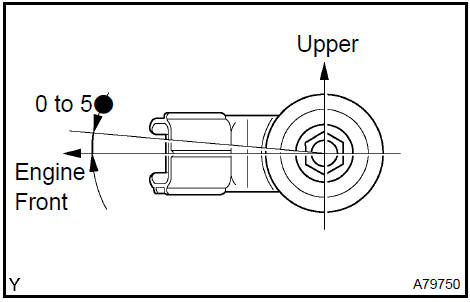
INSTALL KNOCK
a. 1MZ−FE: Using SST, install the 2 knock control s.
SST 09816−30010 Torque: 39 N·m (398 kgf·cm, 29 ft·lbf)
b. 3MZ−FE: Install the 2 knock s with the 2 nuts, as shown in the illustration.
Torque: 20 N·m (199 kgf·cm, 14 ft·lbf)
85. INSTALL ENGINE OIL PRESSURE SWITCH ASSY
-
Clean the threads of the oil pressure switch. Apply adhesive to 2 or 3 threads of the oil pressure switch.
Adhesive: Part No. 08833−00080 THREE BOND 1344, LOCTITE 242 or equivalent
-
Install the oil pressure switch.
Torque: 15 N·m (152 kgf·cm, 11 ft·lbf)
Install engine oil pressure switch assy
-
INSTALL THERMOSTAT
-
INSTALL WATER INLET
-
INSTALL WATER INLET PIPE
-
INSTALL COMPRESSOR MOUNTING BRACKET No.1 Torque: 25 N·m (255 kgf·cm, 18 ft·lbf)
-
INSTALL GENERATOR BRACKET No.1 Torque: 58 N·m (591 kgf·cm, 43 ft·lbf)
-
INSTALL PUMP BRACKET Torque: 32 N·m (326 kgf·cm, 24 ft·lbf)
Install pump bracket
-
INSTALL DRIVE SHAFT BEARING BRACKET Torque: 64 N·m (653 kgf·cm, 47 ft·lbf)
-
INSTALL EXHAUST MANIFOLD CONVERTER SUB−ASSY No.2
-
Install a new gasket and the converter sub−assy No. 2 with the 7 nuts. Uniformly, tighten the 7 nuts in the sequence shown in the illustration.
Torque: 49 N·m (500 kgf·cm, 36 ft·lbf)
-
Retighten nuts 1 and 2 as shown in the illustration.
Install exhaust manifold converter sub-assy No.2
-
INSTALL EXHAUST MANIFOLD HEAT INSULATOR No.2 Torque: 8.5 N·m (87 kgf·cm, 55 in.·lbf)
-
INSTALL MANIFOLD STAY No.2 Torque: 34 N·m (347 kgf·cm, 25 ft·lbf)
-
INSTALL EXHAUST MANIFOLD SUB−ASSY RH
-
Install a new gasket and the exhaust manifold RH. Uniformly tighten the 5 nuts in the sequence shown in the illustration.
Torque: 49 N·m (500 kgf·cm, 36 ft·lbf)
-
Retighten nuts 1 and 2 shown in the illustration.
Install exhaust manifold sub-ass RH
-
INSTALL WATER OUTLET
-
INSTALL INTAKE MANIFOLD
-
Install the intake manifold with the 9 bolts, 2 nuts and 2 washers. Uniformly tighten the bolts and nuts in the sequence shown in the illustration.
Torque: 15 N·m (153 kgf·cm, 11 ft·lbf)
-
Retighten the water outlet mounting bolts and nuts.
Torque: 15 N·m (153 kgf·cm, 11 ft·lbf)
-
Install the ground cable with the nut.
Torque: 8.4 N·m (86 kgf·cm, 74 in.·lbf)
-
Connect the heater inlet water hose.
Install intake manifold
-
INSTALL IGNITION COIL ASSY Torque: 8.0 N·m (82 kgf·cm, 71 in.·lbf)
-
INSTALL INTAKE AIR SURGE TANK
-
Install a new gasket to the intake air surge tank.
-
Install the intake air surge tank and emission control valve bracket with the 2 nuts.
Torque: 28 N·m (286 kgf·cm, 21 ft·lbf)
-
Using a socket hexagon wrench 8, tighten the 4 bolts.
Torque: 28 N·m (286 kgf·cm, 21 ft·lbf)
-
Install the surge tank stay No. 2 with the 2 bolts.
Torque: 20 N·m (199 kgf·cm, 15 ft·lbf)
-
Install the surge tank stay No. 1 with the 2 bolts.
Torque: 20 N·m (199 kgf·cm, 15 ft·lbf)
-
Install the engine hunger No. 1 with the 2 bolts.
Torque: 20 N·m (199 kgf·cm, 15 ft·lbf)
-
Install the pressure feed tube with the 3 nuts.
Torque: 7.8 N·m (80 kgf·cm, 69 in.·lbf)
-
Connect the ventilation hose.
-
Connect the union to check valve hose.
-
Connect the water bypass hose No. 2.
-
Connect the water bypass hose No. 3.
-
Connect the throttle motor connector.
-
INSTALL DRIVE PLATE & RING GEAR SUB−ASSY
-
INSTALL AUTOMATIC TRANSAXLE ASSY
-
INSTALL FRONT DRIVE SHAFT ASSY RH
-
INSTALL FRONT DRIVE SHAFT ASSY LH
-
INSTALL FRONT FRAME ASSY
a. Install the engine mounting insulator RH and LH with the 2 nuts.
Torque: 95 N·m (969 kgf·cm, 70 ft·lbf)
b. Install the engine mounting insulator FR with the bolt.
Torque: 87 N·m (887 kgf·cm, 64 ft·lbf)
106. INSTALL VANE PUMP ASSY
a. Install the vane pump with the 2 bolts.
Torque: 43 N·m (439 kgf·cm, 32 ft·lbf)
HINT: After adjusting the V−ribbed belt, tighten bolt A.
Install vane pump assy
107. INSTALL ENGINE ASSEMBLY WITH TRANSAXLE
-
Set the engine assembly with transaxle on the engine lifter.
-
Install the engine assembly to the vehicle.
-
Install the frame side rail plate RH and LH with the 4 bolts and 2 nuts.
Torque:
85 N·m (867 kgf·cm, 63 ft·lbf) for bolt A 32 N·m (326 kgf·cm, 24 ft·lbf) for bolt B and nut
d. Install the front suspension member brace rear RH and LH with the 4 bolts and 2 nuts.
Torque:
85 N·m (867 kgf·cm, 63 ft·lbf) for bolt C
32N·m (326 kgf·cm, 24 ft·lbf) for bolt D and nut
108. INSTALL COMPRESSOR AND MAGNETIC CLUTCH
-
Install the compressor with the 3 bolts.
Torque: 25 N·m (250 kgf·cm, 18 ft·lbf)
-
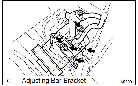
Install the adjusting bar bracket with the bolt and nut.
Torque:
25 N·m (250 kgf·cm, 18 ft·lbf) for bolt 26 N·m (260 kgf·cm, 19 ft·lbf) for nut
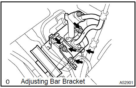
Install compressor and magnetic clutch
109. INSTALL GENERATOR BELT ADJUSTING BAR
a. Install the adjusting bar with the 2 bolts and 2 nuts.
Torque:
43 N·m (438 kgf·cm, 32 ft·lbf) for nut A
18 N·m (184 kgf·cm, 13 ft·lbf) for bolt B
8.0 N·m (82 kgf·cm, 71 in.·lbf) for bolt C
Install generator belt adjusting bar
-
INSTALL GENERATOR BRACKET No.2 Torque: 28 N·m (286 kgf·cm, 21 ft·lbf)
-
INSTALL GENERATOR ASSY
-
INSTALL STEERING INTERMEDIATE SHAFT ASSY
a. Align the matchmarks on the intermediate shaft and control valve shaft, and install the bolt.
Torque: 35 N·m (357 kgf·cm, 26 ft·lbf)
b. Tighten the sliding yoke bolt.
Torque: 35 N·m (357 kgf·cm, 26 ft·lbf)
113. INSTALL DRIVE PLATE & TORQUE CONVERTER CLUTCH SETTING BOLT
-
Using SST, hold the crankshaft.
SST 09213−54015 (91651−60855), 09330−00021
-
Using kerosene or gasoline, clean the bolts thoroughly.
-
Apply adhesive to 2 or 3 threads of the bolt end.
Adhesive:
Part No. 08833−00070, THREE BOND 1324 or equivalent
d. Install the 6 torque converter set bolts.
Torque: 41 N·m (418 kgf·cm, 30 ft·lbf)
NOTICE: First tighten the green colored bolt and then tighten the 5 bolts.
e. Install the flywheel housing under cover with the 2 bolts.
Torque: 7.8 N·m (80 kgf·cm, 69 in.·lbf)
-
INSTALL EXHAUST PIPE SUPPORT BRACKET No.1 Torque: 21 N·m (214 kgf·cm, 15 ft·lbf)
-
INSTALL STARTER ASSY
-
INSTALL FRONT SUSPENSION ARM SUB−ASSY LOWER No.1 LH
-
Install the drive shaft to the steering knuckle.
-
Install the suspension lower arm with the bolt and 2 nuts.
Torque: 75 N·m (764 kgf·cm, 55 ft·lbf)
Install front suspension arm sub-assy lower No.1 LH
117. INSTALL FRONT SUSPENSION ARM SUB−ASSY LOWER No.1 RH
HINT: Use the same procedures described for the LH side.
118. INSTALL TIE ROD ASSY LH
a. Connect the tie rod end to the steering knuckle and install a new castle nut.
Torque: 49 N·m (500 kgf·cm, 36 ft·lbf)
NOTICE:
-
Prevent any lubricant from contacting the thread and the taper portions.
-
After tightening the castle nut, tighten it to the additional direction within 60 to put into a cotter pin.
b. Insert a new cotter pin.
119. INSTALL TIE ROD ASSY RH
HINT: Use the same procedures described for the LH side.
-
INSTALL SPEED FRONT LH
-
INSTALL SPEED FRONT RH
HINT: Use the same procedures described for the LH side.
122. INSTALL FRONT AXLE HUB LH NUT
-
Using a 30 mm socket wrench, install a new hub nut.
Torque: 294 N·m (2,998 kgf·cm, 217 ft·lbf)
-
Using a chisel and hammer, tapped the front axle hub LH nut.
Install front axle hub LH nut
123. INSTALL FRONT AXLE HUB RH NUT
HINT: Use the same procedures described for the LH side.
124. INSTALL FRONT STABILIZER LINK ASSY LH
a. Using a 6 mm socket hexagon wrench, hold the ball stud, and install the nut.
Torque: 74 N·m (755 kgf·cm, 55 ft·lbf)
125. INSTALL FRONT STABILIZER LINK ASSY RH
HINT: Use the same procedures described for the LH side.
-
INSTALL EXHAUST PIPE ASSY FR
-
INSTALL EXHAUST PIPE No.1 SUPPORT BRACKET
-
CONNECT FUEL PIPE SUB−ASSY No.1
a. Push in the fuel tube connector to the fuel pipe until connector makes a ”click” sound.
NOTICE:
-
Check for damage or contamination on the connected part of the pipe.
-
After having finished the connection, check if the pipe and the connector are securely connected by trying to pull them apart.
b. Install the fuel pipe clamp.
Connect fuel pipe sub-assy No.1
-
INSTALL AIR CLEANER ASSEMBLY WITH HOSE
-
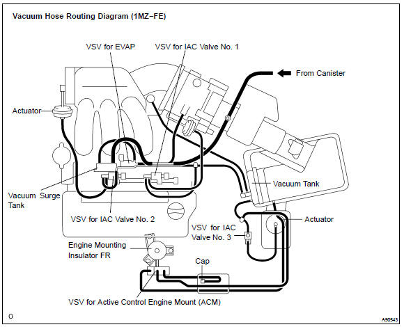
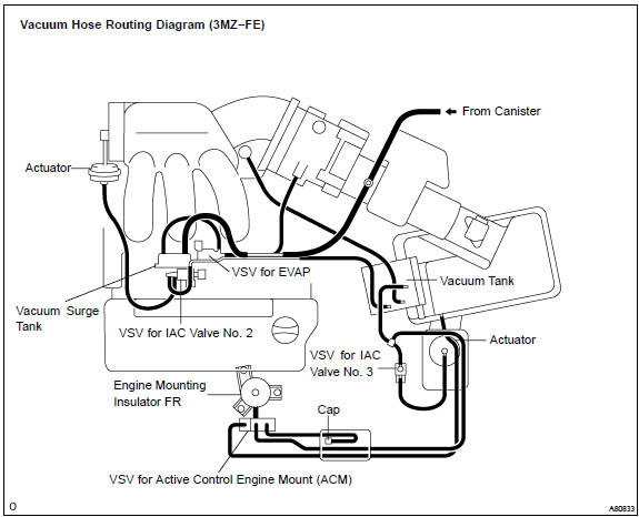
CONNECT VACUUM HOSES
131. INSTALL V−BANK COVER SUB−ASSY
a. Using a 5 mm socket hexagon wrench, install the V−bank cover with the 2 nuts.
Torque: 7.9 N·m (81 kgf·cm, 70 in.·lbf)
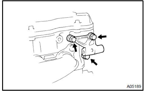
132. INSTALL ENGINE MOUNTING STAY No.2 RH
a. Install the mounting stay and mounting bracket with the bolt.
Torque: 64 N·m (653 kgf·cm, 47 ft·lbf)
Install engine mounting stay No.2 RH
133. INSTALL ENGINE MOVING CONTROL ROD
a. Install the control rod and bracket with the 4 bolts.
Torque:
64 N·m (653 kgf·cm, 47 ft·lbf) for bolt A
23 N·m (235 kgf·cm, 17 ft·lbf) for bolt B
Install engine moving control rod
-
INSTALL VANE PUMP V BELT
-
INSTALL V (COOLER COMPRESSOR TO CRANKSHAFT PULLEY) BELT No.1
-
INSPECT DRIVE BELT TENSION
-
INSTALL FRONT WHEELS
-
ADD AUTOMATIC TRANSAXLE FLUID
-
ADD ENGINE OIL
-
ADD ENGINE COOLANT
-
ADD POWER STEERING FLUID
-
BLEED POWER STEERING FLUID
-
CHECK FOR OIL LEAKS
-
CHECK FOR ENGINE COOLANT LEAKS
-
INSPECT FOR FUEL LEAKS
-
CHECK FOR EXHAUST GAS LEAKS
-
INSPECT AND ADJUST FRONT WHEEL ALIGNMENT
-
INSPECT IGNITION TIMING
-
INSPECT ENGINE IDLE SPEED
-
150. INSPECT CO/HC
-
CHECK ABS SPEED SIGNAL
OVERHAUL
-
REMOVE SPARK PLUG
-
REMOVE OIL FILLER CAP SUB−ASSY
-
REMOVE OIL FILLER CAP GASKET
-
REMOVE CYLINDER HEAD COVER SUB−ASSY LH
-
REMOVE CYLINDER HEAD COVER GASKET No.2
-
REMOVE CYLINDER HEAD COVER SUB−ASSY
-
REMOVE CYLINDER HEAD COVER GASKET
-
REMOVE VENTILATION VALVE SUB−ASSY
-
REMOVE CAMSHAFT TIMING OIL CONTROL VALVE ASSY
-
REMOVE VVT
-
Remove the .
-
Remove the O−ring from the .
-
REMOVE OIL LEVEL GAGE SUB−ASSY
-
REMOVE OIL LEVEL GAGE GUIDE
-
REMOVE CRANKSHAFT PULLEY
a. Using SST, loosen the pulley bolt.
SST 09213−54015 (91651−60855), 09330−00021
b. Using SST and the pulley bolt, remove the pulley.
SST 09950−50013 (09951−05010, 09952−05010, 09953−05020, 09954−05031)
NOTICE: Before using SST, apply lubricating oil on the threads and tip of the center bolt 150.
-
REMOVE TIMING BELT No.1 COVER
-
REMOVE TIMING BELT No.2 COVER
-
REMOVE ENGINE MOUNTING BRACKET RH
-
REMOVE TIMING BELT GUIDE No.2
-
REMOVE TIMING BELT
a. Set the No. 1 cylinder to TDC/compression.
-
Temporarily install the crankshaft pulley bolt and washer to the crankshaft.
-
Turn the crankshaft clockwise, and align the timing mark of the crankshaft timing pulley with the oil pump body.
3. Check that timing marks of the camshaft timing pulleys and No. 3 timing belt cover are aligned.
If not, turn the crankshaft 1 revolution (360 ).
4. Remove the crankshaft pulley bolt.
b) If reusing the timing belt, check that there are 4 installation marks on the timing belt as shown in the illustration.
1. If the installation marks have disappeared, put new installation marks on the timing belt before removing.
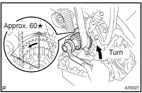
c. Set the No. 1 cylinder to approximately 60 BTDC/ compression.
1. Turn the crankshaft counterclockwise by approximately 60 .
NOTICE: With timing belt removed: The crankshaft pulley must be at the correct angle to avoid damage in later steps. If the crankshaft pulley is at the wrong angle and the camshaft timing pulley and the camshaft are removed, the piston head and valve head may come in contact and damaged.
d. Remove the timing belt tensioner.
NOTICE: Do not reinstall the tensioner with its plunger extended.
e. Remove the timing belt in this order.
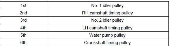
19. REMOVE TIMING BELT IDLER SUB−ASSY No.1
a. Using a socket hexagon wrench 10, remove the pivot bolt, timing belt idler No. 1 and plate washer.
-
REMOVE TIMING BELT IDLER SUB−ASSY No.2
-
REMOVE CRANKSHAFT POSITION
-
REMOVE CAMSHAFT TIMING PULLEY
a. Using SST, remove the bolt and RH timing pulley.
SST 09960−10010 (09962−01000, 09963−01000)
b. Using SST, remove the bolt and LH timing pulley.
SST 09960−10010 (09962−01000, 09963−01000)
HINT: Arrange the camshaft timing pulleys (RH and LH sides) so that they can be returned to the original locations when reassembling.
-
REMOVE TIMING BELT No.3 COVER
-
REMOVE TIMING BELT IDLER BRACKET
-
REMOVE CRANKSHAFT TIMING PULLEY
-
Remove the bolt and the timing belt plate.
-
Install the pulley bolt to the crankshaft.
-
Using SST, remove the crankshaft timing pulley.
SST 09950−50013 (09951−05010, 09952−05010, 09953−05020, 09954−05011)
NOTICE:
-
Do not scratch the part of the crankshaft timing pulley.
-
Before using SST, apply lubricating oil on the threads and tip of the center bolt 150.
Remove crankshaft timing pulley
26. REMOVE WATER PUMP ASSY
a. Remove the 3 bolts and 3 nuts, then remove the water pump and the gasket.
Remove water pump assy
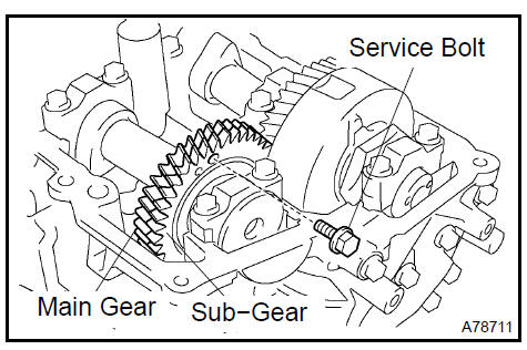
27. REMOVE CAMSHAFT
NOTICE: Since the thrust clearance of the camshaft is small, the camshaft must be kept level while it is being removed. If the camshaft is not kept level, damage to the cylinder head or to the camshaft may result. To avoid this, the following steps should be carried out.
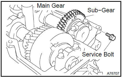
a. Align the camshaft drive and driven gear’s timing marks (2 dot marks each) by turning the camshaft with a wrench.
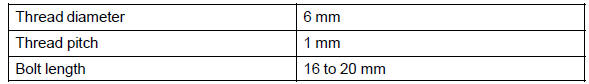
b. Secure the exhaust camshaft sub−gear to the main gear with a service bolt.
Recommended service bolt:
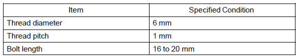
Torque: 5.4 N·m (55 kgf·cm, 48 in.·lbf)
HINT: When removing the camshaft, make certain that the torsional spring force of the sub gear has been eliminated by installation of the service bolt.
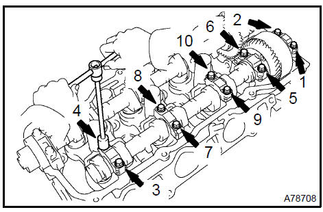
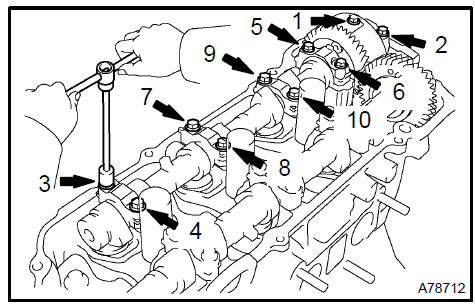
c. Uniformly loosen and remove the 10 bearing cap bolts in the sequence shown in the illustration. Remove the 5 bearing caps and the camshaft.
NOTICE:
-
Do not pry out the camshaft.
-
Be careful not to damage the portion of the cylinder head receiving the shaft thrust.
28. REMOVE No.2 CAMSHAFT
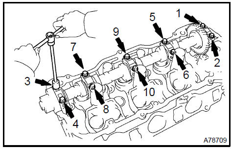
a. Uniformly loosen and remove the 10 bearing cap bolts in the sequence shown in the illustration. Remove the 5 bearing caps and the No. 2 camshaft.
NOTICE:
-
Do not pry out the camshaft.
-
Be careful not to damage the portion of the cylinder head receiving the shaft thrust.
b. Remove the oil seal from the No. 2 camshaft.
29. REMOVE No.3 CAMSHAFT SUB−ASSY
NOTICE: Since the thrust clearance of the camshaft is small, the camshaft must be kept level while it is being removed. If the camshaft is not kept level, damage to the cylinder head or to the camshaft may result. To avoid this, the following steps should be carried out.
a. Align the camshaft drive and driven gear’s timing marks (1 dot mark each) by turning the camshaft with a wrench.
b. Secure the exhaust camshaft sub−gear to the main gear with a service bolt.
Recommended service bolt:
Torque: 5.4 N·m (55 kgf·cm, 48 in.·lbf)
HINT: When removing the camshaft, make certain that the torsional spring force of the sub gear has been eliminated by installation of the service bolt.
c. Uniformly loosen and remove the 10 bearing cap bolts in the sequence shown in the illustration. Remove the 5 bearing caps and the No. 3 camshaft.
NOTICE:
-
Do not pry out the camshaft.
-
Be careful not to damage the portion of the cylinder head receiving the shaft thrust.
30. REMOVE No.4 CAMSHAFT SUB−ASSY
a. Uniformly loosen and remove the 10 bearing cap bolts in the sequence shown in the illustration. Remove the 5 bearing caps and the No. 4 camshaft.
NOTICE:
-
Do not pry out the camshaft.
-
Be careful not to damage the portion of the cylinder head receiving the shaft thrust.
b. Remove the oil seal from the No. 4 camshaft.
Remove No.4 Camshaft sub-assy
31. INSPECT CAMSHAFT TIMING GEAR ASSY
-
Clamp the camshaft in a vise on the hexagonal lobe.
-
Check that the VVT−i does not turn.
-
Cover all the oil ports with vinyl tape except the port on the advanced angle side (nearest to the convex portion) shown in the illustration.
-
Using an air gun, apply about 100 kPa (1 kgf/cm2, 14 psi) of air pressure to the port on the advanced angle side.
NOTICE: Some oil spraying will occur. Contain the spray with a shop rag.
HINT: This operation releases the lock pin for the extreme retarded angle lock.
e. Under the condition above, check that the VVT−i can be turned by hand to the advanced angle side, the direction of the white arrow in the illustration.
Standard: Must turn
HINT: The VVT−i will turn to the advanced angle side without applying force by hand depending on the force of the air pressure applied.
Also, if applying pressure to the oil path is difficult as a result of air leakage from the port, the lock−pin may be difficult to release.
-
Check that the VVT−i moves freely within a 30 range.
Avoid moving the VVT−i unit to the extreme retarded angle position as the lock−pin will re−engage.
Standard: Smooth movable range is about 30
-
Turn VVT−i by hand and lock it at the extreme retarded angle position.
32. REMOVE CAMSHAFT TIMING GEAR ASSY
NOTICE: Do not remove or install the timing gear (VVT−i) unless you are replacing the VVT−i or the camshaft.
a. Clamp the camshaft in a vise on the hexagonal lobe.
NOTICE: Do not damage the camshaft.
b. Using a 46 mm socket wrench, remove the lock nut by turning it clockwise.
NOTICE:
-
Remove it with the lock−pin engaged and locked at the extreme retarded angle position.
-
The lock nut has LH threads.
-
Only use the socket wrench. Other tools will deform the cam angle rotor.
c. Remove the timing gear (VVT−i).
NOTICE: Never remove the 3 bolts on the gear.
If it is difficult to remove the VVT−i, tap it lightly using a plastic− faced hammer and then remove it.
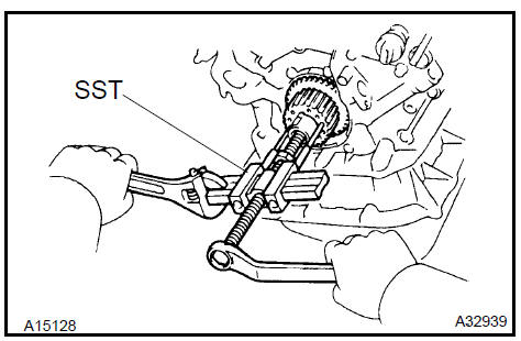
33. REMOVE CAMSHAFT SUB GEAR
a. Clamp the camshaft in a vise on the hexagonal lobe.
NOTICE: Be careful not to damage the camshaft.
b. Using SST, turn the sub gear counterclockwise, and remove the service bolt.
SST 09960−10010 (09962−01000, 09963−00500)
-
Using snap ring pliers, remove the snap ring.
-
Remove the wave washer, camshaft sub gear and camshaft gear bolt washer.
HINT: Arrange the camshaft sub gears and gear bolt washers (RH and LH sides) so that they can be returned to the original location when reassembling.
-
REMOVE ENGINE HANGER No.2
-
REMOVE CYLINDER HEAD COVER REAR
-
REMOVE OIL CONTROL VALVE FILTER
a. Remove the plug, gasket and valve filter.
Remove oil control valve filter
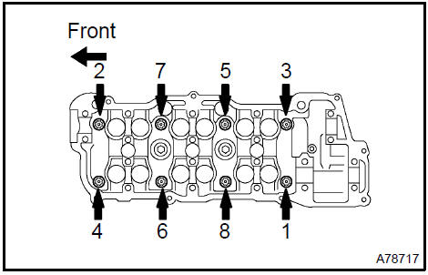
37. REMOVE CYLINDER HEAD SUB−ASSY
a. Using a socket hexagon wrench 8, remove the hexagon bolt.
b. Uniformly loosen the 8 cylinder head bolts in the sequence shown in the illustration. Remove the 8 cylinder head bolts and plate washers.
NOTICE:
-
Be careful not to drop washers into the cylinder head.
-
Head warpage or cracking could result from removing bolts in an incorrect order.
-
REMOVE CYLINDER HEAD GASKET
-
REMOVE CYLINDER HEAD LH
a. Using a socket hexagon wrench 8, remove the hexagon bolt.
b. Uniformly loosen the 8 cylinder head bolts in the sequence shown in the illustration. Remove the 8 cylinder head bolts and plate washers.
NOTICE:
-
Be careful not to drop washers into the cylinder head.
-
Head warpage or cracking could result from removing bolts in an incorrect order.
-
REMOVE CYLINDER HEAD GASKET No.2
-
REMOVE WATER INLET HOUSING
a. Uniformly loosen and remove the 8 bolts and 2 nuts in the sequence shown in the illustration. Remove the water inlet housing.
Remove water inlet housing
42. REMOVE OIL FILTER SUB−ASSY
-
Using SST, remove the oil filter.
SST 09228−07501
-
Using a socket hexagon wrench 12, remove the oil filter union.
Remove oil filter sub-assy
-
REMOVE OIL PAN DRAIN PLUG
-
REMOVE OIL PAN SUB−ASSY No.2
a. Remove the 10 bolts and 2 nuts.
b. Insert the blade of SST between oil pan No. 1 and oil pan No. 2, cut off the sealer and remove the oil pan No. 2.
SST 09032−00100
NOTICE:
-
Do not damage the contact surface of oil pan No. 1 and oil pan No. 2.
-
Do not damage the flange portion of oil pan No. 2 during removal.
45. REMOVE OIL STRAINER SUB−ASSY
a. Remove the bolt and 2 nuts, then remove the oil strainer and the gasket.
46. REMOVE OIL PAN SUB−ASSY
a. Uniformly loosen and remove the 15 bolts and 2 nuts in the sequence shown in the illustration.
b. Using a screwdriver, remove the oil pan by prying between the cylinder block and the oil pan.
NOTICE: Be careful not to damage the contact surfaces of the oil pan and cylinder block.

-
REMOVE OIL PAN BAFFLE PLATE
-
REMOVE ENGINE REAR OIL SEAL RETAINER
-
Uniformly loosen and remove the 6 bolts.
-
Using a screwdriver, remove the oil seal retainer by prying between the oil seal retainer and the main bearing cap.
Remove engine rear oil seal retainer
49. REMOVE ENGINE REAR OIL SEAL
a. Using a screwdriver and a hammer, tap out the oil seal.
Remove engine rear oil seal
50. REMOVE OIL PUMP ASSY
-
Remove the 9 bolts.
-
Using a screwdriver, remove the oil pump by prying between the oil pump and the main bearing cap.
-
Remove the O−ring.
Remove oil pump assy
51. REMOVE OIL PUMP SEAL
a. Using a screwdriver, pry out the oil seal.
Remove oil pump seal
52. REMOVE SPARK PLUG TUBE GASKET
a. Bend up the tab on the ventilation baffle plate which prevents the gasket from slipping out.
NOTICE: Be careful not to damage the baffle plate of the cylinder head cover.
b. Using a screwdriver and a hammer, tap out the gasket.
c. Using needle−nose pliers, pry out the gasket.
NOTICE: Be careful not to damage the cylinder head cover.
53. INSPECT TIMING BELT
NOTICE:
-
Do not bend, twist or turn the timing belt inside out.
-
Do not allow the timing belt to come into contact with oil, water or steam.
-
Do not utilize timing belt tension when installing or removing the mounting bolt of the camshaft timing pulley.
Check the belt for any defects, as shown in the illustrations.
Also, check these points below.
a. If there is premature parting:
-
Check for proper installation.
-
Check the timing cover gasket for damage and proper installation.
-
If the belt teeth are cracked or damaged, check to see if either camshaft is locked.
-
If there is noticeable wear or cracks on the belt face, check to see if there are nicks on the side of the idler pulley lock and water pump.
-
If there is wear or damage on only one side of the belt, check the belt guide and the alignment of each pulley.
-
If there is noticeable wear on the belt teeth:
-
Check the timing cover for damage.
-
Check that the gasket has been installed correctly.
-
Check for foreign object on the pulley teeth.
-
If there is any doubt about the belt condition, replace the timing belt.
54. INSPECT CAMSHAFT
a. Inspect the camshaft for runout.
-
Place the camshaft on V−blocks.
-
Using a dial indicator, measure the runout at the center journal.
Maximum circle runout: 0.06 mm (0.0024 in.)
If the runout is greater than the maximum, replace the camshaft.
b. Inspect the cam lobes.
1. Using a micrometer, measure the cam lobe height.
Specified cam lobe height:
1MZ−FE
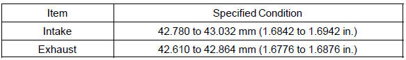
3MZ−FE
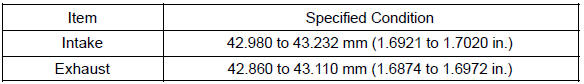
If the cam lobe height is less than the minimum, replace the camshaft.
c. Inspect the camshaft journals.
1. Using a micrometer, measure the journal diameter.
Journal diameter: 26.959 to 26.975 mm (1.0614 to 1.0620 in.)
If the journal diameter is not as specified, check the oil clearance.
55. INSPECT CYLINDER HEAD SET BOLT
a. Using a vernier caliper, measure the tension portion diameter of the bolt.
Specified outside diameter: 8.75 to 9.05 mm (0.3445 to 0.3563 in.)
If the diameter is less than the minimum, replace the bolt.
 Inspect cylinder head set bolt
56. INSTALL SPARK PLUG TUBE GASKET
-
Using SST and a hammer, tap in a new gasket until its surface is flush with the upper edge of the cylinder head cover.
SST 09950−60010 (09951−00430), 09950−70010 (09951−07100)
-
Return the ventilation plate tab to its original position.
-
Apply a light coat of MP grease to the gasket lip.
Install spark plug tube gasket
57. INSTALL ENGINE REAR OIL SEAL
a. Using SST and a hammer, tap in a new oil seal until its surface is flush with the rear oil seal retainer edge.
SST 09223−15030, 09950−70010 (09951−07100)
NOTICE:
-
Be careful not to tap the oil seal at an angle.
-
Keep the gap between the rear oil seal retainer edge and the oil seal free of foreign matter.
b. Apply MP grease to the oil seal lip.
58. INSTALL ENGINE REAR OIL SEAL RETAINER
a. Remove any old packing material from the contact surface.
b. Apply a continuous bead of seal packing (diameter 2 to 3 mm (0.08 to 0.12 in.)) as shown in the illustration.
Seal packing: Part No. 08826−00080 or equivalent
NOTICE:
-
Remove any oil from the contact surface.
Install the oil seal retainer within 3 minutes after applying seal packing.
-
Do not expose the seal to engine oil for at least 2 hours after installing.
c. Install the oil seal retainer. Tighten the 6 bolts uniformly.
Torque: 8.0 N·m (82 kgf·cm, 71 in.·lbf)
59. INSTALL OIL PUMP SEAL
Engine (2AZ−FE) (From July, 2003)
Timing gear case or timing chain case oil seal (2AZ−FE)(From July, 2003)
Engine rear oil seal (2AZ−FE)(From July, 2003)
Cylinder head assy (2AZ−FE) (From July, 2003)
Cylinder block assy (2AZ−FE)(From July, 2003)
Engine (1MZ−FE/3MZ−FE)
Drive belt (1MZ−FE/3MZ−FE)
Valve clearance (1MZ−FE/3MZ−FE)
Partial engine assy (1MZ−FE/3MZ−FE)
Partial engine assy (2AZ−FE)(From July, 2003)
Partial engine assy (1MZ−FE/3MZ−FE)
Timing belt (1MZ−FE/3MZ−FE)
Camshaft (RH BANK) (1MZ−FE/3MZ−FE)
Camshaft (LH BANK) (1MZ−FE/3MZ−FE)
Cylinder head gasket (1MZ−FE/3MZ−FE)
Cylinder head gasket No.2 (1MZ−FE/3MZ−FE)
Oil pump seal (1MZ−FE/3MZ−FE)
Engine rear oil seal (1MZ−FE/3MZ−FE)
Cylinder head assy (1MZ−FE/3MZ−FE)
Cylinder block assy (1MZ−FE/3MZ−FE)
Partial engine assy (2AZ−FE)(From July, 2003)
Drive belt (2AZ−FE)(From July, 2003)
Valve clearance (2AZ−FE)
Chain (2AZ−FE)(From July, 2003)
Camshaft (2AZ−FE)(From July, 2003)
Cylinder head gasket (2AZ−FE)(From July, 2003)
Toyota Camry XV30 (2002–2006) Service Manual
- Introduction
- Audio & visual system
- Automatic transmission / trans
- Brake
- Clutch
- Communication system
- Cooling
- Cruise control
- Drive shaft / propeller shaft
- Emission control
- Engine control system
- Engine hood/door
- Engine mechanical
- Exhaust
- Exterior/interior trim
- Front suspension
- Fuel
- Heater & air conditioner
- Ignition
- Instrument panel/meter
- Intake
- Lighting
- Lubrication
- Manual transmission/transaxle
- Parking brake
- Power steering
- Rear suspension
- Seat
- Service specifications
- Sliding roof/convertible
- Starting & charging
- Steering column
- Supplemental restraint system
- Theft deterrent & door lock
- Tire & wheel
- Windshield/windowglass/mirror
- Wiper & washer
- Wiring
Categories
