 Toyota Camry XV30 (2002–2006) Service ManualEngine mechanical
Timing belt (1MZ−FE/3MZ−FE)
Timing belt (1MZ−FE/3MZ−FE)
REPLACEMENT
-
REMOVE FRONT WHEEL RH
-
REMOVE FRONT FENDER APRON SEAL RH
-
REMOVE V (COOLER COMPRESSOR TO CRANKSHAFT PULLEY) BELT No.1
-
REMOVE VANE PUMP V BELT
-
REMOVE ENGINE MOVING CONTROL ROD
-
REMOVE ENGINE MOUNTING STAY No.2 RH
-
REMOVE GENERATOR BRACKET No.2
-
REMOVE CRANKSHAFT PULLEY
a. Using SST, loosen the pulley bolt.
SST 09213−54015 (91651−60855), 09330−00021
b. Using SST and the pulley bolt, remove the pulley.
SST 09950−50013 (09951−05010, 09952−05010, 09953−05010, 09954−05030)
NOTICE: Before using SST, apply lubricating oil on the threads and tip of the center bolt 100.
-
REMOVE TIMING BELT No.1 COVER
-
REMOVE TIMING BELT No.2 COVER
-
Disconnect the engine wire protector clamps from the timing belt No. 3 cover.
-
Remove the 5 bolts and timing belt cover.
Remove timing belt No.2 Cover
-
REMOVE ENGINE MOUNTING BRACKET RH
-
REMOVE TIMING BELT GUIDE No.2
-
REMOVE TIMING BELT
a. Set the No. 1 cylinder to TDC/compression.
-
Temporarily install the crankshaft pulley bolt with the washer to the crankshaft.
-
Turn the crankshaft clockwise, and align the timing marks of the crankshaft timing pulley and oil pump body.
-
Check that the timing marks of the camshaft timing pulleys and No. 3 timing belt cover are aligned. If not, turn the crankshaft 1 revolution (360 ).
-
Remove the crankshaft pulley bolt.
b. If reusing the timing belt, check that there are 4 installation marks on the timing belt as shown in the illustration.
1. If the installation marks have disappeared, put new installation marks on the timing belt before removing.

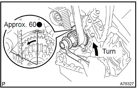
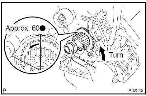
c. Set the No. 1 cylinder to approximately 60 BTDC/compression.
1. Turn the crankshaft counterclockwise by approximately 60 .
NOTICE: With timing belt removed: The crankshaft pulley must be at the correct angle to avoid damage in later steps. If the crankshaft pulley is at the wrong angle and then the camshaft timing pulley and the camshaft are removed, the piston head and valve head may come in contact and be damaged.
d. Remove the timing belt tensioner.
NOTICE: Do not reinstall the tensioner with its plunger extended.
e. Remove the timing belt in this order.

14. INSTALL TIMING BELT
NOTICE:
-
Do not bend, twist or turn the timing belt inside out.
-
Do not allow the timing belt to come into contact with oil, water or steam.
-
Do not utilize timing belt tension when instaling the mounting bolt of the camshaft timing pulley.
a. Remove any oil or water on the pulleys, and keep them clean.
NOTICE:
-
If there is a trace of water and/or oil on the timing belt, repair the leakage and install a new timing belt.
-
Only wipe the pulleys. Do not use cleaning agents on the pulleys.
b. Inspect the idler pulleys.
-
Check that the idler pulleys turn smoothly.
-
Visually check the sealed portion of the idler pulleys for oil leakage.
c. Inspect the water pump.
-
Turn the pulley, and check that the water pump bearing moves smoothly without any noise.
-
Visually check the drain hole for coolant leakage.
d. Temporarily install the crankshaft pulley bolt and washer to the crankshaft.
e. Turn the crankshaft counterclockwise by approximately 60 .
NOTICE: To prevent the piston head and the valve head from colliding, set the crankshaft pulley at approximately 60 BTDC/ compression position.
f. Using SST, turn the timing pulleys, and align the timing marks of the timing pulleys with the No. 3 timing belt cover.
SST 09960−10010 (09962−01000, 09963−01000)
g. Turn the crankshaft, and align the timing mark of the crankshaft timing pulley with the oil pump body.
-
Face the front mark on the timing belt forward.
-
Align the installation mark on the timing belt with the timing mark of the crankshaft timing pulley.
-
Align the installation marks on the timing belt with the timing marks of the camshaft timing pulleys.
k. Install the timing belt in this order.

15. INSTALL TIMING BELT TENSIONER ASSY
-
Set the timing belt tensioner uprightly on the press.
-
Slowly press in the push rod.
NOTICE: Do not apply pressure of more than 9.8 kN (1,000 kgf, 2,205 lbf) to the rod.
-
Align the holes of the push rod and housing, pass a 1.5 mm hexagon wrench through the holes to keep the setting position of the push rod.
-
Release the push rod.
e. Temporarily install the tensioner with the 2 bolts.
Torque: 27 N·m (280 kgf·cm, 20 ft·lbf)
NOTICE: Install the tensioner’s bolts uniformly and evenly. Installing the tensioner at an angle may cause it to malfunction.
-
Remove the 1.5 mm hexagon wrench from the tensioner.
-
Turn the crankshaft 2 revolutions slowly and align the timing mark of the crankshaft timing pulley with the oil pump body.
NOTICE: Always turn the crankshaft clockwise.
h. Check that the timing marks of the RH and LH timing pulleys are aligned with the timing marks of the No. 3 timing belt cover as shown in the illustration.
If the marks do not align, remove the timing belt and reinstall it.
i. Remove the crankshaft pulley bolt.
16. INSTALL TIMING BELT GUIDE No.2
a. Install the timing belt guide, facing the cup side toward the engine front.
Install timing belt guide No.2
-
INSTALL ENGINE MOUNTING BRACKET RH Torque: 28 N·m (286 kgf·cm, 21 ft·lbf)
-
INSTALL TIMING BELT No.2 COVER
a. Visually check for cracks and breaks on the gasket of the timing belt cover.
HINT: If it is judged that water is entering at the visual check, replace the timing belt cover.
b. Install the timing belt cover.
Torque: 8.5 N·m (87 kgf·cm, 76 in.·lbf)
19. INSTALL TIMING BELT No.1 COVER
a. Visually check for cracks and breaks on the gasket of the timing belt cover.
HINT: If there is a trace that water is entering at the visual check, replace the timing belt cover.
-
Install the timing belt cover.
Torque: 8.5 N·m (87 kgf·cm, 75 in.·lbf)
-
Install the engine wire protector cover to the timing belt No. 3 cover.
20. INSTALL CRANKSHAFT PULLEY
-
Align the pulley set key with the key groove of the pulley, and slide on the pulley.
-
Using SST, install the pulley bolt.
SST 09213−54015 (91651−60855), 09330−00021
Torque: 220 N·m (2250 kgf·cm, 162 ft·lbf)
Install crankshaft pulley
-
INSTALL GENERATOR BRACKET No.2 Torque: 28 N·m (286 kgf·cm, 21 ft·lbf)
-
INSTALL ENGINE MOUNTING STAY No.2 RH
-
INSTALL ENGINE MOVING CONTROL ROD
-
INSTALL VANE PUMP V BELT
-
INSTALL V (COOLER COMPRESSOR TO CRANKSHAFT PULLEY) BELT No.1
-
INSPECT DRIVE BELT TENSION
-
INSTALL FRONT WHEEL RH
Engine (2AZ−FE) (From July, 2003)
Timing gear case or timing chain case oil seal (2AZ−FE)(From July, 2003)
Engine rear oil seal (2AZ−FE)(From July, 2003)
Cylinder head assy (2AZ−FE) (From July, 2003)
Cylinder block assy (2AZ−FE)(From July, 2003)
Engine (1MZ−FE/3MZ−FE)
Drive belt (1MZ−FE/3MZ−FE)
Valve clearance (1MZ−FE/3MZ−FE)
Partial engine assy (1MZ−FE/3MZ−FE)
Partial engine assy (2AZ−FE)(From July, 2003)
Partial engine assy (1MZ−FE/3MZ−FE)
Timing belt (1MZ−FE/3MZ−FE)
Camshaft (RH BANK) (1MZ−FE/3MZ−FE)
Camshaft (LH BANK) (1MZ−FE/3MZ−FE)
Cylinder head gasket (1MZ−FE/3MZ−FE)
Cylinder head gasket No.2 (1MZ−FE/3MZ−FE)
Oil pump seal (1MZ−FE/3MZ−FE)
Engine rear oil seal (1MZ−FE/3MZ−FE)
Cylinder head assy (1MZ−FE/3MZ−FE)
Cylinder block assy (1MZ−FE/3MZ−FE)
Partial engine assy (2AZ−FE)(From July, 2003)
Drive belt (2AZ−FE)(From July, 2003)
Valve clearance (2AZ−FE)
Chain (2AZ−FE)(From July, 2003)
Camshaft (2AZ−FE)(From July, 2003)
Cylinder head gasket (2AZ−FE)(From July, 2003)
Toyota Camry XV30 (2002–2006) Service Manual
- Introduction
- Audio & visual system
- Automatic transmission / trans
- Brake
- Clutch
- Communication system
- Cooling
- Cruise control
- Drive shaft / propeller shaft
- Emission control
- Engine control system
- Engine hood/door
- Engine mechanical
- Exhaust
- Exterior/interior trim
- Front suspension
- Fuel
- Heater & air conditioner
- Ignition
- Instrument panel/meter
- Intake
- Lighting
- Lubrication
- Manual transmission/transaxle
- Parking brake
- Power steering
- Rear suspension
- Seat
- Service specifications
- Sliding roof/convertible
- Starting & charging
- Steering column
- Supplemental restraint system
- Theft deterrent & door lock
- Tire & wheel
- Windshield/windowglass/mirror
- Wiper & washer
- Wiring
Categories
