 Toyota Camry XV30 (2002–2006) Service ManualEngine mechanical
Chain (2AZ−FE)(From July, 2003)
Chain (2AZ−FE)(From July, 2003)
REPLACEMENT
-
REMOVE HOOD SUB−ASSY
-
REMOVE FRONT WHEEL RH
-
REMOVE ENGINE UNDER COVER LH
-
REMOVE ENGINE UNDER COVER RH
-
REMOVE FRONT FENDER APRON SEAL RH
-
DRAIN ENGINE OIL
a. Install a new gasket and the drain plug after draining engine oil.
Torque: 25 N·m (255 kgf·cm, 18 ft·lbf)
-
REMOVE EXHAUST PIPE ASSY FRONT
-
REMOVE ENGINE MOVING CONTROL ROD W/BRACKET
a. Remove the 3 bolts and control rod.
-
REMOVE ENGINE MOUNTING STAY No.2 RH
-
REMOVE ENGINE MOUNTING BRACKET No.2 RH
-
REMOVE FAN AND GENERATOR V BELT
-
REMOVE ENGINE COVER SUB−ASSY No.1
-
DISCONNECT ENGINE WIRE
-
REMOVE GENERATOR ASSY
-
REMOVE VANE PUMP ASSY
NOTICE: Do not disconnect the hose.
-
REMOVE IGNITION COIL ASSY
-
DISCONNECT VENTILATION HOSE
-
DISCONNECT VENTILATION HOSE No.2
-
REMOVE CYLINDER HEAD COVER SUB−ASSY
-
Remove the bolt and disconnect the engine wire harness clamp.
-
Remove the 8 bolts and 2 nuts, and disconnect the cylinder head cover
 Remove cylinder head cover sub-assy
-
SET No. 1 CYLINDER TO TDC/COMPRESSION
-
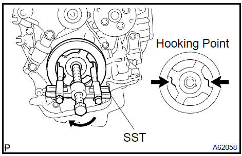
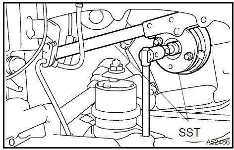
REMOVE CRANKSHAFT PULLEY
a. TMC made: Remove the crankshaft pulley.
1. Using SST, fix the pulley and loosen the bolt.
SST 09213−54015 (91651−60855), 09330−00021
2. Using SST, remove the bolt and pulley.
SST 09950−50013 (09951−05010, 09952−05010, 09953−05020, 09954−05021)
b. TMMK made: Remove the crankshaft pulley.
1. Using SST, fix the pulley and remove the bolt.
SST 09960−10010 (09962−01000, 09963−01000)
2. Using SST, remove the crankshaft pulley.
SST 09950−40011 (09951−04010, 09952−04010, 09953−04030, 09954−04010, 09955−04041, 09957−04010, 91111−51014)
-
REMOVE CRANKSHAFT POSITION
-
REMOVE OIL PAN SUB−ASSY
a. Remove the 12 bolts and 2 nuts.
b. Insert the blade of SST between the crankcase and oil pan. Cut through the sealer and remove the oil pan.
SST 09032−00100
NOTICE: Be careful not to damage the contact surface of the cylinder block and oil pan.
24. REMOVE CHAIN TENSIONER ASSY No.1
a. Remove the 2 nuts, tensioner and gasket.
NOTICE: Do not revolve the crankshaft without the tensioner.
25. REMOVE V−RIBBED BELT TENSIONER ASSY
a. Remove the bolt, nut and tensioner.
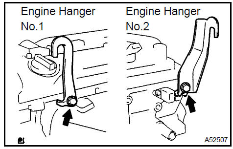
26. INSTALL ENGINE HANGER No.1
a. Install the engine hanger No. 1 and No. 2 with the bolts as shown in the illustration.
Parts No.:
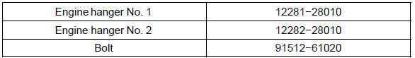
Torque: 38 N·m (387 kgf·cm, 28 ft·lbf)
27. REMOVE ENGINE MOUNTING INSULATOR
a. Attach the engine chain hoist to the engine hangers.
CAUTION: Do not attempt to hang the engine by hooking the chain to any other part.
b. Remove the bolt and disconnect the engine mounting insulator FR.
c. M/T: Remove the bolt and disconnect the engine lateral control rod.
d. Remove the bolt and disconnect the steering gear return hose clamp from the frame.
e. Remove the 4 nuts from the engine mounting insulator RH.
f. Raise the engine and remove the engine mounting insulator RH.
28. REMOVE ENGINE MOUNTING BRACKET RH
a. Remove the 3 bolts and engine mounting bracket.
29. REMOVE TIMING CHAIN OR BELT COVER SUB−ASSY
-
Remove the stud bolt for the drive belt tensioner from the cylinder block.
-
Remove the 14 bolts and 2 nuts.
-
Pry out the timing chain cover with a screwdriver.
NOTICE: Be careful not to damage the contact surfaces of the timing chain cover, cylinder block and cylinder head.
-
REMOVE CRANKSHAFT POSITION PLATE No.1
-
REMOVE CHAIN TENSIONER SLIPPER
-
REMOVE CHAIN VIBRATION DAMPER No.1
-
REMOVE CHAIN SUB−ASSY
-
REMOVE CRANKSHAFT TIMING GEAR OR SPROCKET
-
REMOVE No.2 CHAIN SUB−ASSY
a. Turn the crankshaft counterclockwise by 90 , and align an adjusting hole of the oil pump driven sprocket with the groove of the oil pump.
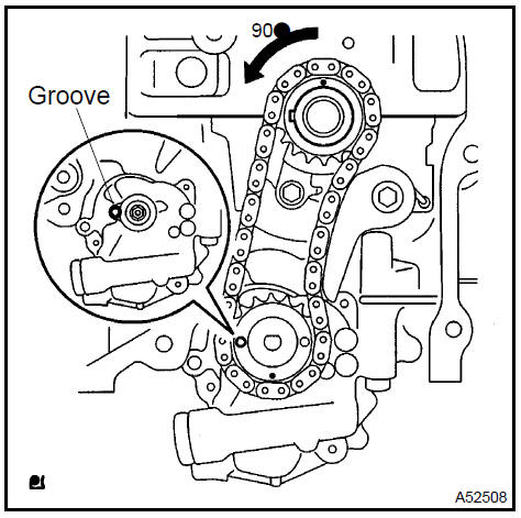
b. Put a bar (ϕ 4 mm) in the adjusting hole of the oil pump driven sprocket to temporarily lock the sprocket in position.
Remove the nut.
-
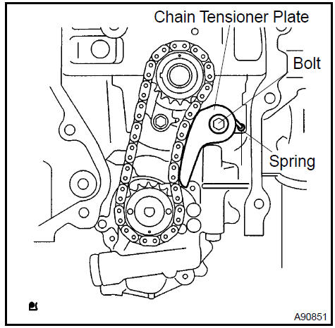
Remove the bolt, chain tensioner plate and spring.
-
Remove the chain tensioner, oil pump driven sprocket and chain.
36. INSTALL No.2 CHAIN SUB−ASSY
-
Set the crankshaft key into the left horizontal position.
-
Turn the cutout of the drive shaft to the top.
-
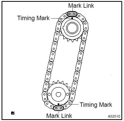
Align the mark links (yellow colored links) with the timing marks of the sprocket as shown in the illustration.
-
Insert the sprockets with chain to the crankshaft and oil pump shaft.
-
Temporarily tighten the oil pump driven sprocket with the nut.
f Insert the damper spring into the adjusting hole, and install the chain tensioner plate with the nut.
Torque: 12 N·m (122 kgf·cm, 9 ft·lbf)
-
Align the adjusting hole of the oil pump driven sprocket with the groove of the oil pump.
-
Put a bar (ϕ 4 mm) in the adjusting hole of the oil pump driven sprocket to temporarily lock the sprocket in position.
Install the nut.
Torque: 30 N·m (301 kgf·cm, 22 ft·lbf)
i. Rotate the crankshaft counterclockwise by 90 , and align the crankshaft key to the top.
-
INSTALL CHAIN VIBRATION DAMPER No.1 Torque: 9.0 N·m (92 kgf·cm, 80 in.·lbf)
-
INSTALL CHAIN SUB−ASSY
a. Set the No.1 cylinder to TDC/compression.
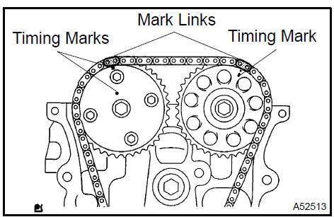
1. Align the timing marks of the camshaft timing sprockets and bearing caps (No. 1 and No. 2).
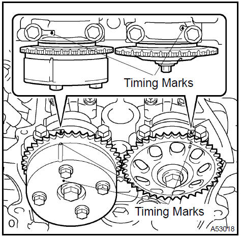
2. Using the crankshaft pulley bolt, turn the crankshaft and set the set key on the crankshaft upward.
b. Align the mark link (gold or orange colored link) with the timing mark of the crankshaft timing sprocket.
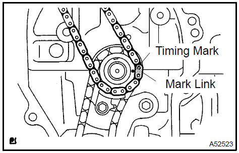
c. Using SST, tap in the sprocket.
SST 09309−37010
d. Align the mark links (gold or yellow colored links) with the timing marks of the camshaft timing gear and camshaft timing sprocket. Install the chain.
-
INSTALL CHAIN TENSIONER SLIPPER Torque: 19 N·m (194 kgf·cm, 14 ft·lbf)
-
INSTALL CRANKSHAFT POSITION PLATE No.1
a. Install the plate with the F mark facing forward.
41. INSTALL TIMING CHAIN OR BELT COVER SUB−ASSY
NOTICE:
- Remove any oil from the contact surface.
- Install the chain cover within 3 minutes after applying seal packing.
- Do not start the engine for at least 2 hours after installing.
- Remove any old packing (FIPG) material and be careful not to drop any oil on the contact surfaces of the timing chain cover, cylinder head and cylinder block.
- Apply seal packing in a continuous bead (diameter: 2 mm
(0.099 in.)) as shown in the illustration.
Seal packing: Part No. 08826−00080 or equivalent
c. Apply seal packing in a continuous bead (diameter: 3 to 4 mm (0.12 to 0.16 in.)) as shown in the illustration.
Seal packing: Part No. 08826−00080 or equivalent
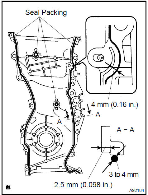
- Install the timing chain cover with the 14 bolts and 2 nuts.
Torque:
9.0 N·m (92 kgf·cm, 80 ft·lbf) for bolt A 21 N·m (214 kgf·cm, 15 ft·lbf) for bolt B 43 N·m (438 kgf·cm, 32 ft·lbf) for bolt C 9.0 N·m (92 kgf·cm, 80 in.·lbf) for nut - Install the stud bolt to the drive belt tensioner.
Torque: 10 N·m (102 kgf·cm, 7 ft·lbf)
42. INSTALL V−RIBBED BELT TENSIONER ASSY
a. Install the tensioner with the bolt and nut.
Torque: 59.5 N·m (607 kgf·cm, 44 ft·lbf)
 Install V-Ribbed belt tensioner assy
43. INSTALL ENGINE MOUNTING BRACKET RH
a. Install the engine mounting bracket with the 3 bolts.
Torque: 54 N·m (551 kgf·cm, 40 ft·lb
f)
 Install engine mounting bracket RH
44. INSTALL ENGINE MOUNTING INSULATOR
- Raise the engine and install the engine mounting insulator RH.
- Install the engine mounting insulator RH with the 4 nuts.
Torque:
95 N·m (969 kgf·cm, 70 ft·lbf) for bolt A 87 N·m (888 kgf·cm, 64 ft·lbf) for bolt B
c. Install the steering gear return hose clamp to the frame with the bolt.
Torque: 8.0 N·m (80 kgf·cm, 69 in.·lbf)
d. Install the engine mounting insulator FR with the bolt.
Torque: 87 N·m (888 kgf·cm, 64 ft·lbf)
e. M/T: Install the engine lateral control rod with the bolt.
Torque: 89 N·m (910 kgf·cm, 66 ft·lbf)
45. INSTALL OIL PAN SUB−ASSY
NOTICE:
- Remove any oil from the contact surface.
- Install the oil pan within 3 minutes after applying seal packing.
- Do not start the engine for at least 2 hours after installing.
- Remove any old packing (FIPG) material and be careful not to drop any oil on the contact surface of the cylinder block and oil pan.
- Apply seal packing in a continuous bead (diameter: 3 to
4 mm (0.12 to 0.16 in.)) as shown in the illustration, and
install the oil pan.
Seal packing: Part No. 08826−00080 or equivalent
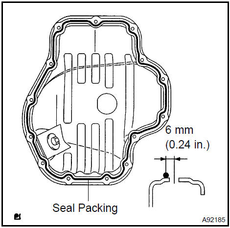
c. Install the oil pan with the 12 bolts and 2 nuts.
Torque: 9.0 N·m (92 kgf·cm, 80 in.·lbf)
- INSTALL CHAIN TENSIONER ASSY No.1
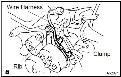
- INSTALL CRANKSHAFT POSITION SENSOR
- Install the bolt and sensor.
Torque: 9.0 N·m (92 kgf·cm, 80 in.·lbf)
- Confirm that the wire harness of the sensor is placed as shown in the illustration.
 Install crankshaft position sensor
48. INSTALL CRANKSHAFT PULLEY
a. TMC made: Install the crankshaft pulley.
- Align the pulley set key with the key groove of the pulley, and side on the pulley.
- Using SST, install the pulley bolt.
SST 09213−54015 (91651−60855), 09330−00021 Torque: 170 N·m (1,733 kgf·cm, 125 ft lbf)
b. TMMK made: Install the crankshaft pulley.
- Align the pulley set key with the key groove of the
pulley, and side on the pulley.
SST 09960−10010 (09962−01000, 09963−01000)
- Using SST, install the pulley bolt.
Torque: 170 N·m (1,733 kgf·cm, 125 ft lbf)
c. Turn the crankshaft counterclockΩise and disconnect the plunger knock pin from the hook.
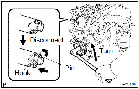
d. Turn the crankshaft clockΩise and check that the slipper is pushed by the plunger.
- INSTALL CYLINDER HEAD COVER SUB−ASSY
- INSTALL IGNITION COIL ASSY Torque: 19 N·m (194 kgf·cm, 14 ft·lbf)
- INSTALL VANE PUMP ASSY
- INSTALL GENERATOR ASSY
- INSTALL ENGINE WIRE
- INSTALL FAN AND GENERATOR V BELT
- INSTALL ENGINE MOUNTING BRACKET No.2 RH Torque: 52 N·m (531 kgf·cm, 38 ft·lbf)
- INSTALL ENGINE MOUNTING STAY No.2 RH Torque: 64 N·m (653 kgf·cm, 47 ft·lbf)
- INSTALL ENGINE MOVING CONTROL ROD W/BRACKET
a. Install the engine mounting control rod with the 3 bolts.
Torque: 64 N·m (653 kgf·cm, 47 ft·lbf)
 Install engine moving control rod W/bracket
- INSTALL EXHAUST PIPE ASSY FRONT
- INSTALL FRONT WHEEL RH
- INSTALL HOOD SUB−ASSY Torque: 13 N·m (133 kgf·cm, 10 ft·lbf)
- ADD ENGINE OIL
- INSPECT CHECK FOR ENGINE OIL LEAKS
Engine (2AZ−FE) (From July, 2003)
Timing gear case or timing chain case oil seal (2AZ−FE)(From July, 2003)
Engine rear oil seal (2AZ−FE)(From July, 2003)
Cylinder head assy (2AZ−FE) (From July, 2003)
Cylinder block assy (2AZ−FE)(From July, 2003)
Engine (1MZ−FE/3MZ−FE)
Drive belt (1MZ−FE/3MZ−FE)
Valve clearance (1MZ−FE/3MZ−FE)
Partial engine assy (1MZ−FE/3MZ−FE)
Partial engine assy (2AZ−FE)(From July, 2003)
Partial engine assy (1MZ−FE/3MZ−FE)
Timing belt (1MZ−FE/3MZ−FE)
Camshaft (RH BANK) (1MZ−FE/3MZ−FE)
Camshaft (LH BANK) (1MZ−FE/3MZ−FE)
Cylinder head gasket (1MZ−FE/3MZ−FE)
Cylinder head gasket No.2 (1MZ−FE/3MZ−FE)
Oil pump seal (1MZ−FE/3MZ−FE)
Engine rear oil seal (1MZ−FE/3MZ−FE)
Cylinder head assy (1MZ−FE/3MZ−FE)
Cylinder block assy (1MZ−FE/3MZ−FE)
Partial engine assy (2AZ−FE)(From July, 2003)
Drive belt (2AZ−FE)(From July, 2003)
Valve clearance (2AZ−FE)
Chain (2AZ−FE)(From July, 2003)
Camshaft (2AZ−FE)(From July, 2003)
Cylinder head gasket (2AZ−FE)(From July, 2003)
Toyota Camry XV30 (2002–2006) Service Manual
- Introduction
- Audio & visual system
- Automatic transmission / trans
- Brake
- Clutch
- Communication system
- Cooling
- Cruise control
- Drive shaft / propeller shaft
- Emission control
- Engine control system
- Engine hood/door
- Engine mechanical
- Exhaust
- Exterior/interior trim
- Front suspension
- Fuel
- Heater & air conditioner
- Ignition
- Instrument panel/meter
- Intake
- Lighting
- Lubrication
- Manual transmission/transaxle
- Parking brake
- Power steering
- Rear suspension
- Seat
- Service specifications
- Sliding roof/convertible
- Starting & charging
- Steering column
- Supplemental restraint system
- Theft deterrent & door lock
- Tire & wheel
- Windshield/windowglass/mirror
- Wiper & washer
- Wiring
Categories
