 Toyota Camry XV30 (2002–2006) Service ManualEngine mechanical
Valve clearance (1MZ−FE/3MZ−FE)
Valve clearance (1MZ−FE/3MZ−FE)
ADJUSTMENT
-
DRAIN ENGINE COOLANT
-
REMOVE FRONT FENDER APRON SEAL RH
-
REMOVE V−BANK COVER SUB−ASSY
-
Using a socket hexagon wrench 5, remove the 3 nuts.
-
Remove the V−bank cover.
Remove V-bank cover sub-assy
-
REMOVE RADIATOR HOSE INLET
-
REMOVE FRONT SUSPENSION UPPER BRACE CENTER (W/ FRONT SUSPENSION BRACE UPPER CENTER)
-
REMOVE AIR CLEANER ASSEMBLY WITH HOSE
-
REMOVE EMISSION CONTROL VALVE SET
-
Disconnect the 2 VSV connectors.
-
Remove the wire harness clamp.
-
Disconnect the fuel vapor feed hose No. 1.
-
Disconnect the fuel vapor feed hose No. 2.
-
Disconnect the 2 vacuum hoses.
-
Remove the clamp.
-
Remove the 2 nuts and the emission control valve set.
8. REMOVE INTAKE AIR SURGE TANK
-
Disconnect the throttle motor connector.
-
Disconnect the water by−pass hose No. 3.
-
Disconnect the water by−pass hose No. 2.
-
Disconnect the union to check valve hose.
e. Disconnect the ventilation hose.
f. Remove the 3 nuts and disconnect the pressure feed tube.
-
Remove the 2 bolts and engine hanger No. 1.
-
Remove the 2 bolts and surge tank stay No. 1.
-
Remove the 2 bolts and surge tank stay No. 2.
-
Using a socket hexagon wrench 8, remove the 4 bolts.
-
Remove the 2 nuts, emission control valve bracket and intake air surge tank.
-
Remove the gasket from the intake air surge tank.
-
REMOVE IGNITION COIL ASSY
-
REMOVE CYLINDER HEAD COVER SUB−ASSY
-
Remove the 2 engine wire harness clamps.
-
Remove the 3 nuts and disconnect the engine wire harness.
-
Remove the 9 bolts and cylinder head cover.
Remove cylinder head cover sub-assy LH
11. REMOVE CYLINDER HEAD COVER SUB−ASSY LH
-
Using an E6 torx socket wrench, remove the 2 bolts and disconnect the engine wire harness protector.
-
Remove the 9 bolts and cylinder head cover.
Remove cylinder head cover sub-assy LH
12. INSPECT VALVE CLEARANCE
-
Turn the crankshaft pulley, and align the timing notch with timing mark 0 of the No. 1 timing belt cover.
-
Check that the valve lifters on the No. 1 timing belt cover (IN and EX) are both loose.
If not, turn the crankshaft 1 revolution (360 ) and align the mark as above.
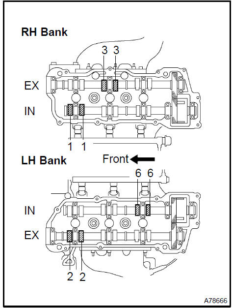
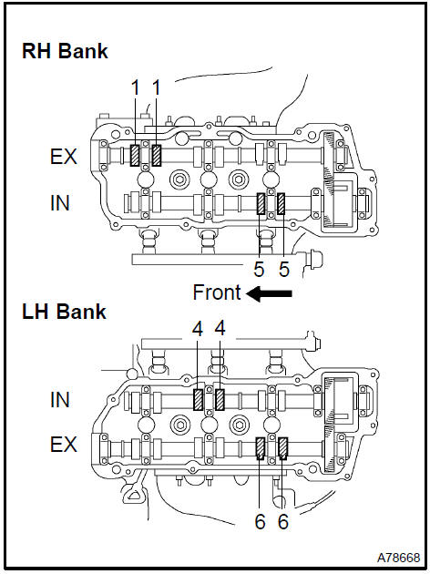
c. Check the valves indicated in the illustration on the left.
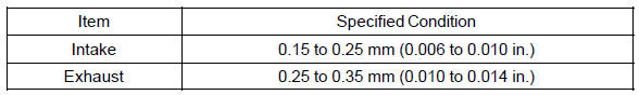
1. Using a feeler gauge, measure the clearance between the valve lifter and camshaft
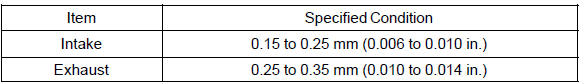
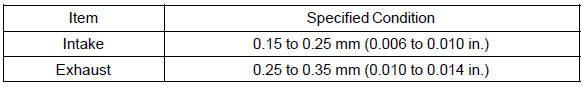
Valve clearance (Cold):
2. Record valve clearance measurements that are out of the specified range. These measurements will be used later to determine the size of the adjustment shim to be installed.
d. Turn the crankshaft 2/3 of a revolution (240 ), and check the valves indicated in the illustration on the left.
1. Using a feeler gauge, measure the clearance between the valve lifter and camshaft.
Valve clearance (Cold):
2. Record valve clearance measurements that are out of the specified range. These measurements will be used later to determine the size of the adjustment shim to be installed.
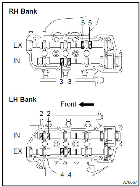
e. Turn the crankshaft 2/3 of a revolution (240 ), and check the valves indicated in the illustration on the left.
1. Using a feeler gauge, measure the clearance between the valve lifter and camshaft.
Valve clearance (Cold):
2. Record valve clearance measurements that are out of the specified range. These measurements will be used later to determine the size of the adjustment shim to be installed.
13. ADJUST VALVE CLEARANCE
-
Turn the camshaft so that the cam lobe faces upward.
-
Turn the valve lifter with a screwdriver so that the notches are perpendicular to the camshaft.
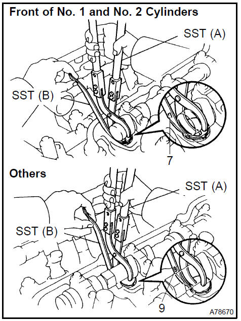
c. Using SST a., press down the valve lifter and place SST b. between the camshaft and valve lifter. Remove SST a..
SST 09248−55040 (09248−05410, 09248−05420)
HINT:
-
Apply SST b. at a slight angle on the side marked with ”9” or ”7” at the position shown in the illustration.
-
When SST b. is inserted too deeply, it will get pinched by the shim. To prevent it from being stuck, insert it gently from the intake side at a slight angle.
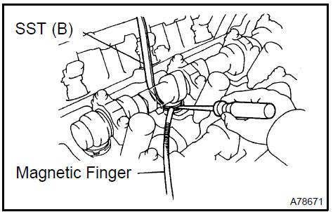
d. Using a small screwdriver and magnetic finger, remove the adjusting shim.
-
Using a micrometer, measure the thickness of the removed shim.
-
Calculate the thickness of a new shim so that the valve clearance comes within the specified value.
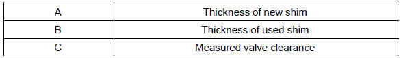
Specified value (Cold): Intake A = B + (C − 0.20 mm (0.0079 in.)) Exhaust A = B + (C − 0.30 mm (0.0118 in.))
g. Select a new shim with a thickness as close as possible to the calculated values.
EXAMPLE (Intake): Measured valve clearance = 0.45 mm (0.0177 in.) 0.45 mm (0.0177 in.) − 0.20 mm (0.0079 in.) = 0.25 mm (0.0098 in.) (Measured − Specification = Excess clearance) Used shim measurement = 2.80 mm (0.1102 in.) 0.25 mm (0.0098 in.) + 2.80 mm (0.1102 in.) = 3.05 mm (0.1201 in.) (Excess clearance + Used shim = Ideal new shim) Closest new shim = 3.05 mm (0.1201 in.) Select No. 12 shim
HINT:
-
Shims are available in 17 sizes in increments of 0.05 mm (0.0020 in.), from 2.50 mm (0.0984 in.) to 3.30 mm (0.1299 in.).
-
Refer to adjusting shim selection chart on the following 2 pages.
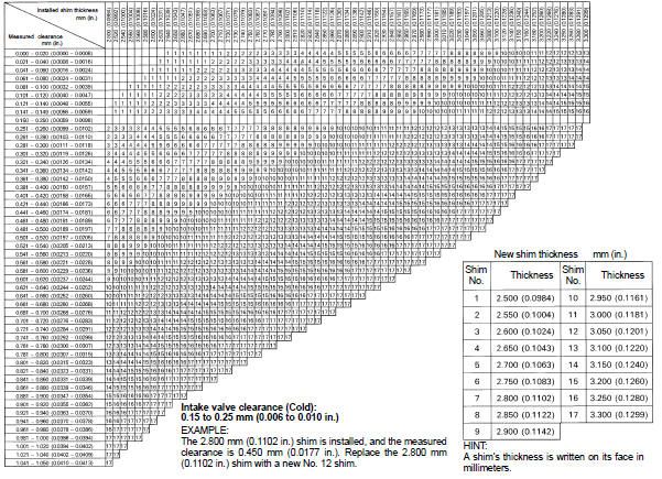 Adjusting Shim Selection Chart (Intake)
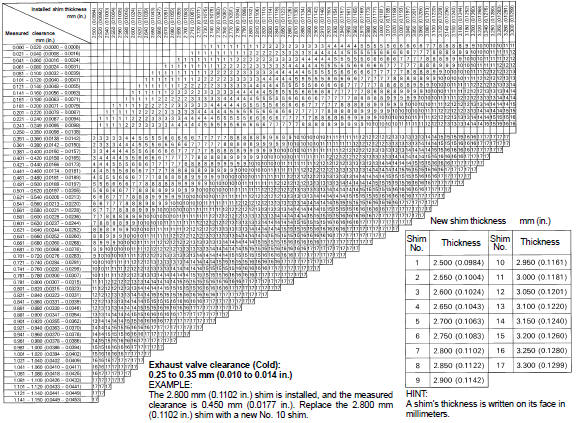 Adjusting Shim Selection Chart (Exhaust)
-
Place a new adjusting shim on the valve lifter with the imprinted number facing down.
-
Press down the valve lifter with SST a., and remove SST b..
SST 09248−55040 (09248−05410, 09248−05420)
-
Recheck the valve clearance.
14. INSTALL CYLINDER HEAD COVER SUB−ASSY
a. Apply seal packing to the cylinder head as shown in the illustration.
Seal packing: Part No. 08826−00080 or equivalent
NOTICE:
-
Remove any oil from the contact surface.
-
Install the cylinder head cover within 3 minutes after applying seal packing.
-
Do not start the engine for at least 2 hours after installing the cylinder head cover.
-
Install the cylinder head cover with the 9 bolts. Tighten the bolts uniformly in several steps.
Torque: 8.0 N·m (80 kgf·cm, 71 in.·lbf)
-
Install the engine wire harness with the 3 nuts.
Torque: 8.4 N·m (85 kgf·cm, 74 in.·lbf)
 Install cylinder head cover sub-assy
15. INSTALL CYLINDER HEAD COVER SUB−ASSY LH
a. Apply seal packing to the cylinder head as shown in the illustration.
Seal packing: Part No. 08826−00080 or equivalent
NOTICE:
-
Remove any oil from the contact surface.
-
Install the cylinder head cover within 3 minutes after applying seal packing.
-
Do not start the engine for at least 2 hours after installing the cylinder head cover.
-
Install the cylinder head cover with the 9 bolts. Tighten the bolts uniformly in several steps.
Torque: 8.0 N·m (80 kgf·cm, 71 in.·lbf)
-
Using an E6 torx) socket wrench, install the engine wire harness protector with the 2 bolts.
 Install cylinder head cover sub-assy LH
-
INSTALL IGNITION COIL ASSY Torque: 8.0 N·m (80 kgf·cm, 71 in.·lbf)
-
INSTALL INTAKE AIR SURGE TANK
-
Install a new gasket to the intake air surge tank.
-
Install the intake air surge tank and emission control valve bracket with the 2 nuts.
Torque: 28 N·m (286 kgf·cm, 21 ft·lbf)
-
Using a socket hexagon wrench 8, tighten the 4 bolts.
Torque: 28 N·m (286 kgf·cm, 21 ft·lbf)
-
Install the surge tank stay No. 2 with the 2 bolts.
Torque: 20 N·m (199 kgf·cm, 15 ft·lbf)
-
Install the surge tank stay No. 1 with the 2 bolts.
Torque: 20 N·m (199 kgf·cm, 15 ft·lbf)
-
Install the engine hanger No. 1 with the 2 bolts.
Torque: 20 N·m (199 kgf·cm, 15 ft·lbf)
-
Install the pressure feed tube with the 3 nuts.
Torque: 7.8 N·m (80 kgf·cm, 69 in.·lbf)
-
Connect the ventilation hose.
-
Connect the union to check valve hose.
-
Connect the water by−pass hose No. 2.
-
Connect the water by−pass hose No. 3.
-
Connect the throttle motor connector.
18. INSTALL EMISSION CONTROL VALVE SET
-
Install the valve set with the 2 nuts.
-
Install the clamp.
-
Connect the 2 vacuum hoses.
-
Connect the fuel vapor feed hose No. 2.
-
Connect the fuel vapor feed hose No. 1.
-
Install the wire harness clamp.
-
Connect the 2 VSV connectors.
-
INSTALL AIR CLEANER ASSEMBLY WITH HOSE
-
INSTALL FRONT SUSPENSION UPPER BRACE CENTER (W/ FRONT SUSPENSION BRACE UPPER CENTER) Torque: 80 N·m (816 kgf·cm, 59 ft.Vlbf)
-
INSTALL RADIATOR HOSE INLET
-
INSTALL V−BANK COVER SUB−ASSY
-
Fit the 2 retainers and install the V−bank cover.
-
Using a socket hexagon wrench 5, tighten the 3 nuts.
Torque: 7.9 N·m (81 kgf·cm, 70 in.·lbf)
-
INSTALL FRONT FENDER APRON SEAL RH
-
ADD ENGINE COOLANT
-
CHECK FOR ENGINE COOLANT LEAKS
Engine (2AZ−FE) (From July, 2003)
Timing gear case or timing chain case oil seal (2AZ−FE)(From July, 2003)
Engine rear oil seal (2AZ−FE)(From July, 2003)
Cylinder head assy (2AZ−FE) (From July, 2003)
Cylinder block assy (2AZ−FE)(From July, 2003)
Engine (1MZ−FE/3MZ−FE)
Drive belt (1MZ−FE/3MZ−FE)
Valve clearance (1MZ−FE/3MZ−FE)
Partial engine assy (1MZ−FE/3MZ−FE)
Partial engine assy (2AZ−FE)(From July, 2003)
Partial engine assy (1MZ−FE/3MZ−FE)
Timing belt (1MZ−FE/3MZ−FE)
Camshaft (RH BANK) (1MZ−FE/3MZ−FE)
Camshaft (LH BANK) (1MZ−FE/3MZ−FE)
Cylinder head gasket (1MZ−FE/3MZ−FE)
Cylinder head gasket No.2 (1MZ−FE/3MZ−FE)
Oil pump seal (1MZ−FE/3MZ−FE)
Engine rear oil seal (1MZ−FE/3MZ−FE)
Cylinder head assy (1MZ−FE/3MZ−FE)
Cylinder block assy (1MZ−FE/3MZ−FE)
Partial engine assy (2AZ−FE)(From July, 2003)
Drive belt (2AZ−FE)(From July, 2003)
Valve clearance (2AZ−FE)
Chain (2AZ−FE)(From July, 2003)
Camshaft (2AZ−FE)(From July, 2003)
Cylinder head gasket (2AZ−FE)(From July, 2003)
Toyota Camry XV30 (2002–2006) Service Manual
- Introduction
- Audio & visual system
- Automatic transmission / trans
- Brake
- Clutch
- Communication system
- Cooling
- Cruise control
- Drive shaft / propeller shaft
- Emission control
- Engine control system
- Engine hood/door
- Engine mechanical
- Exhaust
- Exterior/interior trim
- Front suspension
- Fuel
- Heater & air conditioner
- Ignition
- Instrument panel/meter
- Intake
- Lighting
- Lubrication
- Manual transmission/transaxle
- Parking brake
- Power steering
- Rear suspension
- Seat
- Service specifications
- Sliding roof/convertible
- Starting & charging
- Steering column
- Supplemental restraint system
- Theft deterrent & door lock
- Tire & wheel
- Windshield/windowglass/mirror
- Wiper & washer
- Wiring
Categories
