 Toyota Camry XV30 (2002–2006) Service ManualEngine mechanical
Valve clearance (2AZ−FE)
Valve clearance (2AZ−FE)
ADJUSTMENT
-
REMOVE FRONT WHEEL RH
-
REMOVE FRONT FENDER APRON SEAL RH
-
REMOVE ENGINE COVER SUB−ASSY No.1
-
REMOVE SPARK PLUG
-
DISCONNECT VENTILATION HOSE
-
DISCONNECT VENTILATION HOSE No.2
-
DISCONNECT ENGINE WIRE
-
REMOVE CYLINDER HEAD COVER SUB−ASSY
-
Remove the bolt and disconnect the engine wire harness clamp.
-
Remove the 8 bolts, 2 nuts, cylinder head cover and gasket.
 Remove cylinder head cover sub-assy
9. SET No. 1 CYLINDER TO TDC/COMPRESSION
-
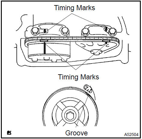
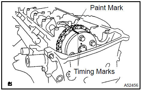
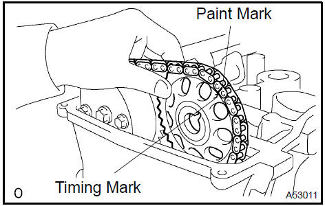
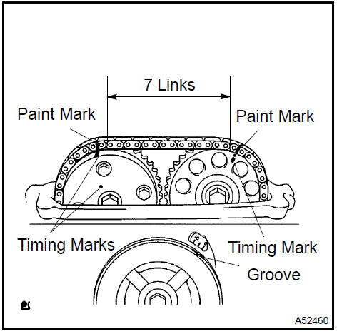
Turn the crankshaft pulley, and align its groove with timing mark 0 of the timing chain cover.
-
Check that the timing marks of the camshaft timing gear and sprocket are aligned with the timing marks of bearing caps No. 1 and No. 2, as shown in the illustration.
 Set No. 1 Cylinder to TDC/compression
10. INSPECT VALVE CLEARANCE
HINT: Inspect and adjust the valve clearance when the engine is cold.
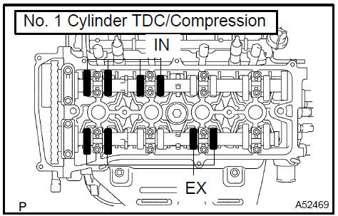
a. Check only the valves indicated on the left.
-
Using a feeler gauge, measure the clearance between each valve lifter and camshaft.
-
Record valve clearance measurements that are out of the specified range. These measurements will be used later to determine the size of the adjustment shim to be installed.
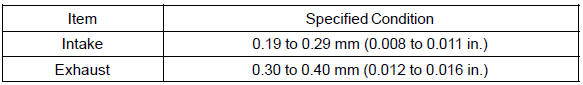
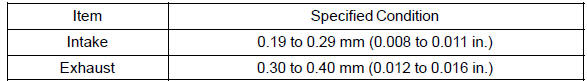
Valve clearance (Cold):
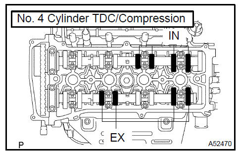
b. Turn the crankshaft clockwise 1 revolution (360 ) and set the No. 4 cylinder to TDC/compression.
c. Check only the valves indicated on the left.
-
Using a feeler gauge, measure the clearance between each valve lifter and camshaft.
-
Record valve clearance measurements that are out of the specified range. These measurements will be used later to determine the size of the adjustment shim to be installed.
Valve clearance (Cold):
11. ADJUST VALVE CLEARANCE
NOTICE: Be sure not to turn the crankshaft without the chain tensioner.
-
Turn the crankshaft clockwise 1 revolution (360 ) and set the No. 1 cylinder to the TDC/compression.
-
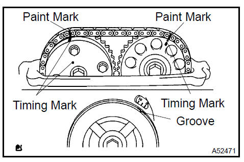
Place paint marks on the timing chain and camshaft timing gear/sprocket
c. Remove the 2 bolts and chain tensioner.
d. Remove the No. 2 camshaft.
1. Fix the camshaft with a wrench and then loosen the sproket bolt.
NOTICE: Be careful not to damage the valve lifter.
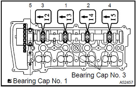
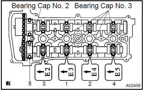
2. Uniformly loosen and remove the No. 2 camshaft’s 10 bearing cap bolts in the sequence shown in the illustration. Then remove the 5 bearing caps.
-
Raise the No. 2 camshaft and remove it. Then remove the sprocket bolt.
-
Remove the camshaft timing sprocket and the timing chain from the No. 2 camshaft.
-
Remove the camshaft timing sprocket from the timing chain.
e. Remove the camshaft.
-
Uniformly loosen and remove the camshaft’s 10 bearing cap bolts in the sequence shown in the illustration.
Then remove the 5 bearing caps.
-
Remove the camshaft.
f. Tie the timing chain with a string.
NOTICE: Be careful not to drop anything inside the timing chain cover.
g. Remove the valve lifters.
h. Adjust the valve clearance.
-
Using a micrometer, measure the thickness of the removed lifter.
-
Calculate the thickness of a new lifter so that the valve clearance comes within the specified value.
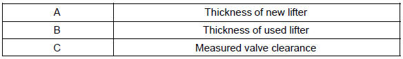
Valve clearance:
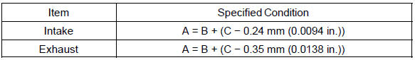
EXAMPLE: (Intake) Measured valve clearance = 0.44 mm (0.0173 in.) 0.44 mm (0.0173 in.) − 0.24 mm (0.0094 in.) = 0.20 mm (0.0079 in.) (Measured − Specification = Excess clearance) Used shim measurement = 5.30 mm (0.2087 in.) 0.20 mm (0.0079 in.) + 5.30 mm (0.2087 in.) = 5.50 mm (0.2165 in.) (Excess clearance + Used shim = Ideal new shim) Closest new shim = 5.50 mm (0.2165 in.) = Shim No. ”50”
3. Select a new lifter with a thickness as close as possible to the calculated values.
HINT:
-
Lifters are available in 35 sizes in increments of 0.020 mm (0.0008 in.), from 5.060 mm (0.1992 in.) to 5.740 mm (0.2260 in.).
-
Refer to valve lifter selection chart on the following 2 pages.
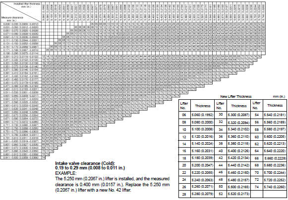 Valve Lifter Selection Chart (Intake)
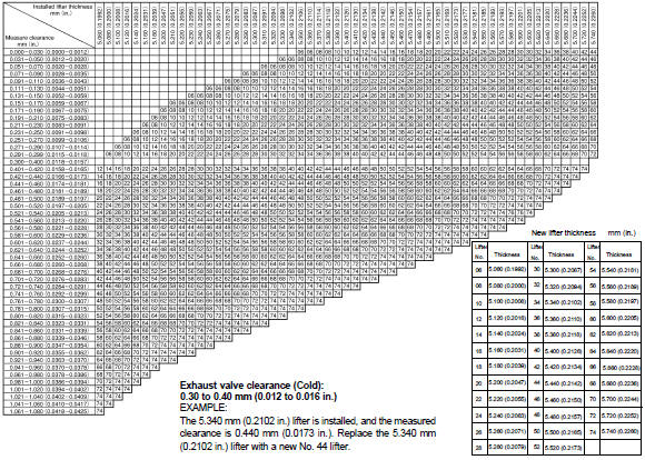 Valve Lifter Selection Chart (Exhaust)
i. Install the camshaft.
1. Install the timing chain on the camshaft timing gear, with the paint mark aligned with the timing marks on the camshaft timing gear.
2. Examine the front marks and numbers of the 5 bearing caps and install them. Then install the 10 bearing cap bolts. Uniformly tighten the bolts in the sequence shown in the illustration.
Torque:
30 N·m (301 kgf·cm, 22 ft·lbf) for bearing cap No. 1
9.0 N·m (92 kgf·cm, 80 in.·lbf) for bearing cap No. 3
j. Install the No. 2 camshaft.
1. Put the No. 2 camshaft on the cylinder head with the paint mark of the chain aligned with the timing mark on the camshaft timing sprocket
2. Raise the No. 2 camshaft and temporarily tighten the sprocket bolt.
3. Examine the front marks and numbers of the 5 bearing caps and install them. Then install the 10 bearing cap bolts. Uniformly tighten the bolts in the sequence shown in the illustration.
Torque:
30 N·m (301 kgf·cm, 22 ft·lbf) for bearing cap No. 2
9.0 N·m (92 kgf·cm, 80 in.·lbf) for bearing cap No. 3
4. Fix the camshaft with a wrench, then tighten the sprocket bolt.
Torque: 54 N·m (551 kgf·cm, 40 ft·lbf)
NOTICE: Be careful not to damage the valve lifter.
k. Check that the timing chain paint marks are aligned with the camshaft timing sprocket timing mark and the camshaft timing gear timing mark. Also check the alignment of the pulley groove and chain cover timing mark 0.
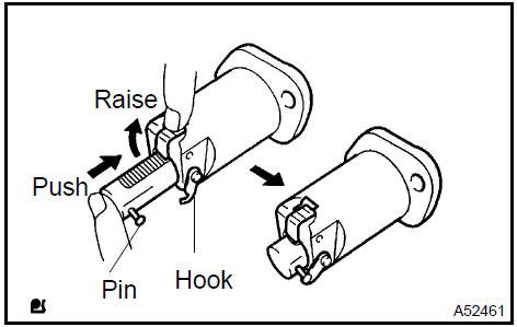
l. Install the chain tensioner.
1. Raise the ratchet pawl, fully push in the plunger and apply the hook to the pin so that the plunger cannot spring out.
2. Install a new gasket and the chain tensioner with the 2 nuts.
Torque: 9.0 N·m (92 kgf·cm, 80 in.·lbf)
NOTICE: When installing the tensioner, set the hook again if the hook releases the plunger.
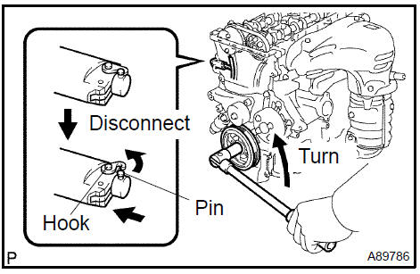
3. Turn the crankshaft counterclockwise, and disconnect the plunger knock pin from the hook.
4. Turn the crankshaft clockwise, and check that the chain tensioner slipper is pushed by the plunger.
12. INSTALL CYLINDER HEAD COVER SUB−ASSY
a. Remove any old packing (FIPG) material.
b. Apply seal packing to the 2 locations shown in the illustration.
Seal packing: Part No. 08826−00080 or equivalent
NOTICE:
-
Remove any oil from the contact surface.
-
Install the cylinder head cover within 5 minutes after applying seal packing.
-
Do not start the engine for at least 2 hours after installing the cylinder head cover.
c. Install the cylinder head cover with the 8 bolts and 2 nuts.
Torque: 11 N·m (110 kgf·cm, 8 ft·lbf)
-
INSTALL SPARK PLUG Torque: 19 N·m (194 kgf·cm, 14 in.·lbf)
-
INSTALL FRONT WHEEL RH
-
INSPECT OIL LEAK
Engine (2AZ−FE) (From July, 2003)
Timing gear case or timing chain case oil seal (2AZ−FE)(From July, 2003)
Engine rear oil seal (2AZ−FE)(From July, 2003)
Cylinder head assy (2AZ−FE) (From July, 2003)
Cylinder block assy (2AZ−FE)(From July, 2003)
Engine (1MZ−FE/3MZ−FE)
Drive belt (1MZ−FE/3MZ−FE)
Valve clearance (1MZ−FE/3MZ−FE)
Partial engine assy (1MZ−FE/3MZ−FE)
Partial engine assy (2AZ−FE)(From July, 2003)
Partial engine assy (1MZ−FE/3MZ−FE)
Timing belt (1MZ−FE/3MZ−FE)
Camshaft (RH BANK) (1MZ−FE/3MZ−FE)
Camshaft (LH BANK) (1MZ−FE/3MZ−FE)
Cylinder head gasket (1MZ−FE/3MZ−FE)
Cylinder head gasket No.2 (1MZ−FE/3MZ−FE)
Oil pump seal (1MZ−FE/3MZ−FE)
Engine rear oil seal (1MZ−FE/3MZ−FE)
Cylinder head assy (1MZ−FE/3MZ−FE)
Cylinder block assy (1MZ−FE/3MZ−FE)
Partial engine assy (2AZ−FE)(From July, 2003)
Drive belt (2AZ−FE)(From July, 2003)
Valve clearance (2AZ−FE)
Chain (2AZ−FE)(From July, 2003)
Camshaft (2AZ−FE)(From July, 2003)
Cylinder head gasket (2AZ−FE)(From July, 2003)
Toyota Camry XV30 (2002–2006) Service Manual
- Introduction
- Audio & visual system
- Automatic transmission / trans
- Brake
- Clutch
- Communication system
- Cooling
- Cruise control
- Drive shaft / propeller shaft
- Emission control
- Engine control system
- Engine hood/door
- Engine mechanical
- Exhaust
- Exterior/interior trim
- Front suspension
- Fuel
- Heater & air conditioner
- Ignition
- Instrument panel/meter
- Intake
- Lighting
- Lubrication
- Manual transmission/transaxle
- Parking brake
- Power steering
- Rear suspension
- Seat
- Service specifications
- Sliding roof/convertible
- Starting & charging
- Steering column
- Supplemental restraint system
- Theft deterrent & door lock
- Tire & wheel
- Windshield/windowglass/mirror
- Wiper & washer
- Wiring
Categories
