 Toyota Camry XV30 (2002–2006) Service ManualEngine mechanical
Engine (1MZ−FE/3MZ−FE)
Engine (1MZ−FE/3MZ−FE)
INSPECTION
-
INSPECT ENGINE COOLANT
-
INSPECT ENGINE OIL
-
INSPECT BATTERY
-
INSPECT AIR CLEANER FILTER ELEMENT SUB−ASSY
-
INSPECT SPARK PLUG
-
INSPECT V−RIBBED BELT
a. Using a belt tension gauge, check the belt tension.
Belt tension gauge:
DENSO BTG−20 (95506−00020)
Borroughs No. BT−33−73F
Drive belt tension:
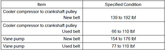
HINT:
-
After installing the drive belt, check that it fits properly in the ribbed grooves. Check with your hand to confirm that the belt has not slipped out of the groove on the bottom of the crankshaft pulley.
-
”New belt” is a belt which has been used less than 5 minutes on a running engine.
-
”Used belt” is a belt which has been used on a running engine for 5 minutes or more.
-
After installing a new belt, run the engine for approximately 5 minutes and then recheck the tension.
7. INSPECT IGNITION TIMING
a. Warm up the engine.
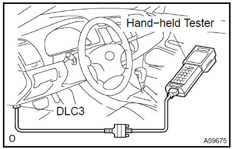
b. When using the hand−held tester: Check the ignition timing.
-
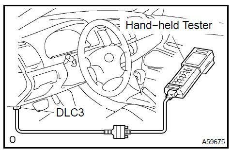
Connect the hand−held tester to the DLC3.
-
Enter DATA LIST MODE on the hand−held tester.
Ignition timing : 8 to 12 BTDC @ idle
HINT: Please refer to the hand−held tester operator’s manual for help on selecting the DATA LIST.
c. When not using the hand−held tester: Check the ignition timing.
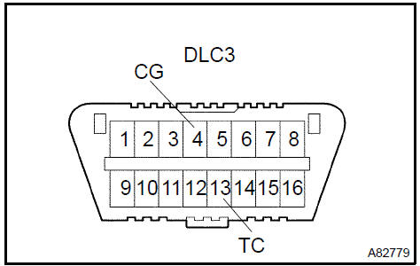
1. Using SST, connect terminals 13 (TC) and 4 (CG) of the DLC3.
NOTICE:
-
Confirm the terminal numbers before connecting them. Connection with a wrong terminal can damage the engine.
-
Turn off all electrical systems before connecting the terminals.
-
Perform this inspection after the cooling fan motor is turned off.
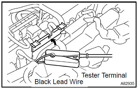
2. Remove the V−bank cover.
-
Pull out the black lead wire harness as shown in the illustration.
-
Connect the tester terminal of the timing light to the engine.
NOTICE: Use a timing light which detects the first signal.
5. Check the ignition timing at idle.
Ignition timing : 8 to 12 BTDC @ idle
NOTICE: When checking the ignition timing, the transmission should be in the neutral position.
HINT: Run the engine at 1,000 to 1,300 rpm for 5 seconds, and then check that the engine rpm returns to idle speed.
-
Disconnect terminals 13 (TC) and 4 (CG) of the DLC3.
-
Check the ignition timing at idle.
Ignition timing : 7 to 24 BTDC @ idle
-
Confirm that the ignition timing moves to the advanced angle side when the engine rpm is increased.
-
Remove the timing light.
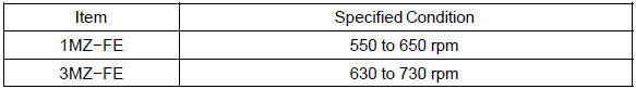
8. INSPECT ENGINE IDLE SPEED
a. Warm up the engine.
b. When using the hand−held tester: Check the idle speed.
-
Connect the hand−held tester to the DLC3.
-
Enter DATA LIST MODE on the hand−held tester.
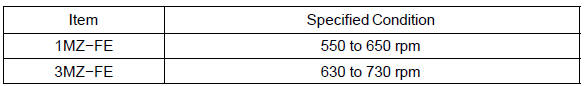
Idle speed:
NOTICE:
-
When checking the idle speed, the transmission should be in the neutral position.
-
Check the idle speed with the cooling fan off.
-
Switch off all accessories and air conditioning before connecting the hand−held tester.
HINT: Please refer to the hand−held tester operator’s manual for further details.
c. When not using the hand−held tester: Check the idle speed.
-
Using SST, connect tachometer test probe to terminal 9 (TAC) of the DLC3.
SST 09843−18030
-
Check the idle speed.
Idle speed:
9. INSPECT COMPRESSION
-
Warm up and stop the engine.
-
Disconnect the injector connectors.
-
Remove the intake air surge tank.
-
Remove the 6 ignition coils.
-
Remove the 6 spark plugs.
f. Check the cylinder compression pressure.
SST 09992−00500
-
Insert a compression gauge into the spark plug hole.
-
Fully open the throttle.
-
While cranking the engine, measure the compression pressure.
Compression pressure:1.5 MPa (15.3 kgf/cm2, 218
psi)
Minimum pressure: 1.0 MPa (10.2 kgf/cm2, 145 psi)
Difference between each cylinder:
100 kPa (1.0 kgf/cm2, 15 psi)
NOTICE:
-
Always use a fully charged battery to obtain engine speed of 250 rpm or more.
-
Check other cylinder’s compression pressure in the same way.
-
This measurement must be done as quickly as possible.
4. If the cylinder compression is low, pour a small amount of engine oil into the cylinder through the spark plug hole and inspect again.
HINT:
-
If adding oil increases the compression, the piston rings and/or cylinder bore may be worn or damaged.
-
If pressure stays low, a valve may be stuck or seated improperly, or there may be leakage in the gasket.
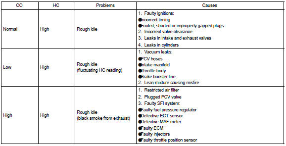
10. INSPECT CO/HC
-
Start the engine.
-
Rev the engine at 2,500 rpm for approximately 180 seconds.
-
Insert CO/HC meter testing probe at least 40 cm (1.3 ft) into the tailpipe during idling.
-
Check CO/HC concentration at idle and/or 2,500 rpm.
HINT: Check regulations and restrictions in your area when performing 2 mode CO/HC concentration testing (engine check at both idle speed and at 2,500 rpm).
If the CO/HC concentration does not comply with regulations, troubleshoot in the order given below.
-
Check A/F operation.
-
See the table below for possible causes, and then inspect and repair.
Engine (2AZ−FE) (From July, 2003)
Timing gear case or timing chain case oil seal (2AZ−FE)(From July, 2003)
Engine rear oil seal (2AZ−FE)(From July, 2003)
Cylinder head assy (2AZ−FE) (From July, 2003)
Cylinder block assy (2AZ−FE)(From July, 2003)
Engine (1MZ−FE/3MZ−FE)
Drive belt (1MZ−FE/3MZ−FE)
Valve clearance (1MZ−FE/3MZ−FE)
Partial engine assy (1MZ−FE/3MZ−FE)
Partial engine assy (2AZ−FE)(From July, 2003)
Partial engine assy (1MZ−FE/3MZ−FE)
Timing belt (1MZ−FE/3MZ−FE)
Camshaft (RH BANK) (1MZ−FE/3MZ−FE)
Camshaft (LH BANK) (1MZ−FE/3MZ−FE)
Cylinder head gasket (1MZ−FE/3MZ−FE)
Cylinder head gasket No.2 (1MZ−FE/3MZ−FE)
Oil pump seal (1MZ−FE/3MZ−FE)
Engine rear oil seal (1MZ−FE/3MZ−FE)
Cylinder head assy (1MZ−FE/3MZ−FE)
Cylinder block assy (1MZ−FE/3MZ−FE)
Partial engine assy (2AZ−FE)(From July, 2003)
Drive belt (2AZ−FE)(From July, 2003)
Valve clearance (2AZ−FE)
Chain (2AZ−FE)(From July, 2003)
Camshaft (2AZ−FE)(From July, 2003)
Cylinder head gasket (2AZ−FE)(From July, 2003)
Toyota Camry XV30 (2002–2006) Service Manual
- Introduction
- Audio & visual system
- Automatic transmission / trans
- Brake
- Clutch
- Communication system
- Cooling
- Cruise control
- Drive shaft / propeller shaft
- Emission control
- Engine control system
- Engine hood/door
- Engine mechanical
- Exhaust
- Exterior/interior trim
- Front suspension
- Fuel
- Heater & air conditioner
- Ignition
- Instrument panel/meter
- Intake
- Lighting
- Lubrication
- Manual transmission/transaxle
- Parking brake
- Power steering
- Rear suspension
- Seat
- Service specifications
- Sliding roof/convertible
- Starting & charging
- Steering column
- Supplemental restraint system
- Theft deterrent & door lock
- Tire & wheel
- Windshield/windowglass/mirror
- Wiper & washer
- Wiring
Categories
