 Toyota Camry XV30 (2002–2006) Service ManualEngine mechanical
Cylinder head assy (2AZ−FE) (From July, 2003)
Cylinder head assy (2AZ−FE) (From July, 2003)
COMPONENTS
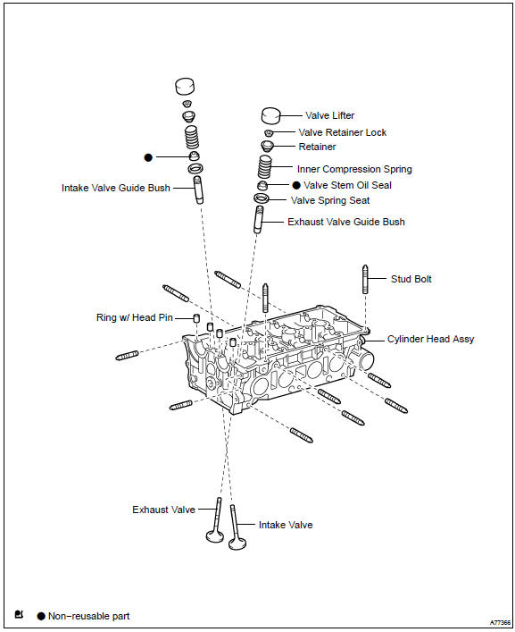
OVERHAUL
1. REMOVE VALVE LIFTER
HINT: Arrange the valve lifters in the correct order.
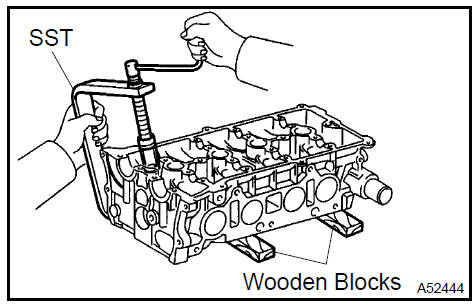
2. REMOVE INTAKE VALVE
-
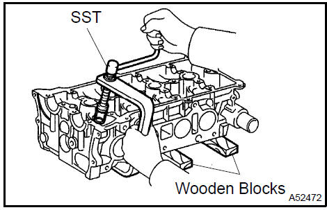
Using SST and wooden blocks, compress and remove the 8 valve spring retainer locks.
SST 09202−70020 (09202−00010)
-
Remove the retainer, valve spring and valve.
HINT: Arrange the removed parts in the correct order.
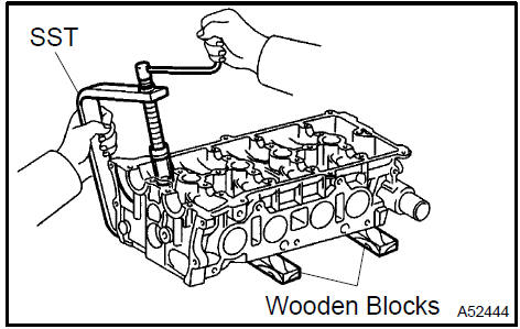
Remove intake valve
3. REMOVE EXHAUST VALVE
-
Using SST and wooden blocks, compress and remove the 8 valve spring retainer locks.
SST 09202−70020 (09202−00010)
-
Remove the retainer, valve spring and valve.
HINT: Arrange the removed parts in the correct order.
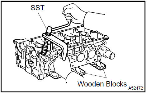
Remove exhaust valve
4. REMOVE VALVE STEM OIL O SEAL OR RING
a. Using needle−nose pliers, remove the oil seals.
Remove valve stem oil o seal or ring
-
REMOVE VALVE SPRING SEAT
-
REMOVE STUD BOLT
-
INSPECT CYLINDER HEAD FOR FLATNESS
a. Using a precision straight edge and a feeler gauge, measure the surface contacting the cylinder block and the manifolds for warpage.
Maximum warpage:
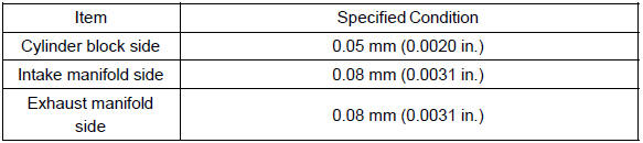
If the warpage is greater than the maximum, replace the cylinder head.
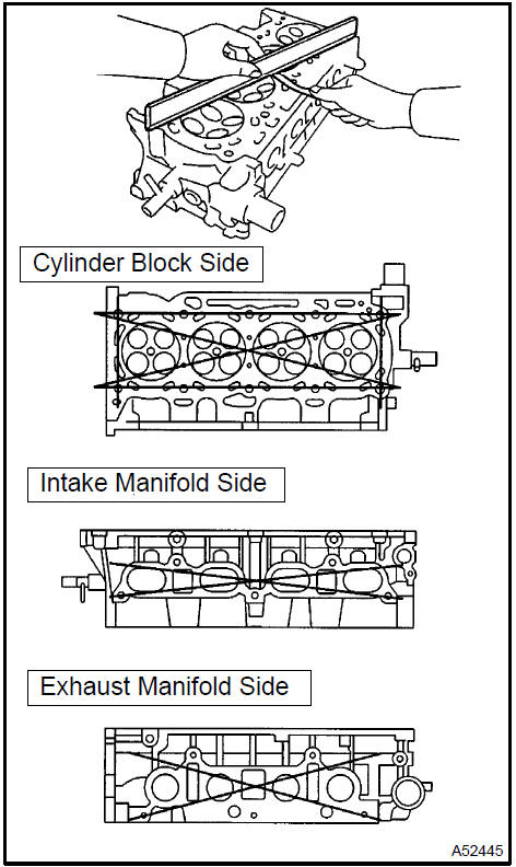
Inspect cylinder head for flatness
8. INSPECT CYLINDER HEAD FOR CRACKS
a. Using a dye penetrate, check the intake ports, exhaust ports and cylinder surface for cracks.
If cracked, replace the cylinder head.
Inspect cylinder head for cracks
9. INSPECT VALVE SEATS
-
Apply a light coat of prussian blue (or white lead) to the valve face.
-
Lightly press the valve face against the valve seat.
-
Check the valve face and valve seat according to the following procedure.
-
If blue appears 360 around the valve face, the valve face is concentric. If not, replace the valve.
-
If blue appears 360 around the valve seat, the guide and valve face are concentric. If not, resurface the valve seat.
-
Check that the valve seat contact is in the middle of the valve face with the width between 1.0 to 1.4 mm (0.039 to 0.055 in.).
Inspect valve seats
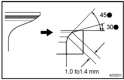
10. REPAIR VALVE SEATS
NOTICE: Keep the lip free from foreign matter.
a. If the seating is too high on the valve face, use 30 and 45 cutters to correct the seat.
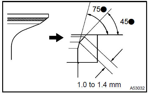
-
If the seating is too low on the valve face, use 75 and 45 cutters to correct the seat.
-
Hand−lap the valve and valve seat with an abrasive compound.
-
Check the valve seating position.
11. INSPECT CAMSHAFT THRUST CLEARANCE
-
Install the camshafts.
-
Using a dial indicator, measure the thrust clearance while moving the camshaft back and forth.
Specified thrust clearance:
If the thrust clearance is greater than the maximum, replace the cylinder head. If the thrust surface is damaged, replace the camshaft.
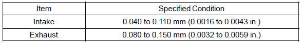
12. INSPECT CAMSHAFT OIL CLEARANCE
-
Clean the bearing caps and camshaft journals.
-
Place the camshafts on the cylinder head.
-
Lay a strip of plastigage across each of the camshaft journal.
d. Install the bearing caps.
Torque:
30 N·m (301 kgf·cm, 22 ft·lbf) for No. 1 bearing cap
30 N·m (301 kgf·cm, 22 ft·lbf) for No. 2 bearing cap
9.0 N·m (92 kgf·cm, 80 in.·lbf) for No. 3 bearing cap
NOTICE: Do not turn the camshaft.
e. Remove the bearing cap, and measure the plastigage at its widest point.
Specified oil clearance:
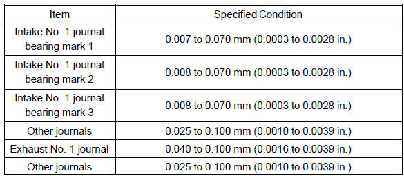
NOTICE: Completely remove the plastigage after the inspection.
If the oil clearance is greater than the maximum, replace the camshaft. If necessary, replace the cylinder head.
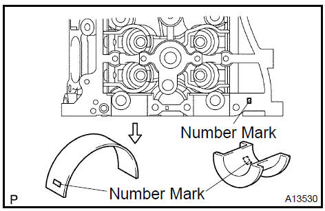
If the oil clearance on the No.1 journal is greater than the maximum, choose a new bearing and install it.
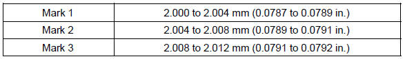
HINT: Cylinder head journal bore diameter
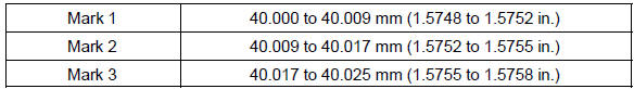
Standard bearing center wall thickness
Camshaft journal diameter: 35.971 to 35.985 mm (1.4162 to 1.4167 in.)
13. INSPECT INNER COMPRESSION SPRING
a. Using a vernier caliper, measure the free length of the valve spring.
Free length: 45.7 mm (1.799 in.)
If the free length is not as specified, replace the valve spring.
b. Using steel squares, measure the deviation of the valve spring.
Maximum deviation: 1.6 mm (0.063 in.)
If the deviation is greater than the maximum, replace the valve spring.
14. INSPECT INTAKE VALVE
a. Using a vernier caliper, measure the valve overall length.
Specified overall length: 101.21 to 101.71 mm (3.9846 to 4.0043 in.)
If the overall length is less than the minimum, replace the valve.
b. Using a micrometer, measure the diameter of the valve stem.
Valve stem diameter: 5.470 to 5.485 mm (0.2154 to 0.2159 in.)
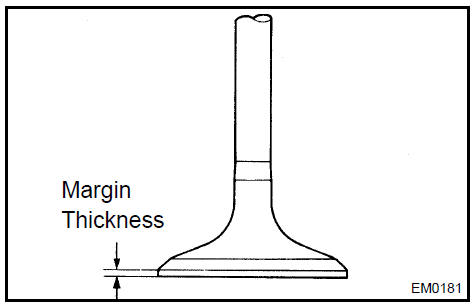
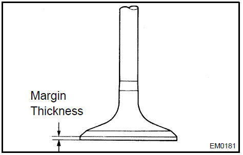
c) Using a vernier caliper, measure the valve head margin thickness.
Specified margin thickness: 0.50 to 1.45 mm (0.0197 to 0.0571 in.)
If the margin thickness is less than the minimum, replace the valve.
15. INSPECT EXHAUST VALVE
a. Using a vernier caliper, measure the valve overall length.
Specified overall length: 100.70 to 101.15 mm (3.9646 to 3.9823 in.)
If the overall length is less than the minimum, replace the valve.
b) Using a micrometer, measure the diameter of the valve stem.
Valve stem diameter: 5.465 to 5.480 mm (0.2152 to 0.2157 in.)
c. Using a vernier caliper, measure the valve head margin thickness.
Specified margin thickness: 0.50 to 1.60 mm (0.0197 to 0.0630 in.)
If the margin thickness is less than the minimum, replace the valve.
16. INSPECT INTAKE VALVE GUIDE BUSH
-
Using a caliper gauge, measure the inside diameter of the guide bush.
Bushing inside diameter: 5.510 to 5.530 mm (0.2169 to 0.2177 in.)
-
Subtract the valve stem diameter measurement from the guide bush inside diameter measurement.
Specified oil clearance: 0.025 to 0.080 mm (0.0010 to 0.0031 in.)
If the clearance is greater than the maximum, replace the valve and guide bush (see steps 18 and 20).
 Inspect intake valve guide bush
17. INSPECT EXHAUST VALVE GUIDE BUSH
-
Using a caliper gauge, measure the inside diameter of the guide bush.
Bushing inside diameter: 5.510 to 5.530 mm (0.2169 to 0.2177 in.)
-
Subtract the valve stem diameter measurement from the guide bushing inside diameter measurement.
Specified oil clearance: 0.030 to 0.100 mm (0.0012 to 0.0039 in.)
If the clearance is greater than the maximum, replace the valve and guide bush (see steps 19 and 21).
Inspect exhaust valve guide bush
18. REMOVE INTAKE VALVE GUIDE BUSH
a. Using SST and a hammer, tap out the guide bush.
SST 09201−10000 (09201−01050), 09950−70010 (09951−07100)
Remove intake valve guide bush
19. REMOVE EXHAUST VALVE GUIDE BUSH
a. Using SST and a hammer, tap out the guide bush.
SST 09201−10000 (09201−01050), 09950−70010 (09951−07100)
20. INSTALL INTAKE VALVE GUIDE BUSH
Using a caliper gauge, measure the bush bore diameter of the cylinder head.
Diameter: 10.285 to 10.306 mm (0.4049 to 0.4057 in.)
Install the STD bush if the diameter is within the specified diameter.
Specified diameter: 10.333 to 10.344 mm (0.4068 to 0.4072 in.)
a) Using SST and a hammer, tap in a new guide bush to the specified protrusion height.
Protrusion height: 9.6 to 10.0 mm (0.3779 to 0.3937 in.)
SST 09201−10000 (09201−01050), 09950−70010 (09951−07100)
b. Using a sharp 5.5 mm reamer, ream the guide bush to obtain the standard specified clearance between the guide bush and valve stem.
Standard oil clearance: 0.025 to 0.060 mm (0.0010 to 0.0024 in.)
21. INSTALL EXHAUST VALVE GUIDE BUSH
-
Using a caliper gauge, measure the bush bore diameter of the cylinder head.
Diameter: 10.285 to 10.306 mm (0.4049 to 0.4057 in.)
-
Install the STD bush if the diameter is within the specified diameter.
Specified diameter: 10.333 to 10.344 mm (0.4068 to 0.4072 in.)
-
Using SST and a hammer, tap in a new guide bush to the specified protrusion height.
Protrusion height: 9.6 to 10.0 mm (0.3779 to 0.3937 in.)
-
Using a sharp 5.5 mm reamer, ream the guide bush to obtain the standard specified clearance between the guide bush and valve stem.
SST 09201−10000 (09201−01050), 09950−70010 (09951−07100)
Standard oil clearance: 0.030 to 0.065 mm (0.0012 to 0.0026 in.)
22. INSPECT VALVE LIFTER
a. Using a micrometer, measure the lifter diameter.
Lifter diameter: 30.966 to 30.976 mm (1.2191 to 1.2195 in.)
-
Using a caliper gauge, measure the lifter bore diameter of the cylinder head.
Lifter bore diameter: 31.009 to 31.025 mm (1.2208 to 1.2215 in.)
-
Subtract the lifter diameter measurement from the lifter bore diameter measurement.
Specified oil clearance: 0.033 to 0.070 mm (0.0013 to 0.0028 in.)
If the oil clearance is greater than the maximum, replace the lifter.
If necessary, replace the cylinder head.
23. INSTALL RING W/HEAD PIN
a. Using a plastic−faced hammer, tap in a new ring pin to the specified protrusion height.
Protrusion height: 3 mm (0.12 in.)
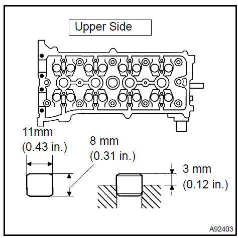
Install ring w/head pin
24. INSTALL STUD BOLT
Torque: 5 N·m (51 kgf·cm, 44 in.·lbf) for bolt A 5 N·m (51 kgf·cm, 44 in.·lbf) for bolt B 10 N·m (97 kgf·cm, 7 ft·lbf) for bolt C 10 N·m (97 kgf·cm, 7 ft·lbf) for bolt D
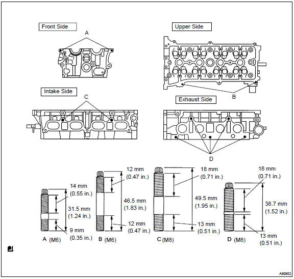 Install stud bolt
-
INSTALL VALVE SPRING SEAT
-
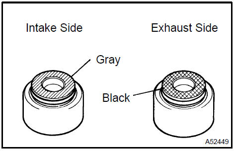
INSTALL VALVE STEM OIL O SEAL OR RING
a. Apply a light coat of engine oil on a new oil seal.
NOTICE: Pay close attention when installing the intake and exhaust oil seals. For example, installing the intake oil seal into the exhaust or installing the exhaust oil seal to the intake can cause installation problems later.
HINT: The intake valve oil seal is gray and the exhaust valve oil seal is black.
b. Using SST, push in the oil seal.
SST 09201−41020
27. INSTALL INTAKE VALVE
-
Install the valve, spring and retainer to the cylinder head.
-
Using SST and wooden blocks, compress the spring and install the 2 retainer locks.
SST 09202−70020 (09202−00010)
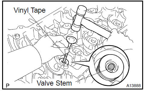
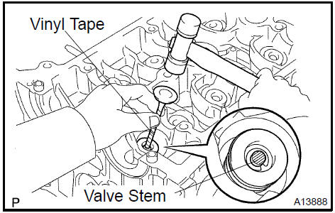
c) Using a plastic−faced hammer and a discarded valve with its tip wrapped in tape, lightly tap the installed valve to ensure that it is securely fit.
NOTICE: Be careful not to damage the valve stem tip.
28. INSTALL EXHAUST VALVE
-
Install the valve, spring and retainer to the cylinder head.
-
Using SST and wooden blocks, compress the spring and install the 2 retainer locks.
SST 09202−70020 (09202−00010)
c. Using a plastic−faced hammer and a discarded valve with its tip wrapped in tape, lightly tap the installed valve to ensure that it is securely fit.
NOTICE: Be careful not to damage the valve stem tip.
29. INSTALL VALVE LIFTER
a. Assemble the valve lifter and the tip of the valve stem with a light coat of engine oil applied.
NOTICE: Install the valve lifters in their original places.
Engine (2AZ−FE) (From July, 2003)
Timing gear case or timing chain case oil seal (2AZ−FE)(From July, 2003)
Engine rear oil seal (2AZ−FE)(From July, 2003)
Cylinder head assy (2AZ−FE) (From July, 2003)
Cylinder block assy (2AZ−FE)(From July, 2003)
Engine (1MZ−FE/3MZ−FE)
Drive belt (1MZ−FE/3MZ−FE)
Valve clearance (1MZ−FE/3MZ−FE)
Partial engine assy (1MZ−FE/3MZ−FE)
Partial engine assy (2AZ−FE)(From July, 2003)
Partial engine assy (1MZ−FE/3MZ−FE)
Timing belt (1MZ−FE/3MZ−FE)
Camshaft (RH BANK) (1MZ−FE/3MZ−FE)
Camshaft (LH BANK) (1MZ−FE/3MZ−FE)
Cylinder head gasket (1MZ−FE/3MZ−FE)
Cylinder head gasket No.2 (1MZ−FE/3MZ−FE)
Oil pump seal (1MZ−FE/3MZ−FE)
Engine rear oil seal (1MZ−FE/3MZ−FE)
Cylinder head assy (1MZ−FE/3MZ−FE)
Cylinder block assy (1MZ−FE/3MZ−FE)
Partial engine assy (2AZ−FE)(From July, 2003)
Drive belt (2AZ−FE)(From July, 2003)
Valve clearance (2AZ−FE)
Chain (2AZ−FE)(From July, 2003)
Camshaft (2AZ−FE)(From July, 2003)
Cylinder head gasket (2AZ−FE)(From July, 2003)
Toyota Camry XV30 (2002–2006) Service Manual
- Introduction
- Audio & visual system
- Automatic transmission / trans
- Brake
- Clutch
- Communication system
- Cooling
- Cruise control
- Drive shaft / propeller shaft
- Emission control
- Engine control system
- Engine hood/door
- Engine mechanical
- Exhaust
- Exterior/interior trim
- Front suspension
- Fuel
- Heater & air conditioner
- Ignition
- Instrument panel/meter
- Intake
- Lighting
- Lubrication
- Manual transmission/transaxle
- Parking brake
- Power steering
- Rear suspension
- Seat
- Service specifications
- Sliding roof/convertible
- Starting & charging
- Steering column
- Supplemental restraint system
- Theft deterrent & door lock
- Tire & wheel
- Windshield/windowglass/mirror
- Wiper & washer
- Wiring
Categories
