 Toyota Camry XV30 (2002–2006) Service ManualEngine mechanical
Cylinder head gasket (2AZ−FE)(From July, 2003)
Cylinder head gasket (2AZ−FE)(From July, 2003)
REPLACEMENT
- WORK FOR PREVENTING GASOLINE FROM SPILLING OUT
- REMOVE FRONT SUSPENSION UPPER BRACE CENTER (W/ FRONT SUSPENSION BRACE UPPER CENTER)
- DRAIN COOLANT
- DISCONNECT RADIATOR HOSE OUTLET
- DISCONNECT UNION TO CONNECTOR TUBE HOSE
- SCONNECT HEATER INLET WATER HOSE
- DISCONNECT FUEL TUBE SUB−ASSY
- REMOVE INTAKE MANIFOLD
- Disconnect the 2 Ωater by−pass hoses of the throttle body.
- Remove the 5 bolts, 2 nuts, intake manifold and gasket.
 Remove intake manifold
- REMOVE INTAKE MANIFOLD RUNNER VALVE ASSY
- DISCONNECT ENGINE WIRE
- REMOVE INTAKE MANIFOLD INSULATOR No.1
- REMOVE EXHAUST MANIFOLD HEAT INSULATOR No.1
- REMOVE EXHAUST MANIFOLD CONVERTER SUB−ASSY
a. Remove the 3 bolts, 2 nuts, No. 1 and No. 2 exhaust manifold stays.
b. Remove the 5 nuts, exhaust manifold and gasket.
- REMOVE CHAIN SUB−ASSY
- REMOVE No.2 CAMSHAFT
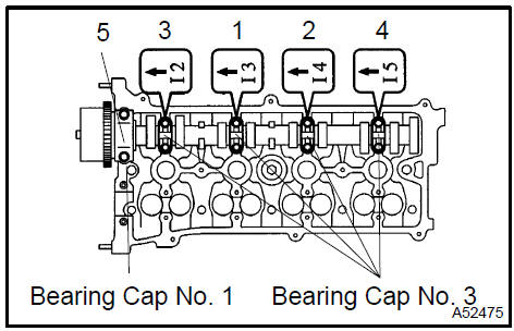
- Uniformly loosen and remove the No. 2 camshaft’s 10
bearing cap bolts in the sequence shown in the illustration.
Then remove the 5 bearings.
- Remove the camshaft.
 Remove No.2 Camshaft
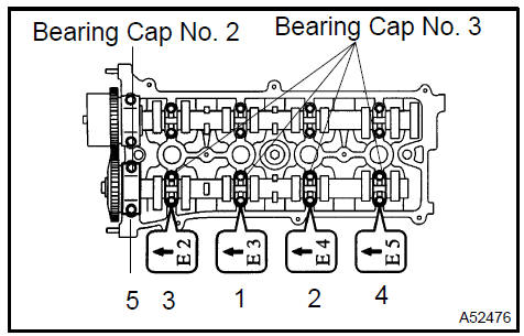
16. REMOVE CAMSHAFT
- Uniformly loosen and remove the No. 2 camshaft’s 10
bearing cap bolts in the sequence shown in the illustration.
Then remove the 5 bearings.
- Remove the camshaft.
 Remove camshaft
- REMOVE CAMSHAFT BEARING No.2
- REMOVE CAMSHAFT TIMING OIL CONTROL VALVE ASSY
- REMOVE CYLINDER HEAD SUB−ASSY
a. Using a 10 mm bi−hexagon wrench, uniformly loosen the 10 bolts in the sequence shown in the illustration. Remove the 10 cylinder head bolts and plate washers.
NOTICE:
- Be careful not to drop washers into the cylinder head.
- Head warpage or cracking could result from removing bolts in an incorrect order.
 Remove cylinder head sub-assy
- REMOVE CYLINDER HEAD GASKET
- INSPECT CYLINDER HEAD SET BOLT
a. Using a vernier caliper, measure the length of the head bolts from the seat to the end.
Specified bolt length:
161.3 to 164.2 mm (6.350 to 6.465 in.)
If the length is greater than the maximum, replace the bolt.
 Inspect cylinder head set bolt
22. INSTALL CYLINDER HEAD GASKET
a. Place a new gasket on the cylinder block surface with the Lot No. stamp upward.
NOTICE:
- Remove any oil from contact surface.
- Be careful of the installation direction.
- To avoid damage to the gasket, place the cylinder head on the gasket carefully.
23. INSTALL CYLINDER HEAD SUB−ASSY
HINT: The cylinder head bolts are tightened in 2 progressive steps.
- Apply a light coat of engine oil on the threads and under the heads of the cylinder head bolts.
- Install the bolts and plate washers to the cylinder head.
NOTICE: Do not drop the washers into the cylinder head.
c. Using a 10 mm bi−hexagon wrench, uniformly tighten the 10 bolts in the sequence shown in the illustration.
Torque: 79 N·m (806 kgf·cm, 58 ft·lbf)
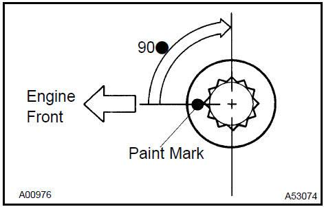
- Mark the front side of the cylinder head bolt with paint.
- Retighten the cylinder head bolts by 90 in the sequence shown in the illustration.
- Check that the painted mark is now at a 90 angle to the front.
- INSTALL CAMSHAFT TIMING OIL CONTROL VALVE ASSY Torque: 9.0 N·m (92 kgf·cm, 80 in.·lbf)
- INSTALL CAMSHAFT BEARING No.2
- INSTALL CAMSHAFT
a. Examine the front marks and numbers of the 5 bearing caps and install them. Then install the 10 bearing cap bolts. Uniformly tighten the bolts in the sequence shown in the illustration.
Torque: 30 N·m (301 kgf·cm, 22 ft·lbf) for bearing cap No. 1 9.0 N·m (92 kgf·cm, 80 in.·lbf) for bearing cap No. 3
 Install camshaft
27. INSTALL No.2 CAMSHAFT
a. Examine the front marks and numbers of the 5 bearing caps and install them. Then install the 10 bearing cap bolts. Uniformly tighten the bolts in the sequence shown in the illustration.
Torque: 30 N·m (301 kgf·cm, 22 ft·lbf) for bearing cap No.2 9.0 N·m (92 kgf·cm, 80 in.·lbf) for bearing cap No.3
 Install No.2 Camshaft
- INSTALL CHAIN SUB−ASSY
- INSTALL EXHAUST MANIFOLD CONVERTER SUB−ASSY
a. Install a new gasket and the exhaust manifold with the 5 nuts.
Torque: 37 N·m (378 kgf·cm, 27 ft·lbf)
b. Install the No. 1 and No. 2 exhaust manifold stays with the 3 bolts and 2 nuts.
Torque: 44 N·m (449 kgf·cm, 32 ft·lbf)
- INSTALL EXHAUST MANIFOLD HEAT INSULATOR No.1 Torque: 12 N·m (122 kgf·cm, 9 ft·lbf)
- INSTALL INTAKE MANIFOLD RUNNER VALVE ASSY
- INSTALL INTAKE MANIFOLD
a Install a new gasket and the intake manifold with the 5 bolts and 2 nuts.
Torque: 30 N·m (306 kgf·cm, 22 ft·lbf)
 Install intake manifold
- CONNECT FUEL TUBE SUB−ASSY
- ADD ENGINE OIL
- ADD ENGINE COOLANT
- CHECK FOR ENGINE OIL LEAKS
- CHECK FOR ENGINE COOLANT LEAKS
- INSPECT FOR FUEL LEAKS
- INSPECT CHECK IDLE SPEED AND IGNITION TIMING
- INSPECT CO/HC
Engine (2AZ−FE) (From July, 2003)
Timing gear case or timing chain case oil seal (2AZ−FE)(From July, 2003)
Engine rear oil seal (2AZ−FE)(From July, 2003)
Cylinder head assy (2AZ−FE) (From July, 2003)
Cylinder block assy (2AZ−FE)(From July, 2003)
Engine (1MZ−FE/3MZ−FE)
Drive belt (1MZ−FE/3MZ−FE)
Valve clearance (1MZ−FE/3MZ−FE)
Partial engine assy (1MZ−FE/3MZ−FE)
Partial engine assy (2AZ−FE)(From July, 2003)
Partial engine assy (1MZ−FE/3MZ−FE)
Timing belt (1MZ−FE/3MZ−FE)
Camshaft (RH BANK) (1MZ−FE/3MZ−FE)
Camshaft (LH BANK) (1MZ−FE/3MZ−FE)
Cylinder head gasket (1MZ−FE/3MZ−FE)
Cylinder head gasket No.2 (1MZ−FE/3MZ−FE)
Oil pump seal (1MZ−FE/3MZ−FE)
Engine rear oil seal (1MZ−FE/3MZ−FE)
Cylinder head assy (1MZ−FE/3MZ−FE)
Cylinder block assy (1MZ−FE/3MZ−FE)
Partial engine assy (2AZ−FE)(From July, 2003)
Drive belt (2AZ−FE)(From July, 2003)
Valve clearance (2AZ−FE)
Chain (2AZ−FE)(From July, 2003)
Camshaft (2AZ−FE)(From July, 2003)
Cylinder head gasket (2AZ−FE)(From July, 2003)
Toyota Camry XV30 (2002–2006) Service Manual
- Introduction
- Audio & visual system
- Automatic transmission / trans
- Brake
- Clutch
- Communication system
- Cooling
- Cruise control
- Drive shaft / propeller shaft
- Emission control
- Engine control system
- Engine hood/door
- Engine mechanical
- Exhaust
- Exterior/interior trim
- Front suspension
- Fuel
- Heater & air conditioner
- Ignition
- Instrument panel/meter
- Intake
- Lighting
- Lubrication
- Manual transmission/transaxle
- Parking brake
- Power steering
- Rear suspension
- Seat
- Service specifications
- Sliding roof/convertible
- Starting & charging
- Steering column
- Supplemental restraint system
- Theft deterrent & door lock
- Tire & wheel
- Windshield/windowglass/mirror
- Wiper & washer
- Wiring
Categories
