 Toyota Camry XV30 (2002–2006) Service ManualEngine mechanical
Camshaft (LH BANK) (1MZ−FE/3MZ−FE)
Camshaft (LH BANK) (1MZ−FE/3MZ−FE)
REPLACEMENT
-
DRAIN ENGINE COOLANT
-
REMOVE V−BANK COVER SUB−ASSY
-
REMOVE RADIATOR HOSE INLET
-
REMOVE SPARK PLUG
-
REMOVE CYLINDER HEAD COVER SUB−ASSY LH
-
REMOVE FRONT WHEEL RH
-
REMOVE FRONT FENDER APRON SEAL RH
-
REMOVE V (COOLER COMPRESSOR TO CRANKSHAFT PULLEY) BELT No.1
-
REMOVE VANE PUMP V BELT
-
REMOVE ENGINE MOVING CONTROL ROD
-
REMOVE ENGINE MOUNTING STAY No.2 RH
-
REMOVE GENERATOR BRACKET No.2
-
REMOVE CRANKSHAFT PULLEY
-
REMOVE TIMING BELT No.1 COVER
-
REMOVE TIMING BELT No.2 COVER
-
REMOVE ENGINE MOUNTING BRACKET RH
-
REMOVE TIMING BELT GUIDE No.2
-
REMOVE TIMING BELT
-
REMOVE TIMING BELT IDLER SUB−ASSY No.2
-
REMOVE CAMSHAFT TIMING PULLEY
-
REMOVE TIMING BELT No.3 COVER
-
REMOVE No.3 CAMSHAFT SUB−ASSY
NOTICE: Since the thrust clearance of the camshaft is small, the camshaft must be kept level while it is being removed. If the camshaft is not kept level, damage to the cylinder head or to the camshaft may result. To avoid this, the following steps must be carried out.
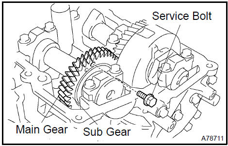
a. Align the camshaft drive and driven gear’s timing marks (1 dot mark each) by turning the camshaft with a wrench.
b. Secure the exhaust camshaft sub gear to the main gear with a service bolt.
Recommended service bolt:
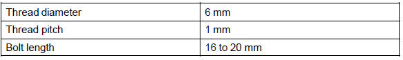
Torque: 5.4 N·m (55 kgf·cm, 48 in.·lbf)
HINT: When removing the camshaft, make certain that the torsional spring force of the sub gear has been eliminated by installation of the service bolt.
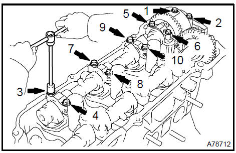
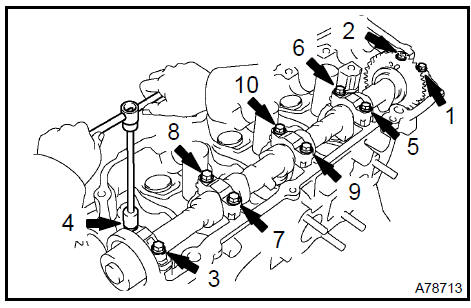
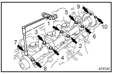
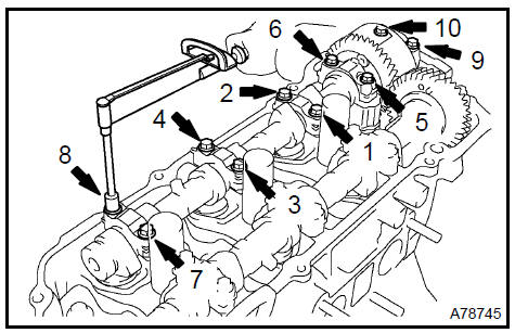
c. Uniformly loosen and remove the 10 bearing cap bolts in the sequence shown in the illustration. Remove the 5 bearing caps and the No. 3 camshaft.
NOTICE:
-
Do not pry out the camshaft.
-
Be careful not to damage the portion of the cylinder head receiving the shaft thrust.
23. REMOVE No.4 CAMSHAFT SUB−ASSY
a. Uniformly loosen and remove the 10 bearing cap bolts in the sequence shown in the illustration. Remove the 5 bearing caps and the No. 4 camshaft.
NOTICE:
-
Do not pry out the camshaft.
-
Be careful not to damage the portion of the cylinder head receiving the shaft thrust.
b. Remove the oil seal from the No. 4 camshaft.
-
REMOVE CAMSHAFT TIMING GEAR ASSY
-
REMOVE CAMSHAFT SUB GEAR No.3
-
INSTALL CAMSHAFT SUB GEAR No.3
-
INSTALL CAMSHAFT TIMING GEAR ASSY
-
INSTALL No.4 CAMSHAFT SUB−ASSY
NOTICE: Since the thrust clearance of the camshaft is small, the camshaft must be kept level while it is being installed. If the camshaft is not kept level, damage to the cylinder head or to the camshaft may result. To avoid this, the following steps must be carried out.
-
Apply new engine oil to the thrust portion and journal of the camshaft.
-
Place the No. 4 camshaft at a 90 angle of the timing mark (1 dot marks) on the cylinder head.
-
Apply MP grease to a new oil seal lip.
d. Install the oil seal to the camshaft.
NOTICE:
-
Do not turn over the oil seal lip.
-
Insert the oil seal until it stops.
-
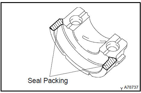
Remove any old packing material from the contact surface.
-
Apply seal packing to the No. 1 bearing cap as shown in the illustration.
Seal packing: Part No. 08826−00080 or equivalent
NOTICE:
-
Install the No. 1 bearing cap within 5 minutes after applying seal packing.
-
Do not expose the seal to engine oil for at least 2 hours after installing.
-
Install the 5 bearing caps in their proper locations.
-
Apply a light coat of engine oil on the threads of the bearing cap bolts.
i. Uniformly install and tighten the 10 bearing cap bolts in the sequence shown in the illustration.
Torque: 16 N·m (163 kgf·cm, 12 ft·lbf)
29. INSTALL No.3 CAMSHAFT SUB−ASSY
NOTICE: Since the thrust clearance of the camshaft is small, the camshaft must be kept level while it is being installed. If the camshaft is not kept level, damage to the cylinder head or to the camshaft may result. To avoid this, the following steps must be carried out.
-
Apply new engine oil to the thrust portion and journal of the camshaft.
-
Align the camshaft drive and driven gear’s timing mark (1 dot mark each).
-
Place the camshaft on the cylinder head.
-
Install the 5 bearing caps in their proper locations.
-
Apply a light coat of engine oil on the threads of the bearing cap bolts.
-
Uniformly install and tighten the 10 bearing cap bolts in the sequence shown in the illustration.
Torque: 16 N·m (163 kgf·cm, 12 ft·lbf)
-
Remove the service bolt.
-
INSTALL TIMING BELT No.3 COVER
-
INSTALL CAMSHAFT TIMING PULLEY
-
INSTALL TIMING BELT IDLER SUB−ASSY No.2 Torque: 43 N·m (438 kgf·cm, 32 ft·lbf)
-
INSPECT TIMING BELT
-
INSTALL TIMING BELT
-
INSTALL TIMING BELT TENSIONER ASSY
-
INSTALL TIMING BELT GUIDE No.2
-
INSTALL ENGINE MOUNTING BRACKET RH Torque: 28 N·m (286 kgf·cm, 21 ft·lbf)
-
INSTALL TIMING BELT No.2 COVER
-
INSTALL TIMING BELT No.1 COVER
-
INSTALL CRANKSHAFT PULLEY
-
INSTALL GENERATOR BRACKET No.2 Torque: 28 N·m (286 kgf·cm, 21 ft·lbf)
-
INSTALL ENGINE MOUNTING STAY No.2 RH
-
INSTALL ENGINE MOVING CONTROL ROD
-
INSPECT VALVE CLEARANCE
-
ADJUST VALVE CLEARANCE
-
INSTALL VANE PUMP V BELT
-
INSTALL V (COOLER COMPRESSOR TO CRANKSHAFT PULLEY) BELT No.1
-
INSPECT DRIVE BELT TENSION
-
INSTALL CYLINDER HEAD COVER SUB−ASSY LH
-
INSTALL SPARK PLUG Torque: 8.0 N·m (82 kgf·cm, 71 in.·lbf)
-
INSTALL V−BANK COVER SUB−ASSY
-
INSTALL FRONT WHEEL RH Torque: 103 N·m (1,050 kgf·cm, 76 ft·lbf)
-
ADD ENGINE COOLANT
-
CHECK FOR ENGINE COOLANT LEAKS
Engine (2AZ−FE) (From July, 2003)
Timing gear case or timing chain case oil seal (2AZ−FE)(From July, 2003)
Engine rear oil seal (2AZ−FE)(From July, 2003)
Cylinder head assy (2AZ−FE) (From July, 2003)
Cylinder block assy (2AZ−FE)(From July, 2003)
Engine (1MZ−FE/3MZ−FE)
Drive belt (1MZ−FE/3MZ−FE)
Valve clearance (1MZ−FE/3MZ−FE)
Partial engine assy (1MZ−FE/3MZ−FE)
Partial engine assy (2AZ−FE)(From July, 2003)
Partial engine assy (1MZ−FE/3MZ−FE)
Timing belt (1MZ−FE/3MZ−FE)
Camshaft (RH BANK) (1MZ−FE/3MZ−FE)
Camshaft (LH BANK) (1MZ−FE/3MZ−FE)
Cylinder head gasket (1MZ−FE/3MZ−FE)
Cylinder head gasket No.2 (1MZ−FE/3MZ−FE)
Oil pump seal (1MZ−FE/3MZ−FE)
Engine rear oil seal (1MZ−FE/3MZ−FE)
Cylinder head assy (1MZ−FE/3MZ−FE)
Cylinder block assy (1MZ−FE/3MZ−FE)
Partial engine assy (2AZ−FE)(From July, 2003)
Drive belt (2AZ−FE)(From July, 2003)
Valve clearance (2AZ−FE)
Chain (2AZ−FE)(From July, 2003)
Camshaft (2AZ−FE)(From July, 2003)
Cylinder head gasket (2AZ−FE)(From July, 2003)
Toyota Camry XV30 (2002–2006) Service Manual
- Introduction
- Audio & visual system
- Automatic transmission / trans
- Brake
- Clutch
- Communication system
- Cooling
- Cruise control
- Drive shaft / propeller shaft
- Emission control
- Engine control system
- Engine hood/door
- Engine mechanical
- Exhaust
- Exterior/interior trim
- Front suspension
- Fuel
- Heater & air conditioner
- Ignition
- Instrument panel/meter
- Intake
- Lighting
- Lubrication
- Manual transmission/transaxle
- Parking brake
- Power steering
- Rear suspension
- Seat
- Service specifications
- Sliding roof/convertible
- Starting & charging
- Steering column
- Supplemental restraint system
- Theft deterrent & door lock
- Tire & wheel
- Windshield/windowglass/mirror
- Wiper & washer
- Wiring
Categories
